Rail weld failures remain one of the most critical risks in railway infrastructure, often leading to costly disruptions and safety concerns. In this context, PAUT vs TOFD becomes a crucial comparison for engineers seeking reliable inspection methods. The discussion around PAUT vs TOFD continues to grow as industries demand higher accuracy and efficiency in weld evaluation.
Rail systems operate under continuous mechanical stress. Each passing train introduces cyclic loading, which gradually weakens weld joints. Even a small internal defect can evolve into a critical failure if not detected early. This makes inspection not just a routine task but a vital safety measure.
Modern non-destructive testing (NDT) methods have transformed how rail welds are evaluated. Advanced ultrasonic techniques now offer deeper insights into weld integrity. However, selecting the right method requires understanding both performance and limitations.
Understanding Rail Weld Inspection and Why It Matters
Rail welds act as the backbone of continuous track systems. Any failure in these joints can compromise the entire rail line. Studies in railway maintenance reports indicate that a large portion of rail defects originates from weld zones.
Inspection standards like EN 16729 and AREMA guidelines emphasize early detection. These standards aim to minimize derailments and ensure long-term reliability. However, traditional inspection techniques often fall short when dealing with complex weld geometries.
Conventional ultrasonic testing relies on single-angle beams. This limits its ability to detect certain defect orientations. Radiographic testing provides internal imaging but introduces safety risks due to radiation exposure. It also requires controlled environments, making it less practical for field inspections.
Rail operators today look for inspection methods that provide:
- Accurate defect detection
- Fast scanning speeds
- Reliable flaw sizing
- Minimal operational disruption
Advanced ultrasonic methods like phased array and diffraction-based testing address these needs. They offer improved imaging, better coverage, and higher reliability.
However, the real question lies in understanding how these technologies actually function. Without that clarity, selecting the right method becomes guesswork rather than strategy.
Now that the importance of inspection is clear, what truly separates these advanced methods at a technical level? The answer unfolds in the next section.
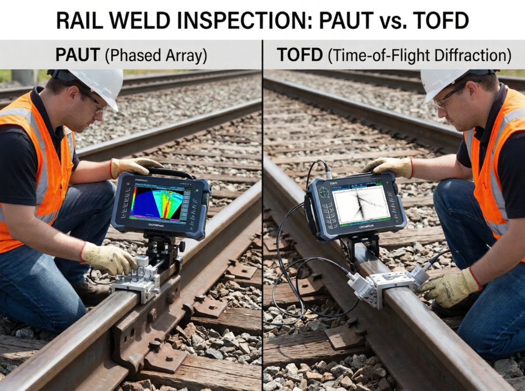
What Is the Difference Between TOFD and Phased Array?
TOFD and phased array represent two advanced ultrasonic testing approaches. Both aim to detect internal defects, but they rely on different physical principles.
How TOFD Works
Time of Flight Diffraction (TOFD) operates by analyzing diffracted ultrasonic waves. Unlike traditional methods that depend on reflected signals, TOFD focuses on signals that originate from the edges of defects.
A TOFD setup typically includes two probes placed on opposite sides of the weld. One probe transmits ultrasonic waves, while the other receives them. When these waves encounter a flaw, they diffract from its tips.
The system records the time it takes for these signals to travel. Using this data, it calculates the depth and size of the defect with high precision.
TOFD offers excellent sizing accuracy because it measures the exact position of defect tips. This makes it highly reliable for assessing flaw severity in thicker materials.
However, TOFD may struggle with detecting very small defects. It also has limitations near the surface, where signal interpretation becomes more complex.
How PAUT Works
Phased Array Ultrasonic Testing (PAUT) uses multiple transducer elements arranged in a single probe. These elements can be controlled electronically to steer ultrasonic beams at different angles.
This capability allows PAUT to scan a wide area without physically moving the probe. It also enables real-time imaging of the weld structure.
PAUT systems generate detailed cross-sectional images. These images help inspectors identify defects more clearly and make informed decisions.
Step-by-Step Working Principle of PAUT
- The probe activates multiple ultrasonic elements in a controlled sequence
- Electronic delays steer the beam at different angles
- Ultrasonic waves penetrate the weld from multiple directions
- Reflected signals return to the probe array
- Software processes the signals into a visual representation
This process allows PAUT to detect a wide range of defects, including cracks, lack of fusion, and inclusions.
PAUT’s flexibility makes it suitable for complex weld geometries. It can adapt to different inspection scenarios without requiring major setup changes.
Both methods offer advanced capabilities, but their differences become clearer when performance is evaluated under real conditions.
With both technologies explained, how do they truly compare when applied to rail weld inspection? The next section reveals the answer.
PAUT vs TOFD: Head-to-Head Performance Comparison
The comparison of PAUT vs TOFD becomes more meaningful when performance factors are analyzed side by side. Each method brings unique strengths, but also specific limitations.
Detection capability plays a key role in rail inspection. PAUT offers high sensitivity due to its multi-angle scanning. It can detect small and complex defects that may go unnoticed with other methods.
TOFD, while reliable, focuses more on defect sizing than detection. It performs best when flaws are already present and need accurate measurement.
Inspection speed also varies between the two. PAUT covers larger areas quickly due to electronic beam steering. This reduces inspection time and improves efficiency.
TOFD requires precise probe positioning. This can slow down the inspection process, especially in field conditions.
Another important factor is adaptability. Rail welds often vary in geometry and thickness. PAUT handles these variations effectively due to its flexible scanning capabilities.
TOFD performs best in consistent, thicker sections. Its effectiveness may decrease when dealing with thinner materials or complex weld shapes.
PAUT vs TOFD Comparison
| Parameter | PAUT | TOFD |
| Detection Capability | High sensitivity, detects small defects | Moderate sensitivity |
| Inspection Speed | Fast due to wide coverage | Slower due to setup requirements |
| Thickness Range | Suitable for thin and thick materials | Best for medium to thick materials |
| Defect Sizing | Good, image-based interpretation | Excellent depth accuracy |
| Portability | Highly portable systems | Moderate portability |
| Standards Compliance | Widely accepted across industries | Often used alongside other methods |
| Best Use Case | Complex weld inspection | Precise defect sizing |
This comparison highlights how each method serves a different purpose. PAUT provides flexibility, speed, and high detection capability. TOFD delivers precise measurements and reliable sizing.
Rail inspection often requires a balance between detection and measurement. In many cases, inspectors combine both methods to achieve comprehensive results.
The choice between these techniques depends on several factors, including weld geometry, inspection speed, and required accuracy.
What Is the Minimum Thickness for TOFD?
The minimum thickness for TOFD typically starts around 6 mm, but optimal performance is achieved in thicker materials. This limitation directly affects how effectively TOFD can be applied in rail weld inspection.
TOFD relies on diffracted signals from defect tips. In thinner materials, these signals can overlap with lateral waves, making interpretation difficult. This reduces detection reliability, especially near the surface.
Rail welds often include sections where the thickness varies. In such cases, TOFD may not deliver consistent results across the entire weld. This creates challenges for inspectors who require uniform accuracy.
Key Thickness-Related Limitations of TOFD
- Difficulty in detecting near-surface defects due to signal interference
- Reduced accuracy in thin materials below the recommended thickness
- Overlapping signals that complicate interpretation
- Limited effectiveness in complex weld geometries
- Dependence on precise probe alignment
These limitations highlight why TOFD alone may not always meet the demands of rail inspection. While it excels in sizing, its constraints in thinner sections cannot be ignored.
This is where the PAUT vs TOFD discussion becomes even more relevant. PAUT adapts more effectively to varying thicknesses, making it a preferred choice in many rail applications.
However, thickness is only one part of the equation. A deeper understanding of advantages and limitations reveals a clearer picture of how each method performs overall.
If thickness defines capability, then what about overall strengths and weaknesses? The next section breaks this down in detail.
Advantages and Limitations of PAUT vs TOFD
A balanced evaluation of PAUT vs TOFD requires examining both strengths and weaknesses. Each method offers unique benefits, but neither provides a complete solution on its own.
Advantages of PAUT
PAUT stands out for its flexibility and advanced imaging capabilities. It allows inspectors to detect and analyze defects with high precision.
- Provides real-time imaging of weld structures
- Covers large areas quickly with minimal probe movement
- Detects small and complex defects effectively
- Adapts to different weld geometries and thicknesses
- Reduces inspection time and operational downtime
These advantages make PAUT highly suitable for modern rail inspection requirements. Its ability to visualize defects enhances decision-making and improves reliability.
Advantages of TOFD
TOFD offers exceptional accuracy in defect sizing. It provides precise measurements that help assess the severity of flaws.
- Delivers highly accurate depth measurements
- Provides consistent results in thicker materials
- Offers repeatable and reliable data
- Works well for monitoring defect growth over time
- Requires less interpretation compared to imaging methods
TOFD’s strength lies in its ability to quantify defects. This makes it valuable for assessing structural integrity and planning maintenance.
Where Each Method Falls Short
Despite their strengths, both methods have limitations. PAUT requires skilled operators and advanced equipment. Interpretation of images can vary depending on expertise.
TOFD struggles with detecting small and surface-breaking defects. It also faces challenges in thin materials and complex geometries.
In many real-world scenarios, relying on a single method may not provide complete results. This is why industries often combine both techniques for comprehensive inspection.
The PAUT vs TOFD comparison shows that each method complements the other rather than replacing it.
As strengths and limitations become clear, another question naturally arises: how does PAUT compare with other widely used NDT methods like radiographic testing?
The answer provides even deeper insight into choosing the right inspection approach.
What Is the Difference Between RT and PAUT?
Radiographic Testing (RT) and PAUT both aim to detect internal defects, but they operate on entirely different principles.
RT uses X-rays or gamma rays to create images of the internal structure. It provides a permanent record of the weld condition. However, it involves radiation hazards and requires strict safety measures.
PAUT, on the other hand, uses ultrasonic waves. It does not involve radiation, making it safer for field applications. It also provides real-time results, which improves inspection efficiency.
Another key difference lies in adaptability. RT requires access to both sides of the weld and controlled conditions. PAUT can be performed from one side and adapts to various environments.
When comparing RT with PAUT in the context of PAUT vs TOFD, PAUT emerges as a more versatile and safer option for rail inspections.
RT still holds value in certain applications, especially where permanent records are required. However, its limitations in speed and safety make it less practical for large-scale rail networks.
Choosing the Right Method for Rail Weld Inspection
Selecting the right inspection method depends on multiple factors. Rail operators must consider weld geometry, material thickness, inspection speed, and safety requirements.
The PAUT vs TOFD debate often leads to a combined approach. Using both methods together provides a more comprehensive evaluation.
PAUT ensures high detection capability and coverage. TOFD delivers precise sizing of detected defects. Together, they create a balanced inspection strategy.
Industry standards such as EN 15085, AREMA, and AWS D1.1 support the use of advanced ultrasonic methods. These standards emphasize accuracy, reliability, and safety in weld inspection.
Experts in the field often recommend hybrid inspection techniques. As one industry specialist noted, “Combining phased array with diffraction methods provides both detection confidence and measurement accuracy.”
This approach reduces the risk of missed defects and improves maintenance planning.
Final Thoughts
Rail weld inspection continues to evolve as safety standards become more demanding. In this landscape, the comparison of PAUT vs TOFD plays a crucial role in guiding inspection strategies. Each method brings distinct advantages that address specific challenges in rail weld evaluation.
PAUT stands out for its flexibility, speed, and ability to detect complex defects across varying weld geometries. It provides real-time imaging, which helps inspectors make faster and more informed decisions. On the other hand, TOFD delivers exceptional accuracy in defect sizing, making it highly reliable for assessing flaw severity in thicker sections.
The PAUT vs TOFD discussion clearly shows that no single method can fully address all inspection needs. Rail environments often require both high detection sensitivity and precise measurement. This is why many industry professionals adopt a combined approach to achieve comprehensive results.
Ultimately, the choice depends on inspection requirements, material thickness, and operational constraints. A well-informed decision ensures better safety, reduced maintenance costs, and improved rail performance. Understanding PAUT vs TOFD allows inspection teams to select the most effective strategy and maintain the integrity of critical rail infrastructure.
Key Takeaways
- Rail weld inspection plays a critical role in preventing failures and ensuring long-term infrastructure safety.
- The comparison of PAUT vs TOFD helps professionals select the most suitable inspection method.
- PAUT provides high detection capability through multi-angle scanning and advanced real-time imaging features.
- TOFD excels in accurate defect sizing, especially in thicker rail weld sections.
- Material thickness significantly influences the effectiveness of TOFD in weld inspection applications.
- PAUT adapts better to complex weld geometries and varying rail section conditions.
- Combining PAUT and TOFD often delivers more reliable and comprehensive inspection results.
- Industry standards emphasize the use of advanced ultrasonic methods for improved safety compliance.
- Operator skill and proper equipment selection greatly impact the accuracy of inspection outcomes.
- Understanding PAUT vs TOFD enables better decision-making for efficient and cost-effective rail maintenance strategies.
FAQs
What is TOFD in NDT?
TOFD (Time of Flight Diffraction) is an ultrasonic testing method that detects flaws using diffracted sound waves. It provides highly accurate measurements of defect depth and size. It is widely used in weld inspection, especially for thicker materials.
What are the two types of phased arrays?
The two main types of phased arrays are linear phased arrays and sectorial (or angular) phased arrays. Linear arrays scan in a straight line, while sectorial arrays sweep through multiple angles. Both improve defect detection compared to conventional ultrasonic testing.
What is the most extensively used weld inspection method?
Ultrasonic testing is one of the most widely used weld inspection methods. Among advanced techniques, PAUT is highly preferred due to its accuracy and real-time imaging. It offers better coverage and faster inspection compared to traditional methods.
What are the advantages of phased array?
Phased array offers high flexibility, faster inspection, and detailed imaging of welds. It can scan multiple angles without moving the probe. This improves defect detection and reduces inspection time.
What are the NDT methods for rail defect detection?
Common NDT methods for rail inspection include PAUT, TOFD, conventional ultrasonic testing, and radiographic testing. Each method serves a specific purpose in detecting and sizing defects. Advanced methods like PAUT and TOFD are widely used for improved accuracy.