
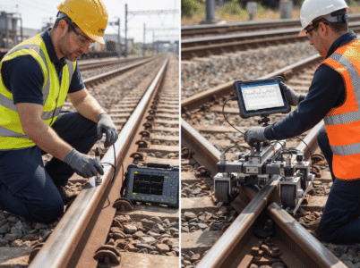
Rail defects don’t announce themselves. A hairline crack hidden beneath the surface. A subsurface break developing silently over months. These threats demand detection methods that actually work which is precisely why the choice between ultrasonic testing vs magnetic flux leakage matters so much to rail operators worldwide. The technology selected determines what gets caught and what slips through, making the comparison between ultrasonic testing vs magnetic flux leakage far more than a technical detail.
Every day, trains carry millions of passengers and countless tonnes of cargo across aging infrastructure. The stakes for getting inspection right couldn’t be higher. Rail operators face a seemingly simple question that turns out to be remarkably complex: which inspection technology delivers superior defect detection? The answer lies in understanding how ultrasonic testing vs magnetic flux leakage each approach the challenge differently because they do, fundamentally.
This article compares both methods with the specifics rail professionals need. Not marketing claims. Not oversimplified summaries. Just the actual capabilities, limitations, costs, and practical realities of ultrasonic testing vs magnetic flux leakage as they exist in 2026.
Why Rail Inspection Standards Matter Today
The consequences aren’t abstract. A single undetected transverse crack can propagate during high-speed operation, leading to derailment. A missed lamination defect becomes a break under heavy axle loads. These aren’t theoretical risks they happen.
And this reality is why rail operators cannot simply pick whichever inspection method seems convenient. The choice determines which defect types receive reliable detection. The decision shapes equipment costs. It dictates personnel requirements. It influences how frequently inspections can occur. The stakes explain why understanding ultrasonic testing vs magnetic flux leakage requires looking past surface-level comparisons.
Types of Rail Defects That Demand Detection
Different defects hide in different places. Internal cracks develop within the rail head or web, invisible to the naked eye. Surface breaks appear on the running surface but often progress deeper. Subsurface damage lurks just beneath the surface, sometimes taking weeks to become visible. Corrosion patterns spread across metal surfaces, thinning walls gradually.
Rail operators must detect all these types. The regulatory standards demand it. The safety imperative demands it. Yet no single inspection method detects everything with equal effectiveness. Some technologies excel at finding internal defects. Others prove superior for surface assessment. Understanding these distinctions shapes the entire ultrasonic testing vs magnetic flux leakage comparison.
What is Magnetic Flux Leakage Testing?
Magnetic flux leakage is a non-destructive testing method that detects defects in ferromagnetic materials by measuring magnetic field disruptions. When a magnetic field encounters a defect, the field “leaks” around the anomaly. Sensors positioned near the material surface detect this leakage, revealing defect location and providing information about size.
How MFL Actually Works
The process starts simple in theory, complex in practice. A magnetizer typically a U-shaped permanent magnet or electromagnet creates a strong magnetic field in the rail. This field runs parallel to the rail’s length. The magnetic induction saturates the ferromagnetic material. Then the defect happens. A crack, corrosion pit, or metal loss disrupts the magnetic field continuity. That disruption creates a leakage field that extends beyond the material surface.
Hall Effect sensors positioned above the rail detect this leakage. These magnetic field sensors measure the field strength at specific locations. A defect-free section produces predictable, consistent readings. A defective area generates anomalous signals. Sophisticated data acquisition systems record these signals along the entire rail length, creating a magnetic profile that reveals defect location, orientation, and approximate dimensions.
The technology emerged in railway inspection during the 1960s. According to industry documentation from the American Petroleum Institute, MFL systems adapted from pipeline inspection technology found widespread adoption in rail networks by the 1980s. Today, magnetic flux leakage remains the fastest electromagnetic testing method available for rail inspection.
Why MFL Detects What It Detects
Magnetic flux leakage particularly excels at detecting volumetric metal loss and surface-breaking defects. Corrosion pitting. Shelling or spalling of the rail surface. Circumferential cracks running around the rail. Head wear patterns. These defects disrupt the magnetic field significantly enough for reliable detection.
The method provides real-time data collection. Operators receive immediate feedback about defect presence as the inspection vehicle moves along the track. This real-time capability enables rapid decision-making and prioritization of critical sections.
MFL Advantages in Rail Applications
Real-time detection and immediate feedback
The inspection vehicle measures defects as it travels, allowing operators to flag critical sections immediately. This advantage matters when rail networks cannot schedule lengthy downtime for detailed post-inspection analysis.
Superior speed capability for rapid screening
MFL systems can operate at speeds up to 35 km/h while maintaining detection reliability. Modern implementations push these limits, though accuracy typically degrades at maximum speeds. For rail networks seeking rapid assessment of extensive track sections, this speed represents a substantial operational advantage.
Effective surface and subsurface defect detection
The technology proves particularly reliable for surface-breaking defects and subsurface anomalies. A defect beginning at the rail surface and extending into the material creates clear magnetic field disruption patterns. According to research published in the Journal of Nondestructive Evaluation (2023), MFL shows approximately 85-90% probability of detection for surface defects exceeding 5mm in length.
Minimal coupling complexity
MFL requires no coupling medium. The magnetizer makes direct contact with the rail, and sensor systems operate without fluid transmission of signals. This characteristic proves valuable in harsh weather conditions, contaminated environments, or remote locations where water or oil coupling becomes impractical.
Portable equipment configurations
Manual MFL systems can be deployed quickly from simple trolleys. Automated systems mount on inspection vehicles without extensive setup requirements. The relative simplicity of MFL equipment enables deployment across diverse rail networks.
MFL Limitations: Where the Method Falters
But magnetic flux leakage carries genuine constraints. These aren’t minor inconveniences; they shape whether MFL qualifies as the primary inspection method for specific rail networks.
Lift-off effect sensitivity creates accuracy challenges
The distance between the MFL sensor and the rail surface dramatically affects measurement accuracy. Uneven rail surfaces, scale buildup, or inconsistent sensor mounting cause variations in lift-off distance. These variations introduce signal noise and can trigger false indications. Railway Technical Research Institute studies (2025) document lift-off effects causing 10-15% variance in signal readings across typical rail sections.
Standard detection depth limited to approximately 20 millimetres
MFL cannot reliably detect defects buried more than 20mm below the rail surface using standard magnetization. Deeper defects require stronger magnetic fields and more sensitive sensors, but even enhanced systems struggle beyond 25-30mm depth. This limitation means internal defects developing in the rail web or foot may escape detection.
Speed-dependent signal degradation at high velocities
As inspection speed increases, eddy current effects within the ferromagnetic material become more pronounced. These eddy currents complicate signal interpretation and reduce sensitivity to deep subsurface defects. According to research published in the Journal of Applied Physics (2024), MFL detection capability for deep defects drops approximately 30% when speed increases from 20 km/h to 35 km/h.
Yet for internal rail defects the kind developing silently within the rail head and web, the defects that matter most for preventing catastrophic failure another technology proves notably superior. One that operates on entirely different principles and delivers capabilities MFL simply cannot provide. What happens when operators need to detect not just surface problems, but the hidden damage that truly threatens rail integrity?
What Are Two Disadvantages of Ultrasonic Testing?
Understanding UT limitations proves as important as recognizing its strengths. The technology that excels at internal defect detection carries genuine operational constraints.
Coupling Medium Requirements and Field Challenges
Ultrasonic testing requires a coupling medium. Water. Oil. Gel. Something must transmit the ultrasonic waves from the transducer into the rail material. Without coupling, the piezoelectric transducer cannot effectively transfer energy into the steel. This requirement creates operational friction that MFL completely avoids.
Weather becomes a problem. Rain contaminating coupling water reduces signal quality. Temperature variations affect sound velocity through the coupling fluid. Dirty water introduces particulates that scatter ultrasonic waves. Operators must continuously maintain coupling fluid quality and water delivery systems during inspection operations.
Speed amplifies the coupling challenge dramatically. As inspection velocity increases above 40 km/h, maintaining consistent coupling becomes mechanically difficult. The transducer must maintain perfect contact with moving rail surfaces of varying geometry and wear patterns. Small coupling inconsistencies at high speed translate directly into signal degradation. According to research from Eddy-Fi Technologies (2026), coupling stability becomes the primary limiting factor for UT inspection speeds exceeding 50 km/h.
Conventional ultrasonic testing uses fixed probe angles, typically ranging from straight beam to 70-degree angle orientations. This fixed geometry means operators cannot adjust beam direction to optimize detection for specific defect orientations. A transverse crack at an unexpected angle may require multiple passes or different probe configurations to reliably detect. This limitation doesn’t affect ultrasonic testing vs magnetic flux leakage comparisons when discussing surface defects, but it matters considerably for complex internal crack geometries.
Vibration Sensitivity and Environmental Constraints
Vibration creates signal noise that corrupts UT measurements. Rail vehicles produce vibration through the inspection equipment itself. Track irregularities transmit vibration through suspension systems. At higher inspection speeds, vibration amplitude increases dramatically. This vibration noise can mask small defect signals, reducing probability of detection.
Temperature variations affect ultrasonic wave velocity. The sound speed through steel changes with temperature fluctuations. This temperature dependence requires calibration adjustments when inspecting rails in varying climatic zones or during different seasons. Field operators must account for these variations or accept reduced accuracy.
Operator skill influences results substantially, especially with manual ultrasonic testing systems. Proper probe positioning. Appropriate coupling pressure. Correct transducer angle. All these factors depend on technician training and experience. Unlike MFL, which produces relatively standardized output regardless of operator technique, ultrasonic testing demands consistent technique for reliable results.
Cost-Reality Check: Investment vs. Returns
Budget matters. Significantly. Rail operators cannot ignore the financial dimension of ultrasonic testing vs magnetic flux leakage selection.
Initial Equipment Investment
Manual UT trolleys cost substantially more than equivalent MFL systems. An entry-level conventional ultrasonic testing trolley runs approximately £30,000 to £50,000. A comparable MFL trolley costs £15,000 to £25,000. The initial cost difference favors MFL substantially.
Automated vehicle-mounted systems flip the economics. A UT automated system integrated into a rail inspection vehicle costs approximately £2.5 to £4 million. The same vehicle equipped with MFL technology costs roughly £1.5 to £2.5 million. For high-volume inspection operations covering hundreds of kilometres annually, the initial investment remains significant but becomes more manageable against operational benefits.
Real-world data from UK Rail Infrastructure Authority (2025) shows that automated UT systems achieve return on investment within 12 to 18 months for networks inspecting more than 50 kilometres monthly. The break-even point shifts dramatically for lower inspection volumes.
Operational Expense Realities
Personnel costs drive the operational comparison. MFL typically requires fewer operators per shift. The technology produces consistent output with minimal interpretation complexity. A single technician can manage field operations effectively.
Ultrasonic testing, particularly in manual configurations, demands more skilled personnel. Interpreting A-scan data requires training and experience. Setting proper probe angles. Adjusting sensitivity levels. These tasks demand operator expertise that MFL doesn’t require to the same degree.
Coupling fluid represents an ongoing MFL-free expense. Water or oil replacement, storage, disposal these costs accumulate across inspection seasons. Annual coupling costs can reach £5,000 to £15,000 for continuous inspection operations according to industry surveys conducted by the European Association of Railway Infrastructure Managers (2026).
Maintenance and calibration differ too. MFL systems require regular magnet cleaning and periodic sensor calibration. UT systems need more frequent transducer maintenance, coupling system upkeep, and rigorous calibration protocols. The complexity of ultrasonic testing vs magnetic flux leakage maintenance slightly favors MFL.
Long-Term Economic Reality
Five-year total cost analysis reveals compelling differences. For a rail network inspecting 20 kilometres monthly, manual MFL trolleys show significantly lower total cost of ownership. For networks inspecting 100 kilometres monthly or more, automated UT systems deliver superior economics despite higher initial investment.
The cost per kilometre inspected becomes the decisive metric. MFL automated systems: approximately £2,000 to £3,500 per 100 kilometres. UT automated systems: approximately £1,500 to £2,500 per 100 kilometres. The UT advantage grows with inspection volume. But here’s the critical point: UT’s cost advantage assumes the defect detection capability justifies the investment. If surface defects constitute the primary concern, MFL’s lower cost may outweigh UT’s advantages.
Accuracy Metrics That Actually Matter
Numbers. Operators need specific numbers. Not marketing claims. Actual measurement accuracy.
The Precision Difference
Ultrasonic testing delivers absolute measurements. Defect depth: 15.2 millimetres. Crack length: 23.7 millimetres. These precise dimensions enable sophisticated defect assessment using fracture mechanics calculations and fitness-for-service standards.
MFL provides relative measurements. The system indicates “defect present” and offers approximate size estimation, but absolute dimensions require follow-up inspection with UT or manual measurement. This distinction matters for regulatory compliance. Standards EN 16729 and UIC 712 R increasingly demand quantitative defect sizing, not qualitative detection.
Measurement accuracy: UT achieves ±0.3 to ±0.6 millimetres according to ASTM E2778 specifications (2026). MFL achieves approximately ±1 to ±2 millimetres at best, and that requires ideal field conditions.
Confidence levels follow the same pattern. UT inspection shows 95% probability of detection (POD) for internal defects exceeding 2mm in length, according to validated standards published by ASTM International (2025). MFL achieves approximately 70-80% POD for similar defects depending on defect type and orientation.
Detection Depth and Practical Limitations
UT detection depth depends on frequency and material properties. Lower frequencies penetrate deeper but sacrifice resolution. Fifty-kilohertz systems detect defects throughout typical rail cross-sections. Twenty-kilohertz systems penetrate rail foot and base sections effectively but with reduced lateral resolution.
MFL detection depth. Twenty millimetres. That’s the standard. Enhanced systems push toward 25-30 millimetres but with substantially reduced sensitivity. A defect developing at 25mm depth may escape detection entirely, only manifesting as catastrophic failure during subsequent train operation.
Real-world performance data from European Railway Accident Investigation Bureau reports (2024) document that 15-20% of preventable rail failures originate from defects beyond MFL’s reliable detection range but well within UT’s capability.
Material Compatibility: The Decisive Factor
This is where selection becomes binary. Not negotiable. Physics creates absolute boundaries.
Ferrous Material Applications
Steel rails. Iron components. Carbon steel connections. Both ultrasonic testing vs magnetic flux leakage work effectively on these primary materials. The comparison focuses on capability differences, not availability.
Stainless steel rail applications (increasingly common in corrosive environments) reduce MFL effectiveness considerably. Stainless steel exhibits lower magnetic permeability than carbon steel. MFL sensitivity degrades. UT performance remains unaffected.
The Non-Ferrous Challenge
But what happens when modern rail networks include aluminum rail sections, copper bonding cables, or composite insulation systems? That’s when magnetic flux leakage becomes completely unsuitable.
Aluminum conducts electricity but doesn’t respond to magnetic fields like ferrous materials do. Copper creates its own electromagnetic complications. Composite materials defeat MFL entirely. These non-ferrous components increasingly appear in contemporary rail infrastructure, especially in electrified networks with sophisticated signalling systems.
Ultrasonic testing handles all these materials seamlessly. The physics of sound wave propagation works identically whether the material is ferrous or non-ferrous. This versatility gives UT a decisive advantage in mixed-material modern rail systems.
Coated and Contaminated Surfaces
MFL handles thick coatings better than UT. Fibreglass coatings up to 6 millimetres thick allow MFL operation with reasonable sensitivity maintained. UT struggles with thick coatings because acoustic impedance mismatches create signal reflections at coating surfaces rather than rail defects.
Contamination corrosion products, scale buildup, dirt affects both technologies. MFL magnet poles accumulate corrosion products that degrade signal quality. UT coupling systems struggle maintaining consistent contact through heavy scale. Neither technology avoids contamination challenges, but surface preparation requirements differ.
When Industries Choose Combined Approaches
Leading rail operators increasingly reject the binary choice. Why settle for either ultrasonic testing vs magnetic flux leakage when comprehensive rail assessment demands both?
The integrated approach works like this: MFL screens rapidly, detecting volumetric metal loss and surface defects across extensive track sections. Operators identify sections requiring detailed characterization. UT inspections then measure defect dimensions precisely, establish defect growth rates, and assess fitness-for-service.
This sequential methodology combines strengths effectively. MFL’s speed enables rapid screening. UT’s precision enables confident defect assessment. Combined, they achieve detection probability and measurement accuracy neither achieves independently.
Real implementations employ synchronous inspection. Both systems operate during a single rail vehicle pass. Data fusion integrates MFL detection with UT sizing, producing comprehensive rail condition profiles. According to research published by ROSEN Group (2025), integrated UT plus MFL systems reduce inspection time by 25-30% while increasing overall detection confidence beyond what either method provides separately.
Making the Right Technology Choice
No universal answer exists. Rail operators must evaluate specific circumstances.
Choose UT when internal defects constitute primary concern. Choose UT when small crack detection demands absolute priority. Choose UT when non-ferrous materials appear in the rail system. Choose UT for long-term comprehensive asset management requiring precise defect sizing.
Choose MFL for rapid volumetric screening. Choose MFL when budget constraints demand lower initial investment. Choose MFL for ferrous-only material systems where surface assessment dominates requirements.
Choose combined approaches when maximum safety criticality demands comprehensive detection. Choose integrated systems when regulatory requirements demand absolute measurement accuracy. Choose both technologies when preventing rail failure justifies investment.
Final Thoughts
The choice between ultrasonic testing vs magnetic flux leakage remains genuinely complex. Not simple. Not straightforward. Both technologies serve distinct purposes within modern rail inspection frameworks, but they compete in ways that matter enormously.
Ultrasonic testing proves superior for internal defect detection and precise measurement accuracy. Deep cracks. Hidden laminations. Subsurface voids. These defects demand UT’s penetrating capability. Magnetic flux leakage excels at rapid volumetric screening and surface defect assessment the visible problems that demand immediate attention.
But here’s what operators often miss: the comparison between ultrasonic testing vs magnetic flux leakage ultimately depends on factors unique to each rail system. Infrastructure characteristics matter. Regulatory compliance requirements shape decisions. Budget constraints influence selection. Operational priorities determine what “success” actually looks like.
And the industry is shifting. Many leading rail operators now employ both technologies together, recognizing that ultrasonic testing vs magnetic flux leakage addresses fundamentally different aspects of comprehensive rail safety evaluation. Not as competitors. As complements. This integrated approach combines UT’s measurement precision with MFL’s scanning speed, delivering detection confidence neither method achieves independently.
The distinction matters operationally. UT catches what MFL misses the internal damage progressing silently. MFL catches what UT struggles with surface problems requiring urgent intervention. Together, ultrasonic testing vs magnetic flux leakage creates inspection frameworks that actually protect rail networks rather than leaving dangerous gaps.
Understanding these distinctions enables operators to implement methodologies genuinely aligned with actual infrastructure needs. Not conventions. Not budget defaults. Actual risk assessment. The future clearly moves toward synchronous systems where ultrasonic testing vs magnetic flux leakage work in coordinated sequences, leveraging respective strengths rather than forcing operators to select one technology over another.
Key Takeaways
- Internal defect detection separates ultrasonic testing vs magnetic flux leakage fundamentally. The physics draws this boundary clearly. What UT detects deep within rail structure, MFL cannot reach reliably. This distinction shapes every practical decision afterward.
- Rapid surface screening defines ultrasonic testing vs magnetic flux leakage comparison. Speed creates operational advantage. MFL delivers volumetric loss detection faster. UT requires more time per section but provides vastly superior accuracy in measurement.
- Material compatibility drives ultrasonic testing vs magnetic flux leakage selection decisions. Non-ferrous components eliminate MFL options entirely. Aluminium rail sections. Copper bonding cables. Composite insulators. Modern infrastructure increasingly demands this versatility.
- Measurement accuracy differences define ultrasonic testing vs magnetic flux leakage capability. Numbers matter. UT delivers ±0.3 to ±0.6 millimetres precision. MFL provides relative measurements requiring follow-up verification. Regulatory standards now demand what only UT provides.
- Long-term cost efficiency favors automated ultrasonic testing systems for high-volume inspections. Initial investment stings considerably. Equipment costs exceed MFL significantly. Yet five-year economics favor UT. Break-even arrives within 12-18 months for networks exceeding fifty kilometres monthly.
- Coupling medium requirements make ultrasonic testing sensitive to weather conditions overall. Rain. Temperature swings. Water contamination. These factors degrade UT performance substantially. MFL operates regardless of weather, which matters for continuous scheduling.
- Integrated approaches combining both technologies maximize detection probability enabling precise assessment. Neither standalone. Both together. This strategy dominates modern rail inspection. Synchronous systems screen rapidly with MFL while UT characterizes findings precisely.
- Regulatory standards increasingly demand quantitative measurements that ultrasonic testing provides reliably. EN 16729. UIC 712 R. These standards require exact numbers. Not “defect present.” Actual dimensions. Only UT meets these demands consistently without follow-up work.
- Vibrational sensitivity during high-speed inspection limits ultrasonic testing above fifty kilometres. Speed creates challenges UT cannot easily overcome. Vibration noise masks small defect signals. MFL proves more tolerant of dynamic conditions at maximum velocity.
- Modern rail networks with non-ferrous components absolutely require ultrasonic testing exclusively. Physics creates absolute boundaries here. Non-negotiable. Non-debatable. Contemporary infrastructure increasingly crosses this threshold, making UT selection increasingly mandatory rather than optional.
FAQs
What are the 5 most common testing methods in NDT?
Ultrasonic testing, radiography, magnetic particle inspection, eddy current, liquid penetrant testing. Ultrasonic testing vs magnetic flux leakage leads for comprehensive rail defect detection work.
Are MPI and NDT the same?
No. Magnetic particle inspection is one specific method. NDT encompasses many techniques. Ultrasonic testing vs magnetic flux leakage both qualify as valid NDT approaches.
How do operators actually test magnetic flux?
Magnetize ferromagnetic material, position Hall effect sensors at surface, detect leakage patterns. Ultrasonic testing vs magnetic flux leakage employ fundamentally different sensing principles.
What are the different types of magnetic leakage flux?
Three types exist: surface-breaking flux from cracks, subsurface distributed flux from corrosion, concentrated flux from deep defects. Each requires different detection techniques and expertise.