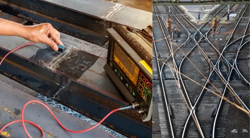
Ultrasonic testing for railways is a pulse-echo search for internal rail flaws: probes at 0°, about 37–45° and 70° ride the rail head on wheels or sleds and send 2.25 to 5 MHz sound into the rail. On Class 4 and 5 track, 49 CFR 213.237(c) requires it every 370 days or 30 million gross tons, whichever comes first.
A test is more than the probes. It is a run by a qualified operator, a coupling film that has to hold for the whole run, a "valid search" the operator can stand behind, and a verification clock that starts the moment the track owner learns of a suspect. This guide follows that process from the probe layout to the marked defect, with a worked test day at the end.
Contents: How UT finds a flaw · Probe layout · Coverage · Test car, hi-rail and cart · Coupling · Equipment checks · Valid search · Verification · Worked example · Rules · Guided wave · Limits · FAQ
How does ultrasonic testing for railways find a flaw?
A probe sends a short pulse of sound into the rail and listens for echoes; a crack, a split or a void sends part of the pulse back early. The time of the echo gives the sound path, so the operator can tell how deep the reflector is and which part of the rail it sits in.
FRA described the method in its 2014 rail integrity rule. The frequency range "normally utilized during current flaw detection operations is 2.25 MHz (million cycles per second) to 5.0 MHz", and the transducers "can be placed at various angles with respect to the rail surface" (79 FR 4234, January 24, 2014, p. 4237). The same preamble names ultrasonic testing as the primary technology on US railroads, with induction testing used as a complement.
The physics in one paragraph: a straight beam (0°) is a longitudinal wave that runs down through the rail and reflects off horizontal surfaces, including the bottom of the base. An angled beam is a refracted shear wave, and it reflects best from flaws that lie across its path, such as a transverse crack in the head. Wave types, refraction and the formulas behind them are covered in our pillar on the science behind ultrasonic testing, so this page stays on how a rail test is actually run.
Why not through-transmission? Through-transmission needs a transmitter on one side of the part and a receiver on the other. Rail in track can only be reached from the running surface at test speed, so in-track rail flaw detection is pulse-echo. The nearest thing to a "through" signal is the 0° back-wall echo from the base: when it drops out, something between the head and the base is blocking the sound, or the probe has lost coupling.
Key takeaway: rail UT is pulse-echo from the head, at roughly 2.25 to 5 MHz, with the probe angle chosen for the flaw orientation.
Which probes does a rail test use, and at what angles?
Each rail gets its own set of probes: a 0° beam for horizontal flaws and back-wall loss, angled beams of about 37–45° for the web and bolt holes, and 70° beams looking forward and backward for transverse flaws in the head. Many systems add side-looking probes for vertical split heads. Exact angles and channel counts vary by manufacturer, so treat the table as typical practice, not a standard.
| Channel | Typical angle | Main targets | What the operator watches for |
|---|---|---|---|
| Straight beam | 0° | Horizontal split head, head and web separation, the horizontal part of a compound fissure, split web | A reflector between the head and the base, or loss of the back-wall (base) echo |
| Web / bolt hole | About 37–45°, forward and backward | Bolt hole cracks, web cracks, angled flaws near joints | An echo next to the expected bolt hole signal, at the crack's position on the hole |
| Head | 70°, forward and backward | Transverse fissures, detail fractures, engine burn fractures, defective welds in the head | A reflector in the head at a sound path that matches the head, seen from one or both directions |
| Side-looking (where fitted) | Angled across the head, toward gauge or field side | Vertical split heads, flaws off the head centerline | An early echo or a lost corner echo |
Two forward-and-backward pairs matter because a crack that faces one way reflects most strongly to the probe looking at it. A transverse defect leaning toward the direction of travel can be weak on the forward 70° and strong on the backward 70°. Seeing it on both channels at the same rail position is also how a test system separates a real reflector from noise.
Wheels or sleds. On test vehicles the probes usually sit inside fluid-filled rubber wheels, called roller search units, that roll on the rail head. One 1999 university report for the Mountain-Plains Consortium describes three to six transducers inside each wheel, usually two wheels per rail, and "a total of as many as 12 transducers per rail" (MPC 99-106, Colorado State University, 1999). Other systems mount the probes in sleds or shoes that slide on the head on a film of water. Both designs aim the beams the same way; they differ in how they hold coupling and how they wear.
The same report labels the angles as longitudinal-wave angles. Rail 70° channels are normally shear wave, so don't reuse its angle calculations.
Key takeaway: ask any provider for its channel list per rail, by angle and direction. It tells you which defect types the system is built to see.
How much of the rail section does the probe set cover?
A standard probe set covers the rail head, the web and the part of the base directly under the web, but not most of the base flanges. FRA's own description is precise: the ultrasonic waves "normally scan the entire rail head and web, as well as the portion of the base directly beneath the web" (79 FR 4234, p. 4237).
The original version of this page said traditional probes can't inspect the lower rail at all. That overstated it. The 0° beam reaches the base under the web on every pulse, which is why loss of the back-wall echo is such a useful channel, and the angled beams sweep the web and bolt holes. What the probes miss is the outer part of the base, the flanges that extend sideways from the web.
A railroad research digest made the same point about field welds. In its thermite weld survey, TTCI wrote that detector-car weld data "is likely skewed as the ultrasonic rail flaw detection process only scans the head and web of the rail, and not the majority of the base" (TTCI Technology Digest TD-00-013, J. Kristan, 2000). FRA's 2014 preamble also names "the base flange area" as a limit of current technology.
| Rail zone | Vehicle or cart probe set | What closes the gap |
|---|---|---|
| Head | Covered by 70°, side-looking and 0° channels, unless surface damage blocks the sound | Hand test from other angles; grinding where shelling or head checks mask the head |
| Web | Covered by 0° and 37–45° channels, including bolt holes inside joint bars | — |
| Base under the web | Covered by the 0° back-wall echo | — |
| Base flanges | Mostly not covered | Hand UT of the base at welds and other targeted locations; visual inspection for broken base |
Key takeaway: the honest coverage statement is "head, web and the base under the web". Where base flange cracks are a known risk, such as at thermite welds, plan hand testing on top of the vehicle run.
How does a test car, hi-rail or walking cart run a test?
All three carry the same kind of probe set; they differ in speed, how suspects are verified, and how the equipment gets on and off the track. FRA's 2014 preamble lists four processes in use: a "portable test process" pushed "at a walking pace"; a "start/stop process" on a vehicle that "tests at a slow speed (normally not exceeding 20 mph)"; a chase-car process, with a lead test vehicle ahead of a verification car; and a continuous process, run non-stop with the data analyzed at a central location and suspects verified later.
| Platform | How it moves | Typical working speed | How suspects are verified |
|---|---|---|---|
| Rail-bound test car | A dedicated vehicle that stays on the rail; needs a track occupancy for the run | Rated to about 30 mph non-stop; stop-and-verify runs average far less (6 to 8 mph in a 1999 report) | Stops and sets back; the operator hand-tests the suspect on the spot |
| Hi-rail test vehicle | A road truck with retractable flanged wheels that sets on and off at crossings | Similar to a test car in stop-and-verify mode | Same as the test car; a chase vehicle may verify on chase-car runs |
| Walking cart | A hand-pushed frame with the probes on sleds, one or both rails | Walking pace (one vendor rates its cart to 5 km/h, about 3 mph) | The operator is already standing at the suspect and verifies it immediately |
| Continuous test vehicle (213.240) | Non-stop at higher speed | Set by the system and the owner's program | Data reviewed by a qualified analyst; suspects field-verified within 36 or 84 hours |
Rail-bound test car
A test car runs under the owner's track authority, usually with a test operator watching the channel display and a driver. The MPC report put the practical pace bluntly: test cars are "capable of speeds up to 30 mph in a non-stop testing mode. However, in practice the vehicle stops frequently to hand verify indications", and so "typically average 6 to 8 mph" (MPC 99-106). When a suspect shows, the car stops, sets back to the location and the operator verifies it with a portable flaw detector.
Hi-rail test vehicle
A hi-rail is defined in 49 CFR 214.7 as a roadway maintenance machine built to Federal Motor Vehicle Safety Standards "equipped with retractable flanged wheels so that the vehicle may travel over the highway or on railroad tracks". Its advantage is access: it can set on at a grade crossing, test a block of track and set off again. Once on the rail it is on-track equipment, so the crew still needs working limits under Part 214 on an FRA railroad. A hi-rail is a platform; the UT system fitted to it has its own probe carriage and its own operator.
Walking cart
A walking cart is a hand-pushed frame with probes on sleds and a water tank that feeds couplant to the probes. A hand-pushed cart is not a roadway maintenance machine under 214.7, which covers devices powered by something other than hand power. The crew still needs on-track protection: under Part 214 on an FRA railroad, or under the agency's program on rail transit (49 CFR Part 671). Carts suit transit systems, yards, short sections, special trackwork approaches and verification work, where a test vehicle is too large or the possession is too short. Their trade-off is speed, so a cart is a poor fit for long main-line segments.
For the choice between platforms on a given job, see our comparison of hi-rail trucks and inspection carts.
Key takeaway: rated speed isn't test speed. Plan a stop-and-verify run on its average speed, including stops, not on the vehicle's rated maximum.
How is the probe coupled to the rail?
Sound can't cross an air gap, so every probe needs a liquid film between it and the rail head for the whole run. Wheels hold a fluid inside the tire and need a wet contact with the rail; sleds slide on a film of water fed from a tank. The MPC report notes that the coupling fluid applied at the wheel-rail contact "usually is oil- or water-based".
The operator watches coupling all the time, usually through the 0° back-wall echo. A strong, steady base echo means sound is entering the rail and reaching the bottom. When the back-wall echo drops out along a stretch, either something inside the rail is blocking the beam or the probe has lost contact, and the operator has to decide which.
What breaks coupling in the field:
- Heavy lubrication or debris on the head. FRA's preamble lists "heavy lubrication or debris on the rail head" beside the surface conditions that degrade detection. Lubricated curves are a common cause of untested stretches.
- Rough or damaged running surfaces. Shells, engine burns, spalling, flaking, corrugation and head checks scatter or block the sound, so the beam never reaches the flaw beneath them.
- Worn or tilted heads. A worn head profile changes the angle at which the beam enters the rail. A TTCI digest on worn rail warned that "the wrong volume of material is inspected" (TD-16-030).
- Freezing, heat and water supply. The couplant has to stay liquid and keep flowing; the procedure should say what the crew uses in cold weather.
Couplant choice for rail work is covered in more depth in ultrasonic couplant for rail inspection.
Key takeaway: lost coupling is untested rail, not a false call. It has to be logged and dealt with under 213.237(g) and (h).
How is the equipment checked before and during a run?
Part 213 sets no calibration method for rail flaw equipment; it makes the qualified operator responsible for determining that the equipment "is performing as intended" (213.238(b)(2)). How that is shown comes from the provider's procedure and the owner's contract.
In typical practice, a test vehicle or cart is run over a test rail, sometimes called a reference rail, that holds artificial reflectors such as drilled holes and saw cuts at known positions. The check is usually made at the start of a shift and often again at the end, so the day's data is bracketed by two known-good runs. No public US primary source describes a standard reference rail design, so treat this as common practice that the contract should spell out.
Europe has written it down. EN 16729-1, the European standard for ultrasonic testing of rails in track, carries a section on detection of reference reflectors and an annex on artificial reflectors in reference rails (public store listings; the text is paywalled). A 2026 revision is in draft.
The portable flaw detector used to verify suspects is set up separately, on standard reference blocks for range and angle and on a sensitivity reference set by the procedure. Our calibration guide for rail inspection RFPs lists what to ask a provider to show.
What about AREMA? AREMA is an industry association, not a regulator. A TTCI digest from 1999 records that a "Recommended Minimum Performance Guideline for Rail Testing" was added to the AREMA Manual for Railway Engineering in 1992, as Section 2.2, with detection targets grouped by tonnage (TTCI TD-99-006, Garcia and Reiff, 1999). Its current location in the manual is not confirmed here, and the manual is paywalled. Nothing public shows AREMA promoting guided-wave or "bulk wave" testing for routine rail inspection, as the original version of this page claimed.
Key takeaway: put the check routine in the contract: which reference rail, how often, what the pass criteria are, and how a failed check affects the data since the last good one.
What makes a search "valid" under 213.237?
A valid search is a continuous internal inspection in which the equipment works as intended and a qualified operator interprets the responses. The definition is in 49 CFR 213.237(j)(4):
"Valid search means a continuous inspection for internal rail defects where the equipment performs as intended and equipment responses are interpreted by a qualified operator as defined in § 213.238."
Section 213.238(b)(4) adds the operator's duty to determine that each valid search "is continuous throughout the area inspected and has not been compromised due to environmental contamination, rail conditions, or equipment malfunction." In practice that is the coupling and surface-condition judgment described above, made foot by foot along the run.
Where the operator decides a valid search couldn't be made, that length "may not be considered as internally inspected" (213.237(g)). Before the time or tonnage limit runs out, the owner must do one of three things under 213.237(h):
- Conduct a valid search.
- Reduce operating speed to a maximum of 25 mph until a valid search can be made.
- Replace the rail that wasn't inspected.
The location of any track not tested is part of the inspection record under 213.241(c)(6). The 25 mph figure is a limit on trains over the untested rail; it has nothing to do with how fast the test vehicle runs.
Key takeaway: the deliverable that matters most on test day, after the defect list, is the list of untested stretches with mileposts and rails.
How are suspects verified and marked?
When the track owner learns of an indication, 213.113(b) requires it to be verified within four hours, or immediately if the owner has an indication of a defect needing remedial action A, A2 or B. The rule reads:
"Except as provided in § 213.240, the track owner must verify the indication within four hours, unless the track owner has an indication of the existence of a defect that requires remedial action A, A2, or B identified in the table contained in paragraph (c) of this section, in which case the track owner must immediately verify the indication."
The clock runs from when the owner learns of the indication, so the contract should say who the operator calls and how. On a stop-and-verify run the call and the verification usually happen within minutes of each other.
Verification steps, in typical order:
- Stop and return to the suspect location; confirm the milepost and rail.
- Clean the head and check the surface for visible cracks, burns or shelling.
- Hand-test with a portable flaw detector, using the angles that fit the suspect (70° from both directions for a head suspect, 0° and 37–45° for web and bolt hole suspects).
- Classify the result: a defect type from the 213.113 table with its size (percent of head area for transverse defects, inches for split heads and bolt hole cracks), or a benign reflector such as a bolt hole, a weld upset, a drilling or a rail end.
- Mark the defective rail.
- Pass the type, size and location to the owner's person designated under 213.7, who decides whether the track may stay in use and applies the remedial action.
Marking has its own rule. Under 213.237(e), each defective rail is marked "with a highly visible marking on both sides of the web and base", or on or next to the head where permanent features block those surfaces. Under 213.113(a), trains may not run over the defect until the rail is replaced or repaired, or the remedial action from the table is started. The remedial action table and its lettered notes are explained in our guide to FRA defect codes.
Continuous testing is the exception. An owner using continuous rail testing under 213.240 is exempt from 213.113(b). Suspects must instead be field-verified within 84 hours, or 36 hours for a suspected A, A2 or B defect. Section 213.240(e)(4) adds: "A suspect location is not considered a defect under § 213.113(c) until it has been field-verified by a person qualified under § 213.238."
Key takeaway: the operator finds and verifies; the owner's designated person disposes. Keep those roles separate in the contract and the report.
Worked example: one test day over 40 miles
This example is hypothetical. It follows one stop-and-verify test day and tracks three numbers: miles validly tested, suspects found, and the verification clock on each.
Inputs:
- Class 4 freight subdivision, single track, MP 210.0 to MP 250.0: 40.0 track-miles, which is 80.0 rail-miles.
- Traffic: 24 MGT a year. Last valid search of the whole segment: December 1, 2025.
- Test date: Tuesday, November 10, 2026. Stop-and-verify run under exclusive track occupancy.
- Assumed moving test speed between stops: 10 mph.
- The owner's contact rides along or is on the radio, so the owner learns of each suspect when it is found.
The day
| Time | Event |
|---|---|
| 07:00 | Job briefing; track authority received |
| 07:20 | Equipment check on the test rail: all channels see their reference reflectors |
| 07:45 | Test starts at MP 210.0 |
| 08:05–13:46 | Eight suspects found and verified (table below) |
| Through the day | Two stretches logged as untested (table below) |
| 14:10 | Test ends at MP 250.0 |
| 14:25 | End-of-shift check on the test rail: all channels pass |
| 15:00 | Defect list and untested-track list sent to the owner |
The suspects and the clock
| # | Found | MP and rail | Channel | Deadline | Verified | Minutes used | Result |
|---|---|---|---|---|---|---|---|
| 1 | 08:05 | 213.3 right | 70° forward | 12:05 | 08:22 | 17 | Detail fracture, 15% of head area: action C |
| 2 | 08:55 | 218.3 left | 37° at a joint | 12:55 | 09:08 | 13 | Benign: bolt hole geometry, no crack |
| 3 | 09:40 | 223.3 right | 0° back-wall loss at a field weld | 13:40 | 09:53 | 13 | Benign: weld upset and finish |
| 4 | 10:31 | 229.3 left | 70° both directions and 0°, large | Immediately | 10:39 | 8 | Transverse fissure, 65% of head area: A2, or E and H |
| 5 | 11:25 | 233.3 right | 70° forward | 15:25 | 11:38 | 13 | Benign: engine burn on the surface, no internal fracture |
| 6 | 12:04 | 237.3 left | 70° backward | 16:04 | 12:21 | 17 | Transverse fissure, 30% of head area: action D |
| 7 | 12:54 | 242.3 right | 37° in the web | 16:54 | 13:07 | 13 | Benign: drilled bond-wire hole |
| 8 | 13:33 | 246.3 left | 0° | 17:33 | 13:46 | 13 | Benign: rail end at an insulated joint |
The remedial letters come from the 213.113(c) table for transverse fissures and detail fractures: 5% to less than 25% of head area is C, 25% to less than 60% is D, and 60% to less than 100% is A2, or E and H. Suspect 4 shows why the "immediately" branch exists. A large reflector seen on several channels already points to a defect in the A2 band, so the crew stopped at once instead of using the four-hour window.
Untested track
| Stretch | Rails | Cause | Rail-miles |
|---|---|---|---|
| MP 231.0–231.2 | High rail of the curve only | Heavy flange lubrication; coupling lost | 0.20 |
| MP 244.6–244.7 | Both rails | Shelling blocked the 70° and 0° channels | 0.20 (0.10 × 2) |
| Total | 0.40 |
The numbers, checked
- Suspects: 8 found, 3 verified defects (1, 4 and 6), 5 benign.
- Verification clock: every suspect was verified inside its window. The most time used on a four-hour suspect was 17 minutes (suspects 1 and 6); suspect 4 was verified 8 minutes after it was found.
- Time on track: 07:45 to 14:10 is 6 h 25 min, or 385 minutes. The eight stops took 20, 15, 15, 30, 15, 20, 15 and 15 minutes, a total of 145 minutes. That leaves 240 minutes (4.0 h) of moving test time, and 4.0 h at 10 mph is 40.0 miles, which matches the segment.
- Average speed: 40.0 miles in 6.42 h is about 6.2 mph, close to the 6 to 8 mph the MPC report gives for stop-and-verify runs.
- Valid search: 80.0 − 0.40 = 79.60 rail-miles, or 99.5% of the rail.
- The untested 0.40 rail-miles: it still runs on the December 1, 2025 search. The calendar limit is 370 days, so the deadline is December 6, 2026. Tonnage since that search is about 24 × 344 / 365 = 22.6 MGT, under 30, so the calendar date controls. The owner has 26 days from test day to re-search the two stretches (after grinding the shelled one, for example), hold trains to 25 mph over them, or replace the rail.
- Next full test: at 24 MGT a year, 30 MGT takes 30 / 24 × 365 = 456 days, longer than 370. So the calendar limit controls again, and the next test of the segment is due by November 15, 2027.
Key takeaway: a good test-day report gives all three numbers: rail-miles validly searched, suspects with their verification times, and untested stretches with their deadlines.
Which rules frame a rail ultrasonic test?
Five sections of Part 213 frame the job: 213.237 sets the interval and the valid search, 213.238 qualifies the operator, 213.113 sets verification and remedial action, 213.240 offers continuous testing as an alternative, and 213.241 sets the records. Section 213.237 requires "internal rail inspections" with equipment that can detect defects between joint bars (213.237(f)). It names no test method; ultrasonic testing is the industry's way of meeting it.
| Track | Maximum interval between internal rail inspections, 213.237(c) |
|---|---|
| Class 4 and 5 | 370 days or 30 MGT, whichever is shorter |
| Class 3 with regularly scheduled passenger trains, or a hazardous materials route | 370 days or 30 MGT, whichever is shorter |
| Other Class 3 | Once each calendar year (no more than 18 months apart) or once every 30 MGT, whichever is longer, never more than 5 years apart |
| Class 6 and higher | At least twice a year, at least 120 days apart (213.339) |
There is no 213.237 interval for Class 1 and 2 track. The original version of this page said some areas are tested "monthly" and others "annually"; neither figure comes from the rule. For how owners set intervals between these limits, see how often rail must be tested, and for each paragraph of the rule, our 49 CFR 213.237 guide.
Operator qualification (213.238). The provider of rail flaw detection must have a documented training program and must identify the equipment types each operator is qualified on. A qualified operator is trained and has written authorization from the employer to:
- conduct a valid search with the specific equipment types he or she is qualified on;
- determine that the equipment is performing as intended;
- interpret equipment responses and take action under the employer's procedures; and
- determine that each search is continuous and not compromised by contamination, rail conditions or equipment malfunction.
Initial qualification needs at least 160 hours of rail flaw detection experience under the direct supervision of a qualified operator or the equipment manufacturer's representative, plus demonstrated proficiency. Section 213.237(i) adds that the operator must have shown proficiency on each type of equipment he or she is assigned. FRA doesn't certify rail flaw operators; the employer qualifies them.
Records (213.241). The inspection record lists the date, the track and its limits, the location, type and size of each defect not removed before the next train, the initial remedial action and its date, and any track not tested. Records are kept for two years after the inspection and one year after remedial action, whichever is later.
Transit. Rapid transit not connected to the general railroad system falls outside Part 213 (213.3(b)), under FTA rules and the state safety oversight agency, so the interval and valid-search rules come from the agency's own program and contract.
Key takeaway: the rule sets intervals, people, verification and records; the probe layout and calibration routine come from the provider's procedure and the owner's contract.
Where does guided wave testing fit?
Guided wave testing is a niche in rail: it is used for broken-rail monitoring and research, not for routine 213.237 searches. Guided waves travel along the rail rather than across it, so one permanently mounted transducer can watch a long length for a complete break. A permanently installed broken-rail detection system on South Africa's Sishen–Saldanha line is the best-known example (Ramatlo et al., MATEC Web of Conferences 347, 2021).
FRA has funded guided-wave research aimed at seeing transverse cracks under surface shelling, but that work hasn't replaced the pulse-echo probe set on test vehicles. Guided wave and "long-range UT" are the same method under two names, not competing methods. More on the technique is in our guided wave ultrasonic testing article.
What rail ultrasonic testing can't do
Rail UT finds most internal head and web defects, but it misses some flaws and can't search some rail at all. These are the limits that matter when planning a program:
- Most of the base flange. The probe set covers the base under the web, not the flanges. Base cracks at thermite welds need hand testing.
- Masking by surface damage. Shells and head checks block or scatter the beam. They mask detail fractures most, because detail fractures start from shelled spots and head checks. Grinding can restore a valid test.
- Small defects. No test finds everything. In TTCI's 1998 benchmark trials of six hi-rail systems on 49 known defects, the systems found 72% overall, and fewer of the small transverse defects (TD-99-006). Detection rates and their limits are covered in detail on our ultrasonic rail testing capabilities page.
- Special trackwork. Cast manganese frogs scatter sound badly and are examined visually in service; 213.237 doesn't mention frogs or switch points.
- No defect size from the vehicle. The vehicle flags a suspect; the size used for remedial action comes from hand verification.
- Grooved rail. Embedded street-running rail needs equipment built for the groove; the European in-track standard EN 16729-1 doesn't cover it.
Key takeaway: state coverage and limits in the test report so the owner knows what the search didn't see.
How EMA Industries applies this
EMA Industries provides ultrasonic rail flaw testing for transit agencies, short lines and industrial track owners, along with rail weld inspection. We are based in Southern California and mobilize nationwide. For each job we agree the test method, the equipment check routine, the call path for suspects and the untested-track reporting before the first run. To see what happens from quote to final records, read what to expect from ultrasonic railroad testing services, or contact us with your segment list and track classes.
Frequently asked questions
How fast does an ultrasonic rail test vehicle go?
Test vehicles are rated to about 30 mph in non-stop mode, but stop-and-verify runs average far less. One 1999 report put the practical average at 6 to 8 mph, because the vehicle stops to hand-verify each suspect. FRA's 2014 rule described start/stop testing as "normally not exceeding 20 mph", and walking carts move at walking pace.
Does ultrasonic rail testing inspect the rail base?
It inspects only part of it. The 0° beam covers the base directly beneath the web, but most of the base flange isn't scanned by a test vehicle or cart. Where base cracks are a concern, such as at thermite welds, the base is tested by hand.
Who is allowed to operate rail flaw detection equipment?
A qualified operator under 49 CFR 213.238: someone trained under the provider's documented program, with written employer authorization and at least 160 hours of supervised rail flaw detection experience. The employer qualifies the operator; FRA doesn't issue a certificate.
What happens when a test car finds a suspect?
The operator stops and verifies it by hand. Under 213.113(b) the owner must verify an indication within four hours of learning of it, or immediately if it points to a defect needing remedial action A, A2 or B. A verified defect is marked on the web and base, and the owner's designated person decides on the remedial action.
Sources
- 49 CFR 213.237, Inspection of rail: eCFR (text read on Cornell LII, October 2026)
- 49 CFR 213.238, Qualified operator: eCFR
- 49 CFR 213.113, Defective rails: eCFR
- 49 CFR 213.240, Continuous rail testing: eCFR
- 49 CFR 213.241, Inspection records: eCFR
- 49 CFR 213.339, Inspection of rail in service (Class 6 and higher): eCFR
- 49 CFR 214.7, Definitions (hi-rail vehicle, roadway maintenance machine): eCFR
- FRA, Track Safety Standards; Improving Rail Integrity, final rule, 79 FR 4234, January 24, 2014: govinfo PDF
- B. D. Jeffrey and M. L. Peterson, Assessment of Rail Flaw Inspection Data, MPC Report 99-106, Colorado State University, August 1999: ugpti.org
- J. Kristan, Thermite Weld Failure Survey, TTCI Technology Digest TD-00-013, July 2000: mxvrail.com
- G. A. Garcia and R. P. Reiff, Benchmarking Results of North American Rail-Flaw Detection Technologies, TTCI Technology Digest TD-99-006, February 1999: mxvrail.com
- TTCI Technology Digest TD-16-030 (ultrasonic inspection of worn rail): mxvrail.com
- Ramatlo, Loveday, Long and Wilke, guided-wave broken rail detection, MATEC Web of Conferences 347:00034, 2021: doi.org
- EN 16729-1, Railway applications: Infrastructure: Non-destructive testing on rails in track, Part 1 (ultrasonic testing): AFNOR store listing