Ever wondered how invisible cracks and flaws inside metal welds are detected without cutting them open? Shear wave ultrasonic testing is a powerful method under the broader category of ultrasonic testing that makes this possible.
This article breaks down how shear wave UT works, why it’s used, and how it compares to other weld inspection techniques. Whether you’re new to NDT or refining your inspection skills, you’ll find clear, practical insights throughout.
Basics of Ultrasonic Testing
Ultrasonic Testing (UT) is one of the most trusted non-destructive testing (NDT) methods used in industries like construction, aerospace, oil and gas, and manufacturing. It uses high-frequency sound waves to detect internal flaws without damaging the material being inspected.
How Ultrasonic Testing Works
The principle is simple but powerful. A transducer emits ultrasonic waves into a material. These waves travel through the material and reflect back when they hit a boundary like a crack or void. The reflected signals are then analyzed to identify the location and size of the defect.
Key elements involved:
- A transducer to generate and receive ultrasonic waves
- A couplant (gel or liquid) to help transmit sound waves into the material
- A flaw detector to display the signals received
Why It’s So Effective for Flaw Detection
Ultrasonic Testing is known for its accuracy in locating internal flaws that are not visible to the naked eye. It can detect issues like:
- Cracks
- Voids
- Inclusions
- Lack of fusion in welds
It’s especially useful in critical components where structural failure is not an option.
But not all ultrasonic methods are the same and some are better suited for welds than others. That’s where shear wave ultrasonic testing steps in.
What Is Shear Wave Ultrasonic Testing?
Shear wave ultrasonic testing is a type of angle beam ultrasonic inspection where sound waves are introduced into the material at an angle. Instead of using straight (longitudinal) waves that travel directly through the material, this method uses shear waves that move side to side, ideal for finding flaws parallel to the surface, like those found in welds.
Its main goal? To inspect welds and joints more effectively by increasing flaw detection accuracy in critical zones.
Shear Waves vs. Longitudinal Waves
When performing ultrasonic testing, two primary types of sound waves are used. longitudinal waves and shear waves. Each type behaves differently within the material and serves a different inspection purpose.
Particle Movement
Longitudinal waves move particles in the same direction as the wave is traveling. This straight-line motion makes them suitable for detecting flaws directly beneath the probe.
In contrast, shear waves move particles side to side, at a 90-degree angle to the wave’s travel direction. This sideways motion makes shear waves more effective at picking up flaws that run parallel to a surface like those found in weld seams.
Speed of Propagation
Longitudinal waves travel faster through a material than shear waves. Because of their speed, they’re often used for quick scans or in thick, homogenous materials. Shear waves, although slower, provide more detailed information near surfaces and along weld joints where critical defects often form.
Best Use Cases
Longitudinal waves are ideal for simple, thick materials where deep internal flaws are the main concern. But when it comes to weld inspection, shear wave ultrasonic testing is more effective. It’s specifically designed to reveal surface-near or side-oriented defects like lack of fusion or cracks that aren’t easily detected by straight-beam methods.
Entry Angle
In ultrasonic testing, the angle at which waves enter the material affects what areas they can inspect. Longitudinal waves are typically introduced straight on, at a 0° angle.
Shear waves, however, are introduced using angled probes commonly at 45°, 60°, or 70°. These angled beams help the waves reflect off flaws at critical orientations, increasing the chances of detection.
Why Choose Shear Waves?
Advantages of shear wave ultrasonic testing:
- Better detection of side-oriented flaws, such as lack of fusion in welds
- Ideal for complex geometries and joints
- Works well on materials with varying thickness
- Provides high-resolution images of flaws
These benefits make shear wave ultrasonic testing a top choice for ultrasonic weld inspection
Angle Beam Ultrasonic Testing
When it comes to shear wave ultrasonic testing, the angle beam technique is at the core of how the inspection works. Rather than sending sound waves straight into the material, the transducer is angled using a wedge to direct waves diagonally. This approach helps target flaws that run along or just below the surface, such as those found in welds and joints.
How Angle Beam Probes Generate Shear Waves
The process starts with a transducer mounted on a wedge (also called a “probe holder” or “shoe”). When the transducer sends longitudinal waves into the wedge, the angled contact surface converts them into shear waves as they enter the test material. This conversion happens due to refraction, much like how light bends when passing through water.
In simple terms:
- The transducer produces sound waves.
- The wedge angles the waves into the material.
- Refraction converts longitudinal waves into shear waves.
- Shear waves then move through the material at an angle.
This allows inspectors to examine welds and other challenging areas that straight beams can’t reach effectively.
Common Probe Angles
To suit different inspection needs, various wedge angles are used. The most common are:
- 45° – Useful for general weld inspections.
- 60° – Common in thicker materials or when better flaw reflection is needed.
- 70° – Ideal for scanning root and toe areas of welds.
Each angle offers a different inspection path and sensitivity, depending on the geometry of the weld and expected flaw location.
But the angle alone isn’t enough, you also need the right tools and materials to generate clear, reliable results. Let’s look at the key equipment that makes shear wave ultrasonic testing possible.
Equipment Used in Shear Wave UT
High-quality ultrasonic testing depends not only on techniques but also on the equipment used. For shear wave ultrasonic testing, this involves a combination of components working together to generate, transmit, and receive signals accurately.
Components of Angle Beam Assemblies
The two essential parts of an angle beam setup are:
- Transducer: The source of ultrasonic waves.
- Wedge (or Probe Holder): Guides the sound waves into the material at a specific angle and facilitates the conversion to shear waves.
Together, they form the angle beam probe, which is held firmly against the test surface during scanning.
Choosing the Right Probes and Wedges
Selecting the correct probe setup is critical for accurate results. Key factors include:
- Frequency: Higher frequencies offer better resolution but shallower penetration.
- Material Thickness: Thicker parts may require lower-frequency probes.
- Weld Configuration: The shape and size of the weld help determine the appropriate wedge angle.
- Flaw Orientation: Certain flaws reflect better at specific angles, so matching the wedge angle to flaw orientation improves detection.
Always match your equipment to the inspection goal for best results.
Role of Couplants
No matter how good the probe setup is, signal transmission won’t happen without a proper couplant. This gel or liquid eliminates the air gap between the wedge and the test surface, ensuring ultrasonic waves pass efficiently into the material.
Why couplants matter:
- They improve contact between the probe and material.
- They prevent signal loss caused by air pockets.
- They ensure consistent wave travel and reflection.
With the right angle, the right probe, and the right couplant, your inspection setup is ready. But how do you interpret the signals and detect flaws in real-world scenarios? Let’s move into the application side of shear wave ultrasonic testing in weld inspection.
Applications in Weld Inspection
One of the most common and valuable uses of shear wave ultrasonic testing is in weld inspection. Because welds often contain flaws that form along the fusion lines or within the weld body itself, a testing method that can inspect angled surfaces is essential. That’s where shear wave UT stands out.
Detecting Weld Defects
Shear waves are particularly effective at identifying defects that are not visible from the surface. These include:
- Lack of fusion – when the weld metal does not properly bond with the base metal.
- Cracks – either surface-breaking or internal, these can severely weaken a weld.
- Porosity – small gas pockets that affect the integrity of the weld.
These flaws often develop at orientations that reflect angled waves better than straight ones, making angle beam shear wave ultrasonic testing the ideal choice.
Versatility Across Weld Types
Another strength of this method is its ability to adapt to various weld geometries and materials. Whether you’re inspecting:
- Butt welds
- T-joints
- Fillet welds
- Nozzle welds in pressure vessels
Shear wave probes can be angled to scan across the weld in multiple passes, increasing the chance of detecting critical flaws.
Materials Inspected
This technique is not limited to one material type. It works well with:
- Carbon steel
- Stainless steel
- Aluminum alloys
- Dissimilar metal welds
But beyond weld inspections, what makes shear wave ultrasonic testing so reliable and widely adopted? The answer lies in the distinct advantages it offers over other NDT methods.
Advantages of Shear Wave Ultrasonic Testing
Compared to many other ultrasonic testing techniques, shear wave UT brings a unique set of benefits, especially for industries that require accurate, reliable, and non-destructive flaw detection.
Better Detection of Angled Flaws
Flaws that are perpendicular or angled to the surface often go undetected in traditional straight-beam testing. Shear waves, with their side-to-side motion and angled entry, are much more likely to reflect off these flaws and send signals back to the receiver.
This leads to:
- Higher detection probability
- Reduced risk of missed defects
- More accurate sizing and location of flaws
Effective in Complex Geometries
Structures with irregular shapes, joints, or curved surfaces are notoriously hard to inspect. Shear wave probes, with adjustable angles and flexible scanning patterns, can reach areas that other methods cannot.
Ideal for:
- Welds in pipelines
- Nozzle-to-shell joints
- Thick-walled components with variable cross-sections
Non-Destructive and Material-Safe
Perhaps one of the greatest strengths of shear wave ultrasonic testing is that it does not alter, damage, or weaken the component being inspected.
- No cutting, no stress, no cleanup
- Safe for use during production or maintenance
- Can be repeated regularly without affecting integrity
With these clear advantages, it’s no wonder that shear wave UT has become a trusted technique across industries.
Limitations and Considerations
While shear wave ultrasonic testing offers powerful benefits, it’s not without its challenges. Like any testing method, it has limitations that must be understood to ensure accurate and reliable inspections.
Difficulties with Coarse-Grained or Austenitic Materials
Materials with coarse grains or complex internal structures, such as austenitic stainless steels, can scatter or distort ultrasonic signals. This can make flaw detection less reliable and interpretation more difficult.
Why it matters:
- Coarse grains cause wave scattering.
- Signal-to-noise ratio drops, reducing clarity.
- Interpretation of reflections becomes less certain.
In such cases, alternative UT techniques or complementary NDT methods may be necessary.
Skilled Interpretation Required
Ultrasonic testing, especially with angle beam shear waves, demands a high level of skill and training. Interpreting signals correctly involves understanding how flaws reflect waves and how sound paths vary with geometry and materials.
Common challenges for operators:
- Differentiating between flaw echoes and geometric indications
- Adjusting probe angle to suit weld geometry
- Evaluating signal amplitude and travel time
Without adequate experience, even the best equipment can lead to missed or false indications.
Signal Loss at High Frequencies or Extreme Angles
Shear waves may lose energy when traveling at higher frequencies or when introduced at steep angles (e.g., 70°). This can reduce flaw detection depth and limit effectiveness in thicker or denser materials.
What to watch for:
- Attenuation (gradual weakening of the signal)
- Limited penetration in thick components
- Reduced sensitivity at greater depths
Operators may need to adjust probe frequency or choose different angles based on the material and inspection depth.
Despite these challenges, proper technique, equipment selection, and training can overcome many of these limitations.
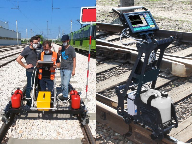
Overall, shear wave ultrasonic testing uncovers hidden rail flaws that other methods might miss. Our ultrasonic examination services provide precise detection, while our Level III services ensure expert oversight for accurate and compliant inspections. Keep your railway infrastructure safe with our professional NDT solutions.
Conclusion
Shear wave ultrasonic testing is a powerful tool in the world of ultrasonic testing, especially when it comes to detecting hidden flaws in welds and complex structures. Its ability to direct sound waves at angles gives inspectors a clearer view beneath the surface, without damaging the material.
From its role in weld inspections to the benefits of better flaw detection and material coverage, shear wave UT has become essential in industries where safety and reliability matter most. However, like any method, it comes with limitations that require skilled operators and proper equipment choices.
By understanding both its strengths and challenges, companies can apply shear wave UT more effectively and with greater confidence. As technology advances, expect even more precision, portability, and automation in this field of testing.
Key Points
- Shear wave ultrasonic testing (UT) uses angled sound waves to detect internal flaws in materials, especially useful for weld inspection.
- Ultrasonic testing works by sending high-frequency sound waves into a material and analyzing their reflections to identify flaws like cracks or porosity.
- Shear waves move particles perpendicular to the wave direction, offering better detection of flaws that are angled or perpendicular to the surface.
- Shear wave UT is more effective than longitudinal waves in detecting weld defects such as lack of fusion, cracks, and porosity.
- Angle beam ultrasonic testing uses probes that introduce sound at specific angles (commonly 45°, 60°, or 70°) to generate shear waves.
- Essential components for shear wave UT include a transducer, wedge, and couplant—all of which must be selected based on the material and geometry.
- Applications in weld inspection span multiple weld types and materials, including carbon steel, stainless steel, and aluminum.
- Advantages of shear wave UT include enhanced flaw detection, better coverage of complex geometries, and its non-destructive nature.
- Limitations include difficulties with coarse-grained or austenitic materials, signal loss at high frequencies, and the need for skilled interpretation.
- Despite its challenges, shear wave ultrasonic testing remains a highly valuable technique in modern NDT practices, offering reliable and repeatable inspection results.
FAQs
How are probe angles selected in shear wave ultrasonic testing?
Common probe angles are 45°, 60°, and 70°. The choice depends on factors such as material thickness, weld geometry, and the specific type of flaw being targeted. Selecting the appropriate angle ensures optimal flaw detection.
Can shear wave ultrasonic testing be used on painted or coated surfaces?
Yes, provided the coating is well-bonded and free from air bubbles. However, thick or uneven coatings may affect the transmission of sound waves, potentially impacting the accuracy of the test.
What qualifications are required to perform shear wave ultrasonic testing?
Operators typically need certification in ultrasonic testing, often at Level II or III, depending on industry standards. Training covers equipment handling, interpretation of results, and understanding of material behaviors to ensure accurate and reliable inspections.