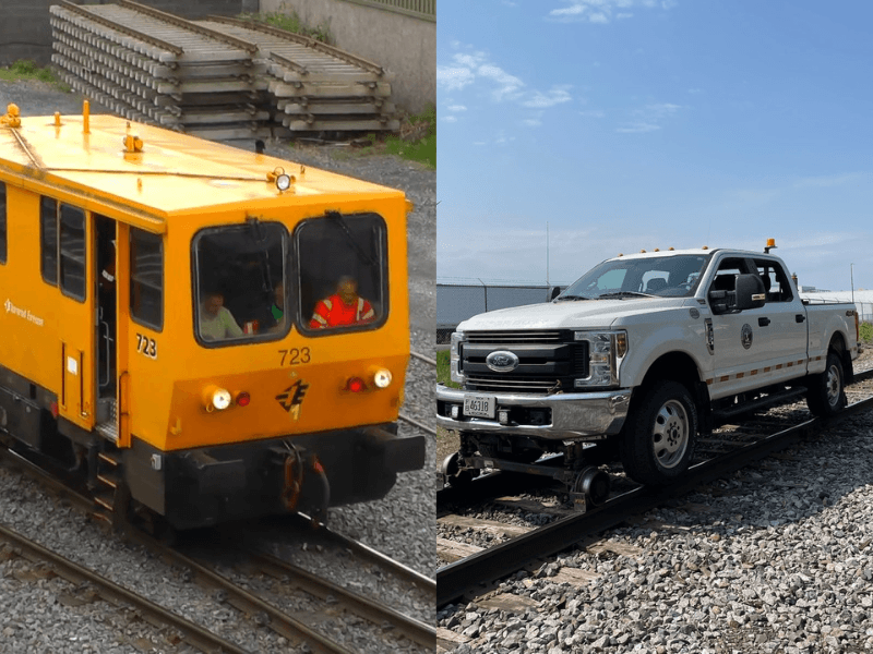
A railway inspection car is a rail-bound vehicle that measures the track or tests the rail while it moves, then hands crews a list of locations to verify. The four main types are track geometry cars (49 CFR 213.333), ultrasonic rail test cars (213.237), gage restraint measurement systems (213.110) and vision or laser systems.
Each type answers a different question. A geometry car asks whether the track is in the right place. A rail test car asks whether there is a crack inside the rail. A GRMS car asks whether the ties and fasteners can hold gage under load. A vision system asks what the track components look like. None of them repairs anything. Their value lies in the exception report and in what the railroad does with it in the hours and days afterward.
This guide is for track supervisors, transit maintenance-of-way engineers and short-line owners who need to know what each car produces, which FRA rule it serves, and what the rule makes them do once the data arrives. Choosing between a rail-bound car, a hi-rail truck and a walking cart is a separate decision, covered in our guide to hi-rail truck vs inspection cart. The person who rides the truck and does the visual inspection is covered in what a hi-rail track inspector does.
Contents: Types at a glance · Geometry cars · Ultrasonic test cars · GRMS · Vision and laser · Acting on the data · Limits · FAQ
Which types of railway inspection car are used, and what does each measure?
Four families of rail-bound inspection equipment do most of the work, and only some of them are tied to a specific FRA rule. The table below sets out what each measures, what it hands over, and where it sits in 49 CFR Part 213.
| Type | What it measures | What it produces | FRA rule it serves |
|---|---|---|---|
| Track geometry car (TGMS) | Gage, alinement, curvature and elevation, surface (profile, crosslevel, warp) under load | Continuous plot on a distance axis, plus an exception report against the class of track | Required by 213.333 on Class 6+ and on Class 1–5 above 5 in. cant deficiency; voluntary elsewhere |
| Ultrasonic rail test car | Internal rail defects in the head and web | Suspect locations, channel maps (B-scan style) and A-scans, then verified defects | The internal rail inspections required by 213.237 (Class 3–5) and 213.339 (Class 6+) |
| Gage restraint measurement system (GRMS) | Gage widening under a set lateral and vertical load | Traces and exception reports of UTG, LTG, PLG24 and GWP | Optional route to tie and fastener compliance under 213.110; required on Class 8–9 by 213.333(h) |
| Vision and laser systems | Images and profiles of ties, fasteners, joint bars, switches and the rail head | Flagged images, measurements and component exception lists | Supplements visual inspection under 213.233(b); performance rules only for concrete ties under 213.234 |
Several systems often share one vehicle. FRA's own Automated Track Inspection Program (ATIP) is described in an FRA research report as using "machine vision inspection technology along with Track Geometry Measurement and Gage Restraint Measurement Systems to thoroughly evaluate track." In its 2024 proposed geometry rule, FRA said its ATIP fleet conducts compliance surveys "on over 150,000 miles of track annually."
None of these cars replaces the visual inspection under 213.233. Part 213 still requires a person designated under 213.7 to inspect the track on foot or from a vehicle at the 213.233(c) frequency, whatever else the railroad runs over it.
Key takeaway: identify the question each car answers before you buy or schedule it; geometry, internal rail condition, lateral restraint and component condition are four different questions.
What does a track geometry car measure, and when does FRA require one?
A track geometry car measures the shape of the track under load and compares it, foot by foot, with the limits for the class of track. FRA calls a qualifying system a Track Geometry Measurement System (TGMS) and sets its design and use rules in 49 CFR 213.333.
What a TGMS must be able to do
Under 213.333(b), a qualifying TGMS must:
- take measurements no more than 3 feet from the contact point of wheels carrying at least 10 kips (10,000 lb) per wheel, unless FRA approves otherwise, so the track is measured loaded;
- record on a distance-based sampling interval, "preferably at 1 foot not exceeding 2 feet";
- repeat itself: values on repeated runs at the same site and speed "shall not differ … more than 1/8 inch."
For Class 1–5 track at more than 5 inches of cant deficiency, the system must measure for gage (213.53), alinement (213.55(b)), curves, elevation and speed (213.57), surface (213.63) and combined alinement and surface deviations (213.65). For Class 6–9, the matching Subpart G sections apply (213.323 to 213.332).
When a geometry car is required
| Track | Required TGMS frequency (213.333(a)) |
|---|---|
| Class 1–5, only for operations at a qualified cant deficiency (Eu) over 5 in. | At least twice per calendar year, not less than 120 days apart |
| Class 6 | At least once per calendar year, not less than 170 days apart (twice, 120 days apart, above 5 in. Eu) |
| Class 7 | At least twice within any 120-day period, not less than 25 days apart |
| Class 8 and 9 | At least twice within any 60-day period, not less than 12 days apart |
Most freight and transit track never triggers this table, because it runs at Class 1–5 speeds without high cant deficiency. That doesn't mean geometry cars are rare. In its October 2024 proposed rule, FRA said that "all 64 railroads covered by this proposed rulemaking are already voluntarily performing TGMS inspections at or above the frequency that would be required by the NPRM." That proposal (new 213.236, docket FRA-2024-0032) would require TGMS runs three times in any 365 days on busier Class 1–5 main track for Class I and II, intercity passenger and commuter railroads. As of this writing no final rule has been confirmed, so treat it as a proposal.
What the geometry data looks like
The output under 213.333(d) is two documents, produced within 24 hours of the run:
- a continuous plot of every measured parameter on a constant-distance axis;
- an exception report: a "systematic listing of all track geometry conditions which constitute an exception to the class of track over the segment surveyed."
The report must carry enough location information for field forces "to easily locate indicated exceptions" (213.333(e)). Mileposts, GPS coordinates and nearby landmarks such as crossings or signals are the usual way this is done, though the rule doesn't name a method.
Worked example: TGMS timing on a high cant deficiency curve
A commuter railroad runs tilting or high-cant-deficiency equipment at 6 in. Eu on a Class 4 line, so 213.333(a)(1) applies. The geometry car runs on Wednesday, March 10, 2027 and reports an alinement exception on one curve.
| Step | Rule | Date |
|---|---|---|
| Exception report produced | 213.333(d): within 24 hours | by Thursday, March 11, 2027 |
| Exception field-verified and remedial action instituted | 213.333(f): within two days after the inspection | by Friday, March 12, 2027 |
| Plot and exception report kept | 213.333(g): one year | to March 10, 2028 |
| Earliest second survey of the year | 213.333(a)(1): not less than 120 days between | Thursday, July 8, 2027 (120 days later) |
| Last date for the second survey | twice per calendar year | December 31, 2027 |
The two-day clock is the one supervisors most often miss. It covers both verifying the exception and starting the remedial action, such as a slow order or surfacing, not just looking at it.
Key takeaway: a TGMS is mandatory only on high-speed classes and high cant deficiency operations, but most large railroads run one anyway, and when the rule applies the response window is two days.
How does an ultrasonic rail test car find internal defects?
An ultrasonic rail test car sends sound into the rail head through fluid-filled wheels or sleds and flags echoes from cracks that no visual inspection can see. It is the main tool railroads use to meet the internal rail inspection requirement of 49 CFR 213.237, although the rule itself names no method.
FRA's 2014 rail integrity rule describes the technology plainly:
"Ultrasonic technology is the primary technology used, and induction technology is currently used as a complementary system." (FRA, Improving Rail Integrity final rule, 79 FR 4234, Jan. 24, 2014)
Probes and coverage
A rail test car typically carries a 0° (straight beam) probe for horizontal defects and loss of back-wall echo, angled probes around 37–45° for the web and bolt holes, 70° probes for transverse defects in the head, and side-looking probes for vertical split heads. A 1999 Colorado State report for the Mountain-Plains Consortium (MPC 99-106) described cars carrying three to six transducers per wheel, with angles of 0°, 45°, 70° and a side looker. Exact configurations vary by system and are set out in each provider's written procedure.
FRA's 2014 preamble says the sound "normally scan[s] the entire rail head and web, as well as the portion of the base directly beneath the web." The rest of the base is largely outside the scan, which is why field welds and base defects need other coverage.
How fast test cars actually run
The 2014 preamble describes four test processes: portable (walking pace), start/stop (tests "at a slow speed (normally not exceeding 20 mph)"), chase car, and continuous. In the start/stop process the car stops at each suspect so the operator can confirm it by hand. MPC 99-106 reported that cars were "capable of speeds up to 30 mph in a non-stop testing mode" but in practice stopped often to verify, and "typically average 6 to 8 mph." Rated speed is not test speed.
What the rail test data looks like
The car's operator or analyst sees channel maps (one trace per probe, plotted against distance) and the A-scan behind each indication. The deliverable for the railroad is a list of verified defects, or in continuous testing a list of suspect locations, each with milepost, rail (left or right), defect type and size. Our explainer on A-scan, B-scan and C-scan displays covers how to read the traces. Not every echo is a defect: bolt holes, rail ends and weld upsets give geometric signals, and our guide to false calls in rail UT explains how operators sort them.
What makes a valid test
213.237 counts only a valid search. Paragraph (j)(4) defines it as:
"a continuous inspection for internal rail defects where the equipment performs as intended and equipment responses are interpreted by a qualified operator as defined in § 213.238."
The operator must be qualified under 213.238: a documented training program, at least 160 hours of supervised experience, demonstrated proficiency on each type of equipment, and written authorization from the employer. Track the car couldn't test, for example because coupling was lost over a lubricated curve, has to be recorded as untested under 213.241(c)(6). Before the interval runs out, the owner must re-search it, hold trains to 25 mph over it, or take the rail out of service (213.237(h)).
Intervals are covered in detail in our guide to 49 CFR 213.237. In short, Class 4–5 track and Class 3 track with passenger trains or hazmat routes must be tested at least every 370 days or 30 MGT, whichever comes first. For the tonnage arithmetic, see how often rail must be tested.
Worked example: response windows for a continuous rail test
Under 213.240, a railroad may run a continuous (non-stop) test and field-verify suspects afterward instead of stopping at each one. A continuous test car indicates a suspect at 08:00 on Tuesday, April 13, 2027. The analyst rates it as a possible transverse defect large enough to need remedial action B.
| Case | Rule | Deadline |
|---|---|---|
| Suspect that may need remedial action A, A2 or B | 213.240(e)(2): field-verify within 36 hours | 20:00 Wednesday, April 14, 2027 |
| Any other suspect | 213.240(e)(1): within 84 hours | 20:00 Friday, April 16, 2027 |
| Suspect not verified in time | 213.240(e)(5): most restrictive remedial action for the suspected type and size | from the missed deadline |
| Same defect found by a stop-and-verify car | 213.113(b): verify immediately (A, A2, B) or within 4 hours | at the car |
The 36- and 84-hour windows apply only to a test designated as continuous under 213.240. A stop-and-verify test stays under 213.113(b). Our article on continuous vs stop-and-verify rail testing compares the two in practice.
Key takeaway: a rail test car's output only counts toward 213.237 when the search is valid, the operator is qualified under 213.238, and every gap in coverage is recorded.
What is a gage restraint measurement system (GRMS)?
A GRMS is a track loading vehicle that pushes the rails apart with a measured force and records how far the gage opens, which shows whether the ties and fasteners can hold the rail. 49 CFR 213.110 lets a track owner use it, with a portable track loading fixture (PTLF), to determine compliance with the crosstie and fastener rules in 213.109 and 213.127.
GRMS is optional on Class 1–5 track. An owner who elects it must notify FRA's Track and Structures Division at least 30 days before designating a GRMS segment, and 10 days before removing one. On Class 8 and 9 track, 213.333(h) requires a GRMS run at least once a year, at least 170 days apart, and the track may not allow a gage widening projection over 0.5 inch.
What the GRMS vehicle must do
Under 213.110(c), gage restraint is measured between the rail heads:
- at intervals of no more than 16 inches;
- under a vertical load of at least 10 kips per rail;
- under a lateral load giving an L/V ratio between 0.5 and 1.25, with a load severity (S = L − 0.4V) greater than 3 kips and less than 8 kips per rail.
A footnote warns that L/V ratios above 0.8 must be run "with caution to protect against the risk of wheel climb by the test wheelset."
The vehicle reports four values:
| Parameter | Meaning (213.110(p)) |
|---|---|
| UTG (unloaded track gage) | Gage at least 10 ft from any load |
| LTG (loaded track gage) | Gage within 12 in. of the lateral load point |
| PLG24 (projected loaded gage) | LTG extrapolated to a 24-kip lateral and 33-kip vertical load |
| GWP (gage widening projection) | LTG − UTG, projected to 16 kips lateral and 33 kips vertical |
Exception levels and what they trigger
| Level | Trigger (any one) | Required action (213.110(l)) |
|---|---|---|
| First level | UTG > 58 in.; LTG > 58 in.; PLG24 > 59 in.; GWP > 1 in. | Immediately protect with a 10 mph speed restriction, then verify; restore lateral restraint; keep 213.53(b) gage as measured with the PTLF |
| Second level | LTG > 57¾ in. (Class 4–5); PLG24 > 58 in.; GWP > 0.75 in. | Limit speed to the Class 3 maximum, then verify; keep within PTLF criteria and 213.53(b) |
Between GRMS runs, the PTLF applies 0 to 4,000 lb of lateral force at each rail's web/base fillet. A location passes if the gage widening doesn't exceed 5/8 inch and the loaded gage stays within 213.53(b); widening over 5/8 inch is a deviation from Class 1 standards (213.110(m)).
GRMS runs are due at least annually (no more than 14 months apart) where tonnage exceeds 2 MGT or passenger trains run over 30 mph, and otherwise every 24 months (213.110(o)). The owner must keep documented calibration procedures with a daily instrument verification (213.110(j)). It must also train every 213.7 person on the territory in GRMS procedures, exception reports, field verification, remedial action, the PTLF and records (213.110(k)).
Worked example: reading three GRMS locations
A GRMS car on Class 4 wood-tie track applies L = 14 kips lateral and V = 20 kips vertical per rail. First, check that the loads are valid: L/V = 14 ÷ 20 = 0.70 (inside 0.5–1.25), and load severity S = 14 − 0.4 × 20 = 6 kips (inside 3–8 kips).
The two formulas in 213.110(e) and (f) both use the term L − 0.258V = 14 − 0.258 × 20 = 8.84.
- GWP = (LTG − UTG) × 8.26 ÷ 8.84
- A = 13.513 ÷ (8.84 − 0.009 × 8.84²) = 13.513 ÷ 8.137 = 1.661 (below the 3.184 cap in the rule)
- PLG24 = UTG + 1.661 × (LTG − UTG)
| Location | UTG (in.) | LTG (in.) | Widening (in.) | GWP (in.) | PLG24 (in.) | Result |
|---|---|---|---|---|---|---|
| A | 56.750 | 57.250 | 0.500 | 0.467 | 57.58 | No exception |
| B | 56.875 | 57.625 | 0.750 | 0.701 | 58.12 | Second level (PLG24 > 58 in.): Class 3 speed (40 mph freight), verify |
| C | 57.000 | 58.125 | 1.125 | 1.051 | 58.87 | First level (LTG > 58 in. and GWP > 1 in.): 10 mph immediately, verify, restore restraint |
Location B shows why the projected values matter. Its loaded gage of 57⅝ in. is inside the Class 4 second-level LTG limit of 57¾ in., and its GWP is inside 0.75 in. Projected to a heavy 24-kip lateral load, though, the gage would open past 58 in., so the speed drops to Class 3 until a 213.7 person verifies it with the PTLF and the ties or fasteners are fixed.
Key takeaway: a GRMS replaces tie counting with a measured test of lateral strength, but it brings its own notification, calibration, training and two-level remedial rules.
What do vision and laser inspection systems add?
Vision and laser systems photograph or profile the track at speed and flag components that look wrong: missing fasteners, broken ties, cracked joint bars, worn rail profiles and switch parts. In Part 213 they mostly supplement the visual inspection, which 213.233(b) allows: "mechanical, electrical, and other track inspection devices may be used to supplement visual inspection."
There is one exception. 49 CFR 213.234 requires automated inspection of concrete crossties for rail seat deterioration on Class 4–5 concrete-tie main track, and Class 3 with scheduled passenger service, for Class I and II, intercity passenger and commuter railroads. It is the only Part 213 rule that sets a performance standard for an automated inspection system:
- the system must indicate rail seat deterioration to within 1/8 inch, with a distance sampling interval of 5 feet or less, and documented calibration;
- a 213.7 person must field-verify exceptions within 48 hours;
- track carrying more than 40 MGT is inspected twice a year, at least 160 days apart; at 40 MGT or less, once a year;
- data and exception records are kept for two years.
Elsewhere, vision data feeds the railroad's own maintenance planning. FRA's research report RR 21-20 (September 2021) describes algorithms that flag possible defects such as fasteners and pull high-resolution images of switches, frogs and geometry exceptions for FRA inspectors. FRA called the first iteration "promising" for automated switch evaluation. That is a research and inspector-support tool, not a pass/fail standard.
Laser rail profile systems measure head wear and gauge-face angle against the design profile. Part 213 sets no wear limit for running rail. The wear rules cover only joint bars, switch points and frogs, so rail wear limits come from the owner's standards (see our article on gauge face wear). Laser measurements also don't find internal defects. A worn head changes where a fixed-angle ultrasonic beam lands, which is one reason profile data and rail test data are worth reading together.
Key takeaway: vision and laser systems widen what a railroad sees between walks, but outside 213.234 they create no compliance credit on their own.
How do railroads act on inspection car data?
Every railway inspection car feeds the same loop: exception, field verification by the right qualified person, the remedial action the rule prescribes, a record, and then the planning decisions that prevent the next exception. What changes from car to car is who verifies, how fast, and which section sets the remedy.
| Car | Who verifies | Time limit | Remedy comes from | Records |
|---|---|---|---|---|
| TGMS (where required) | Track owner's field forces | 2 days after the inspection (213.333(f)) | The geometry tables (213.53–213.65, or 213.323–213.332 on Class 6+) | Plot and exceptions 1 year (213.333(g)) |
| Ultrasonic test car, stop-and-verify | Operator qualified under 213.238 | Immediately (A, A2, B) or 4 hours (213.113(b)) | The 213.113(c) remedial action table | 2 years after the test and 1 year after remedial action (213.241(d)) |
| Ultrasonic test car, continuous | Person qualified under 213.238 | 36 h or 84 h from the indication (213.240(e)) | 213.113(c); most restrictive action if late | As above, plus run and suspect times (213.241(f)) |
| GRMS | Person designated under 213.7, with the PTLF | First level: 10 mph immediately, then verify | 213.110(l) and 213.109/213.127 | Two most recent GRMS inspections (213.110(n)) |
| Concrete-tie vision (213.234) | Person designated under 213.7 | 48 hours | 213.109(d)(4) and 213.234 | 2 years |
Beyond the regulatory response, the same data drives the maintenance program. These are typical practices, not rule requirements:
- Geometry trends: repeat surface or alinement exceptions at the same milepost point to drainage, a soft subgrade or a bridge approach. They justify a surfacing or undercutting program rather than spot tamping.
- Rail test history: defect counts per mile, together with service failures, set test intervals under 213.237's service failure rate targets, and identify rail due for replacement.
- GRMS results: a stretch with repeat second-level exceptions often signals a tie program, which is cheaper to schedule than repeated slow orders.
- Vision exceptions: missing fasteners or broken bars become work orders for the next maintenance window.
Contractors usually supply the vehicle and operators, but the duties stay with the owner. 213.5(f) requires any person, "including a contractor for a railroad or track owner," who performs a Part 213 function to do it in accordance with the part. Contracts should therefore spell out who notifies the owner of each exception, and how fast. The owner's 4-hour clock under 213.113(b) starts when the owner learns of the indication.
What can't a railway inspection car do?
An inspection car only measures what its sensors reach, under the conditions of that run. Each type has limits that an engineer quoting the data should state.
- Geometry cars measure one loading condition. A TGMS measures the track under its own wheel loads (at least 10 kips per wheel under 213.333). Track that holds geometry under the car can still move under a heavier or faster train, or later in the season. Weak ties and fasteners are better tested by GRMS.
- GRMS measures lateral strength, not tie condition. A GRMS exception tells you the restraint is weak; finding out whether ties, spikes or plates are to blame still takes a person on the ground with the PTLF.
- Ultrasonic cars don't see the whole rail. The head and web are scanned, but most of the base is not (FRA 2014 preamble; TTCI TD-00-013, 2000). Shelling and head checks can mask defects beneath them: in TTCI's 1999 benchmark (TD-99-006), hi-rail systems found about 62% of transverse defects under shells (7 cases) against 77% where there was no surface condition (33 cases). A TTCI digest (TD-16-030, 2016) put conventional detection at "about 90 percent" of flaws during periodic inspection.
- Lost coupling is untested rail, not sound rail. A quiet trace over a lubricated curve can mean no sound entered the rail. That segment must be recorded under 213.241(c)(6) and handled under 213.237(h).
- Part 213 sets no calibration method or test speed for rail flaw equipment. The rule requires the operator to determine that the equipment "is performing as intended" (213.238(b)(2)). The calibration rail, reference reflectors and speed limits come from the provider's written procedure.
- Vision systems don't make a visual inspection. Outside 213.234, images supplement the 213.233 inspection; they don't replace it, and the 213.7 inspector's judgment still governs.
- Exception reports are only as good as their location data. An exception crews can't find on the ground is an exception that won't be fixed within the time limit.
How EMA Industries applies this
EMA Industries works on the ultrasonic side of an inspection-car program: ultrasonic rail flaw testing for transit agencies, short lines and industrial track owners, rail weld inspection, and NDT Level III services. Based in Southern California and mobilizing nationwide, EMA can help owners who use a contractor's test car or their own. Level III support can include reviewing written ultrasonic procedures, calibration practice and operator qualification records against 213.238, and checking selected test-car data or hand verification at suspect locations. The scope is agreed case by case. To discuss your program, contact EMA Industries.
Frequently asked questions
Does every railroad have to run a track geometry car?
Only in specific cases. 49 CFR 213.333 requires a qualifying TGMS on Class 6 and higher track, and on Class 1–5 track only for operations at more than 5 inches of cant deficiency. Many railroads run geometry cars voluntarily; FRA's 2024 proposed rule found all 64 railroads it would cover already did. The proposed 213.236 requirement wasn't final as of this writing.
How fast does an ultrasonic rail test car run?
It depends on the test process. FRA's 2014 rule describes start/stop testing as normally not exceeding 20 mph. A 1999 Mountain-Plains Consortium report found cars capable of 30 mph non-stop averaged 6 to 8 mph once stops to hand-verify were counted. Continuous testing under 213.240 runs non-stop and verifies suspects later, within 36 or 84 hours.
What is the difference between a GRMS and a track geometry car?
A track geometry car measures where the rails are under the car's normal wheel loads: gage, alinement, surface and elevation. A GRMS applies a deliberate lateral load to spread the rails and measures how much the gage opens. That tests the lateral restraint of the ties and fasteners under 213.110, not the track's alignment.
Who has to verify what an inspection car finds?
It depends on the car. Rail flaw indications are verified by a person qualified under 213.238. Geometry, GRMS and concrete-tie exceptions are handled by the owner's field forces, with 213.7-designated persons named in 213.110 and 213.234. In every case the duty stays with the track owner, even when a contractor runs the car.
Can a vision system replace a track walker?
Not under current rules. 213.233(b) allows inspection devices only "to supplement visual inspection," and 213.234 adds an automated requirement for concrete ties without removing the visual one. Any change would need an FRA waiver under 213.17 or a new rule.
How long must inspection car records be kept?
Each rule sets its own period. TGMS plots and exception reports are kept one year (213.333(g)). Internal rail inspection records are kept two years after the inspection and one year after remedial action (213.241(d)). Concrete-tie automated inspection records are kept two years (213.234). For GRMS, the owner keeps the two most recent inspections (213.110(n)).
Sources
- 49 CFR 213.333, Automated vehicle-based inspection systems (eCFR); text read on Cornell LII, 24 Oct 2026
- 49 CFR 213.110, Gage restraint measurement systems (eCFR); text and formulas read on Cornell LII, 24 Oct 2026
- 49 CFR 213.237, Inspection of rail (eCFR)
- 49 CFR 213.238, Qualified operators (eCFR)
- 49 CFR 213.240, Continuous rail testing (eCFR)
- 49 CFR 213.241, Inspection records (eCFR)
- 49 CFR 213.233, Visual track inspections (eCFR)
- 49 CFR 213.234, Automated inspection of track constructed with concrete crossties (eCFR)
- 49 CFR 213.113, Defective rails (eCFR)
- FRA, Improving Rail Integrity final rule, 79 FR 4234, Jan. 24, 2014 (govinfo)
- FRA, Track Geometry Measurement System inspections, proposed rule, 89 FR, Oct. 24, 2024, docket FRA-2024-0032 (govinfo)
- FRA RR 21-20, Machine Vision Data Products for the Automated Track Inspection Program, Baillargeon and Stuart, Sept. 2021 (ROSA P)
- Jeffrey and Peterson, Assessment of Rail Flaw Inspection Data, MPC 99-106, Aug. 1999 (UGPTI)
- TTCI TD-99-006, Benchmarking Results of North American Rail-Flaw Detection Technologies, Garcia and Reiff, Feb. 1999
- TTCI TD-00-013, Thermite Weld Failure Survey, Kristan, July 2000
- TTCI TD-16-030, High-Speed Rail Flaw Detection Using Phased Array Ultrasonics, Witte and Poudel, July 2016