Ultrasonic testing calibration stands at the core of reliable rail inspection systems. Ultrasonic testing calibration ensures that every signal received from within the rail translates into accurate defect detection. Ultrasonic testing calibration is not just a technical requirement but a safety-critical process that directly impacts railway operations worldwide.
Rail networks carry millions of passengers and heavy freight daily. Even a minor flaw in a rail track can escalate into catastrophic failures if left undetected. This is where advanced non-destructive testing (NDT) techniques come into play, especially ultrasonic testing. However, without proper calibration, even the most advanced equipment can deliver misleading results.
According to the structured guidelines outlined in , a well-organized article must begin with clarity, followed by technical depth and real-world relevance. This approach highlights how calibration errors can lead to missed defects, false alarms, and costly disruptions.
This blog explores ultrasonic testing in rail inspection, the importance of calibration blocks, detailed procedures, and governing standards. It also reveals how calibration accuracy determines rail safety in real-world conditions.
What Is Ultrasonic Testing in Rail Inspection?
Ultrasonic testing plays a crucial role in detecting internal flaws in railway tracks without damaging them. It uses high-frequency sound waves to identify cracks, voids, and discontinuities that remain invisible to the naked eye.
Railway infrastructure depends heavily on this method because of its ability to inspect long track lengths quickly and accurately. Modern rail inspection vehicles often carry automated ultrasonic systems that scan tracks continuously.
However, these systems depend entirely on precise ultrasonic testing calibration to function correctly. Without proper calibration, signals can become unreliable, leading to incorrect interpretations.
What Is the Basic Principle of Ultrasonic Testing in NDT?
The basic principle of ultrasonic testing in NDT involves transmitting high-frequency sound waves into a material and analyzing the reflected signals to detect internal flaws.
A transducer generates ultrasonic waves and sends them into the rail. When these waves encounter a defect, part of the signal reflects back. The system records this reflection and converts it into visual data for analysis.
The time taken for the signal to return helps determine the depth and location of the flaw. Meanwhile, the amplitude indicates the size or severity of the defect.
Rail inspection relies on this principle because steel rails often develop internal fatigue cracks before showing surface signs. Early detection prevents failures and extends track life.
Ultrasonic testing calibration ensures that the equipment correctly interprets signal amplitude and time measurements. Without calibration, even a small deviation can distort the results significantly.
Now that the principle is clear, another critical element comes into focus, how do inspectors ensure that the equipment produces accurate readings every time? The answer lies in calibration blocks, which will be explored next.
The Role of Calibration Blocks in Ultrasonic Testing Calibration
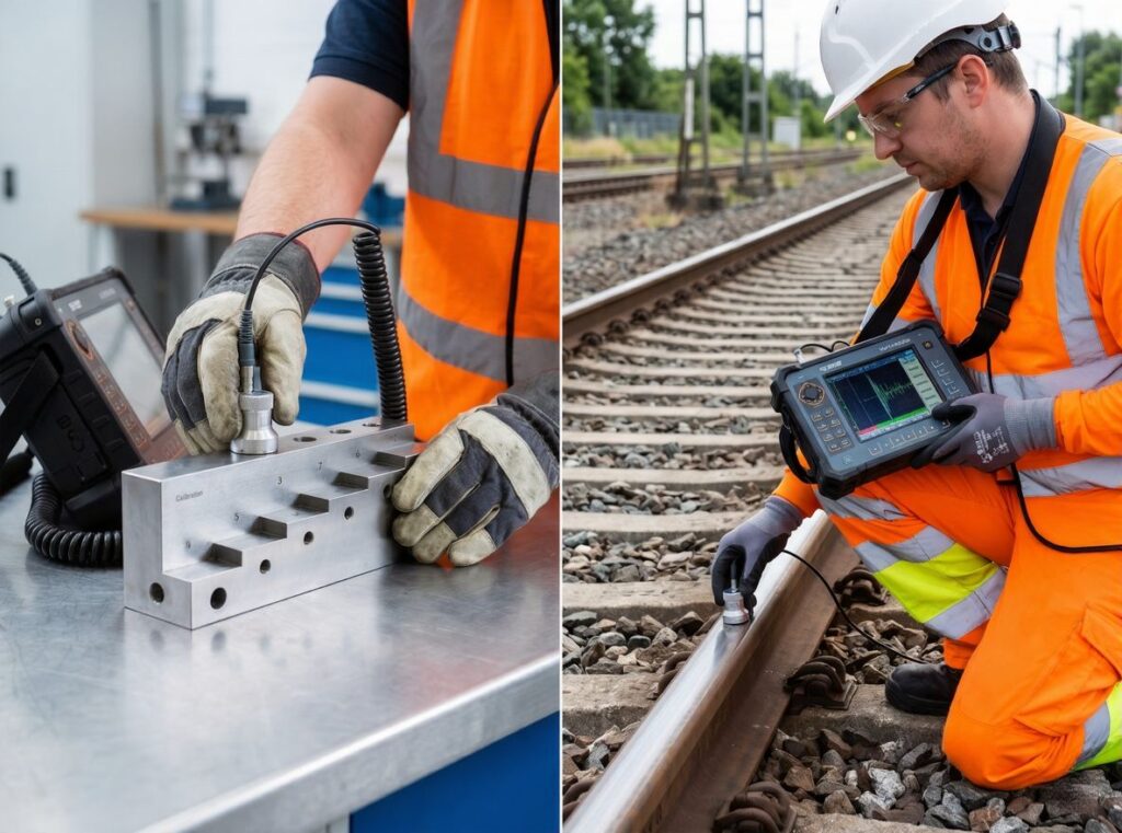
Calibration blocks serve as reference standards that help adjust ultrasonic equipment for accurate measurements. These blocks contain known reflectors and dimensions that simulate real-world defects.
In ultrasonic testing calibration, these blocks act as a benchmark. They allow technicians to verify that the equipment detects flaws correctly and measures their size and location accurately.
Without proper calibration blocks, the entire inspection process loses credibility. Even advanced systems cannot deliver reliable results if they are not standardized against known references.
What Is a Standard Block for Ultrasonic Testing?
A standard block for ultrasonic testing is a precisely manufactured reference specimen used to calibrate ultrasonic equipment. It contains artificial reflectors such as holes or notches that simulate defects.
These blocks ensure consistency and repeatability in inspection results. They also help technicians adjust sensitivity, time base, and gain settings.
Different industries use specific types of calibration blocks based on their requirements. In rail inspection, selecting the correct block is essential for accurate flaw detection.
Types of Calibration Blocks
- IIW (International Institute of Welding) Block:
Widely used for general ultrasonic testing calibration, especially in weld inspections. - AWS DSC Block:
Designed according to American Welding Society standards for sensitivity and distance calibration. - ASTM Reference Blocks:
Used in various industries, including rail inspection, for standardized testing procedures. - Railway-Specific Blocks (EN 13674 or AREMA):
Customized blocks designed specifically for rail profiles and defect simulation.
Each block type replicates specific flaw characteristics found in rails. This allows inspectors to fine-tune equipment settings before actual testing.
Using the wrong block can lead to incorrect calibration, resulting in missed defects or false indications. That is why ultrasonic testing calibration must always align with the inspection standard being followed.
Step-by-Step Ultrasonic Testing Calibration Procedure for Rails
A systematic procedure ensures that ultrasonic inspection delivers accurate and repeatable results. Ultrasonic testing calibration forms the backbone of this process.
Without a proper procedure, even skilled technicians may struggle to maintain consistency in results. Rail inspection demands precision at every stage.
What Is the Ultrasonic Testing Procedure?
The ultrasonic testing procedure is a structured process that begins with equipment setup and ends with defect evaluation and documentation.
Core Procedure Steps
- Equipment Selection and Pre-Check
Inspectors verify that the ultrasonic device functions correctly before use. - Transducer Selection (Frequency and Angle)
The choice depends on rail thickness and defect type. - Coupling Medium Application
A couplant ensures proper transmission of ultrasonic waves into the rail. - Calibration Block Setup and Gain Adjustment
Technicians adjust sensitivity using reference blocks. - Signal Amplitude and Time-Base Calibration
Ensures accurate depth and size measurements. - Scanning the Rail Surface
The transducer moves along the rail to detect flaws. - Flaw Evaluation and Recording
Data is analyzed and documented for further action.
Each step contributes to maintaining inspection accuracy. For example, improper couplant application can weaken signal transmission, while incorrect gain settings can distort readings.
Ultrasonic testing calibration plays a critical role during setup and signal adjustment stages. It ensures that the system responds accurately to known reflectors before actual inspection begins.
Rail inspection environments often present challenges such as temperature variations and surface irregularities. These factors can affect signal behavior, making calibration even more essential.
Key Standards Governing Rail Ultrasonic Testing Calibration
International standards define how ultrasonic testing calibration should be performed in rail inspection. These standards ensure consistency, reliability, and safety across different regions.
Organizations such as ASTM, ISO, and AREMA establish guidelines for equipment setup, calibration methods, and inspection procedures. These standards help maintain uniformity in testing practices worldwide.
Major Standards Comparison
| Standard | Region | Application |
| EN 13674-1 | Europe | Rail manufacturing and inspection |
| AREMA | North America | Railway engineering guidelines |
| ASTM E114 | USA | Pulse-echo ultrasonic testing |
| ISO 17640 | International | Weld inspection in steel |
| BS 9664 | UK | Ultrasonic testing of welds |
Each standard defines specific requirements for calibration blocks, testing procedures, and acceptance criteria.
EMA Quality Industries aligns its services with these globally recognized standards. This ensures that every inspection meets regulatory and safety requirements.
Failure to comply with these standards can lead to severe consequences. These include undetected rail defects, operational disruptions, and regulatory penalties.
Ultrasonic testing calibration must always follow the relevant standard to ensure accurate results. This alignment guarantees that inspections remain reliable regardless of location or application.
Why Ultrasonic Testing Calibration Accuracy Determines Rail Safety
Rail safety depends heavily on the accuracy of inspection results. Ultrasonic testing calibration directly influences this accuracy.
Even minor calibration errors can lead to serious consequences in railway operations. The reliability of defect detection depends on how well the equipment is calibrated.
Consequences of Poor Calibration
- False Negatives
Undetected cracks can grow over time and lead to derailments. - False Positives
Incorrect indications can cause unnecessary track closures and delays. - Equipment Drift
Uncalibrated systems may produce inconsistent readings. - Liability Risks
Operators may face legal and financial consequences due to inaccurate inspections.
Industry data suggests that a significant percentage of inspection failures link back to improper calibration practices. This highlights the critical role of ultrasonic testing calibration in ensuring safety.
Experts in non-destructive testing emphasize that “accurate calibration is the foundation of reliable inspection results.” This statement reflects the importance of maintaining strict calibration protocols.
Ultrasonic testing calibration ensures that every detected signal represents a real condition within the rail. It eliminates uncertainty and builds confidence in inspection outcomes.
Minimum Thickness Requirements in Ultrasonic Testing Calibration
Rail geometry is complex, with varying thickness across the head, web, and foot. Each section interacts differently with ultrasonic waves. Ultrasonic testing calibration must consider these variations to ensure accurate signal interpretation.
What Is the Minimum Thickness for UT?
The minimum thickness for ultrasonic testing is typically around 6 mm for standard contact testing, although this value depends on material properties and inspection conditions.
Thin materials create limitations for ultrasonic wave propagation. When thickness falls below a certain level, the returning signal may overlap with the initial pulse. This creates what experts call a “dead zone,” where defects remain undetected.
Factors Affecting Minimum Thickness
- Transducer Frequency
Higher frequencies improve resolution but reduce penetration depth. - Material Composition
Steel rails conduct ultrasonic waves efficiently, but alloy variations can alter wave behavior. - Near-Surface Dead Zone
This region prevents detection of very shallow defects. - Couplant Efficiency
Proper coupling ensures effective transmission of ultrasonic waves into the material.
In rail inspection, thin sections such as the web and flange demand careful attention. These areas often experience stress and fatigue, making them vulnerable to cracks.
Ultrasonic testing calibration must adjust sensitivity and time-base settings to compensate for these challenges. Without such adjustments, critical defects may remain undetected.
However, thickness alone does not determine inspection success. The equipment used plays an equally important role.
Choosing the Right Equipment for Ultrasonic Testing Calibration
Selecting the correct equipment is essential for achieving reliable inspection results. Ultrasonic testing calibration must align with the capabilities of the chosen instruments.
Modern rail inspection uses a combination of conventional ultrasonic testing and advanced phased array systems. Each method has its advantages and limitations.
Transducer Frequency and Its Effect on Calibration Accuracy
Transducer frequency directly impacts how ultrasonic waves behave inside the material. It determines both resolution and penetration depth.
Lower frequencies travel deeper into the rail but may miss small defects. Higher frequencies detect fine cracks but struggle with thicker sections.
Common Frequency Ranges in Rail UT
- 1–2.25 MHz
Used for deep penetration in thick rail heads. - 4–5 MHz
Suitable for detecting surface and near-surface flaws. - 10 MHz and Above
Ideal for thin sections and detailed inspections.
Phased array ultrasonic testing introduces additional complexity. It allows multiple beam angles and dynamic focusing, improving coverage and detection accuracy. However, it also requires more sophisticated ultrasonic testing calibration.
Conventional ultrasonic testing remains widely used due to its simplicity and reliability. It provides consistent results when calibrated correctly.
EMA Quality Industries evaluates project requirements before selecting equipment. This ensures that ultrasonic testing calibration matches inspection objectives and environmental conditions.
How Often Should Ultrasonic Testing Calibration Be Performed?
Calibration is a continuous process, not a one-time activity. Ultrasonic testing calibration must be repeated regularly to maintain accuracy throughout inspection operations.
Rail environments expose equipment to vibrations, temperature changes, and physical stress. These factors can gradually affect instrument performance.
Calibration Intervals and Triggers
- Before Each Inspection Session
Ensures the system starts with correct baseline settings. - After Equipment Impact or Shock
Physical damage can alter internal components. - After Transducer Replacement
Each probe behaves differently and requires recalibration. - Every 4–8 Hours of Continuous Use
Standard practice recommended by ASTM guidelines. - After Environmental Changes
Temperature and humidity can influence signal velocity.
Regular calibration prevents equipment drift. Drift occurs when measurements gradually deviate from actual values.
Ultrasonic testing calibration helps detect these deviations early and correct them before they affect inspection results.
Documentation is equally important. Calibration records provide traceability and support compliance with regulatory requirements. They also help identify patterns in equipment performance over time.
Skipping recalibration increases the risk of inaccurate readings. This can lead to undetected defects or unnecessary maintenance actions.
EMA Quality Industries’ Approach to Rail Ultrasonic Testing Calibration
EMA Quality Industries adopts a structured and disciplined approach to rail inspection. Ultrasonic testing calibration remains central to this methodology.
The company employs certified technicians trained in international standards such as ASTM, ISO, and EN. These professionals follow strict calibration protocols to ensure consistent results.
EMA provides a wide range of services, including rail weld inspection, track condition assessment, and maintenance support. Each service relies on accurate calibration practices.
One of the key strengths of EMA lies in its commitment to traceability. Every calibration activity is documented, creating a reliable record for audits and compliance checks.
This approach reduces uncertainty and enhances confidence in inspection outcomes. It also ensures that railway operators meet regulatory requirements without compromise.
Ultrasonic testing calibration at EMA focuses on precision, consistency, and reliability. These qualities contribute directly to safer rail operations.
Common Mistakes in Ultrasonic Testing Calibration and How to Avoid Them
Even experienced technicians can encounter challenges during calibration. Small mistakes can have significant consequences in rail inspection. Ultrasonic testing calibration must be performed with precision and attention to detail.
Top Calibration Errors
- Using Worn or Damaged Calibration Blocks
Damaged blocks produce inaccurate reference signals, leading to incorrect calibration. - Improper Couplant Application
Insufficient or uneven couplant reduces signal transmission efficiency. - Ignoring Temperature Variations
Temperature changes affect material properties and wave velocity. - Skipping Sensitivity Checks
Failure to verify sensitivity can result in missed defects. - Misinterpreting Reference Signals
Incorrect identification of reflectors affects calibration accuracy.
Each of these errors can compromise inspection reliability. Proper training and adherence to standards help minimize these risks.
Regular audits and equipment maintenance also play a crucial role in preventing calibration issues.
Ultrasonic testing calibration requires a disciplined approach. Consistency in procedures ensures accurate and repeatable results.
Final Thoughts
Railway safety depends on precise inspection methods that ensure hidden defects are identified before they become critical. Ultrasonic testing calibration plays a central role in achieving this level of accuracy by ensuring that every signal reflects the true condition of the rail.
Accurate calibration supports reliable detection, minimizes false readings, and strengthens confidence in inspection results. It also ensures compliance with international standards, which is essential for maintaining consistent safety practices across rail networks.
Ultrasonic testing calibration remains essential for maintaining equipment performance under varying environmental and operational conditions. When performed correctly and consistently, ultrasonic testing calibration helps prevent failures, reduces maintenance costs, and enhances the overall reliability of railway infrastructure.
Key Takeaways
- Ultrasonic testing calibration ensures accurate detection of internal rail defects before failures occur
- Proper calibration blocks help standardize inspection results across different railway systems globally
- Following structured ultrasonic testing procedures improves consistency and reduces inspection errors significantly
- Minimum thickness considerations directly affect ultrasonic wave behavior and flaw detection capability
- Selecting the correct transducer frequency balances penetration depth and defect detection resolution
- Regular ultrasonic testing calibration prevents equipment drift and maintains consistent inspection accuracy
- Compliance with international standards ensures reliable inspection practices and regulatory acceptance
- Environmental factors such as temperature and surface conditions influence calibration effectiveness greatly
- Avoiding common calibration mistakes improves inspection reliability and reduces operational risks
- Expert calibration practices enhance railway safety and extend the service life of tracks
FAQs
How is ultrasonic testing calibrated?
Ultrasonic testing is calibrated using reference calibration blocks that contain known reflectors. Technicians adjust gain, sensitivity, and time-base settings so the equipment accurately detects and measures flaws. This process ensures that signals correspond correctly to defect size and location.
What is a calibration block in ultrasonic testing?
A calibration block is a precisely manufactured reference specimen with artificial defects such as holes or notches. It is used to standardize ultrasonic equipment settings and verify accuracy before actual inspection begins.
What is the ASME standard for UT test?
The ASME standard for ultrasonic testing is primarily covered under ASME Section V. It provides guidelines for equipment setup, calibration procedures, and inspection methods used in non-destructive testing.
What is the frequency of ultrasonic inspection?
Ultrasonic inspection frequency depends on operational conditions, but calibration is typically performed before each inspection session and periodically during use, often every 4 to 8 hours, or after environmental changes.
Does temperature affect ultrasonic testing?
Yes, temperature significantly affects ultrasonic testing. Changes in temperature alter sound velocity in materials, which can impact measurement accuracy. Proper calibration adjustments are necessary to maintain reliable results under varying conditions.