

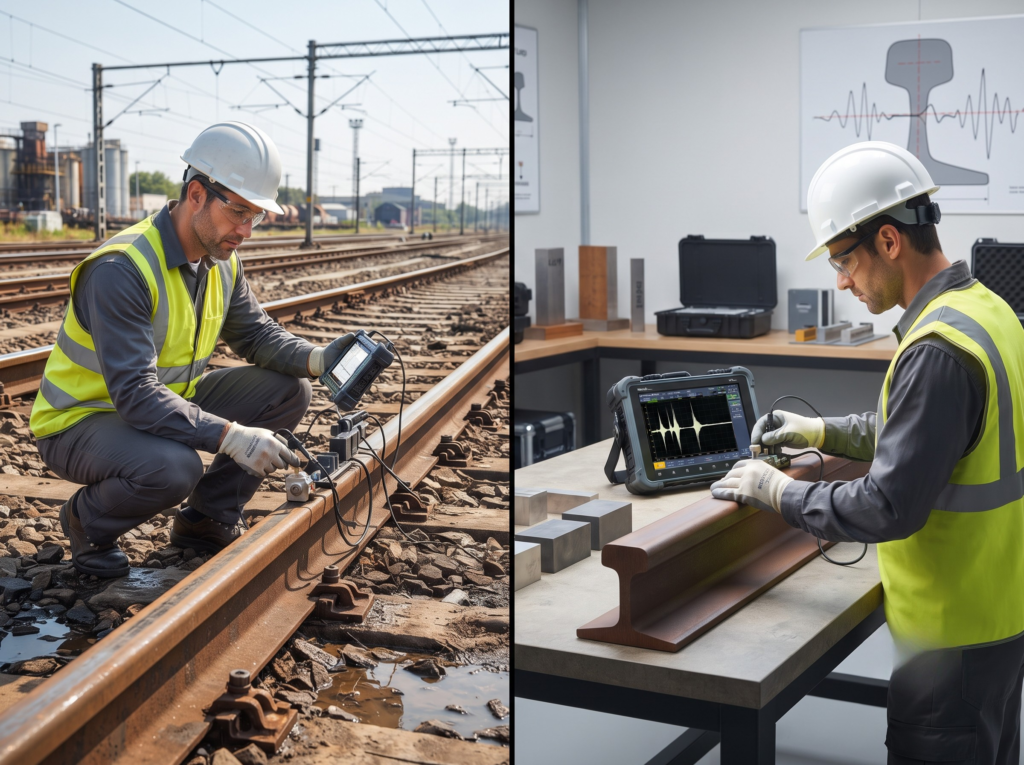
A signal appears on an ultrasonic rail inspection system, but does it always mean there is a defect in the rail? Not necessarily. False calls in rail UT can occur when a response comes from rail geometry, an uneven surface, poor coupling, equipment noise, or another source rather than an actual flaw.
That can make rail inspection more complicated than simply finding a signal and marking its location. Ultrasonic testing is widely used to look for internal rail defects that cannot be seen during a visual inspection. At the same time, the ultrasonic beam can interact with different parts of the rail as it travels through the material. Some of those responses are expected, while others need closer investigation.
This is where false calls in Rail UT become a practical concern. A genuine ultrasonic indication still needs to be interpreted before it can be classified as a defect. If a normal reflection is mistaken for a flaw, the result can be an unnecessary inspection or maintenance response. If the inspection becomes less sensitive just to avoid such calls, however, a genuine defect could be missed.
What Is a False Call in Rail Ultrasonic Testing?
False Calls in Rail UT occur when an inspection response is interpreted as a relevant rail defect even though the response comes from another source. The source may be a normal geometric feature, surface condition, coupling variation, equipment response, or another acoustic phenomenon.
The difference between an indication and a confirmed defect sits at the heart of the issue. Ultrasonic equipment sends high-frequency sound into the rail and receives reflected energy. When the sound encounters a discontinuity, part of the energy can return to the transducer and appear on the inspection display. However, other interfaces and geometric features can also reflect ultrasonic energy.
A useful way to understand the possible outcomes is through four basic inspection results of false calls in Rail UT:
| Inspection result | Actual rail condition | Inspection outcome |
| True positive | Relevant defect exists | Defect is detected |
| False positive | No relevant defect exists | Defect is reported |
| True negative | No relevant defect exists | No defect is reported |
| False negative | Relevant defect exists | Defect is missed |
False calls in Rail UT represent the false-positive side of this equation. Although they may appear less serious than missed defects, repeated false positives can consume inspection and maintenance resources, trigger unnecessary investigations, and reduce confidence in inspection results.
Sonatest’s discussion of ultrasonic inspection illustrates the wider problem. In an HSE case study involving 40 certified ultrasonic operators inspecting complex weld geometries, the operators produced 16 reported false calls. Sonatest explains that the difficulty involved distinguishing geometrical indications from genuine flaws. The example concerns weld inspection rather than railway rails, but it demonstrates an important UT principle: a real ultrasonic response does not automatically identify a real defect.
Main Causes of False Calls in Rail UT
Rail Geometry and Legitimate Reflectors
Rail geometry represents one of the fundamental sources of misleading ultrasonic responses. The sound beam can encounter boundaries and changes in shape that naturally reflect acoustic energy.
The rail head, web and base do not present identical inspection conditions. The shape of the rail can alter beam paths and create reflections that have nothing to do with material damage.
A recent review of rail NDT methods highlights the complexity of ultrasonic inspection and the limitations of conventional probe arrangements. It also describes research into phased-array, EMAT and laser-based ultrasonic systems developed partly to improve coverage and overcome some limitations of conventional UT.
False calls in Rail UT can occur when a legitimate geometric reflection receives the same attention as a possible defect. The signal itself may be genuine; the error lies in identifying its source.
This distinction becomes particularly important in automated inspection. Systems that record large quantities of ultrasonic information need reliable methods for separating expected responses from potentially significant abnormalities.
Poor Rail Surface Condition and Contamination
Rail surface condition can also influence ultrasonic inspection. Dirt, oil, grease, rust, scale, roughness and surface damage can interfere with the transmission of ultrasonic energy.
The rail NDT review notes that surface defects can interfere with ultrasonic rail flaw detection and can contribute to situations where internal defects become harder to detect. Conventional UT also depends on coupling, which makes the inspection interface an important part of overall performance.
A contaminated or irregular surface can change the acoustic response. The resulting signal may look unusual even when the underlying rail does not contain the suspected internal defect.
This creates a difficult situation. A poor surface condition can contribute to a false call, but it can also contribute to a missed defect. Treating surface preparation as a minor housekeeping issue therefore understates its importance.
False calls in Rail UT should always be considered alongside the condition of the surface being inspected.
Coupling Problems
Conventional contact UT generally requires effective coupling between the transducer and the rail. If that coupling becomes inconsistent, the ultrasonic response can change even though the rail itself has not changed.
Possible causes include:
- Uneven contact
- Contamination at the inspection interface
- Loss of coupling
- Mechanical movement
- Changes in operating conditions
- Environmental effects
The rail NDT review specifically identifies coupling agents as a limitation of conventional rail UT and notes that weather conditions and higher inspection speeds can interfere with coupling.
False calls in rail UT can therefore appear when an operator interprets an unstable response as evidence of a flaw rather than first checking whether the inspection conditions could explain the signal.
Coupling problems also demonstrate why a single amplitude reading should rarely determine the final interpretation. Signal behavior needs to be considered in context.
Equipment Noise and Signal-Processing Effects
Modern rail inspection systems process much larger quantities of ultrasonic data than traditional manual equipment. Electronic noise, signal variability and processing effects can influence what appears on the inspection display.
Wabtec’s rail-bound ultrasonic system, for example, uses 24-, 32- or 48-channel digital signal processing depending on the configuration. The company states that this approach supports real-time sequential processing, improved signal-to-noise ratios, higher testing speeds and fewer false-positive results.
Digital processing does not eliminate the need for interpretation. Instead, it can improve the quality of the information available for interpretation.
False calls in rail UT become more difficult to control when noise or unwanted signal variation obscures the difference between a meaningful response and an irrelevant one. Better signal processing can narrow that gap.
Acoustic Propagation Artifacts
Ultrasonic energy does not always travel through rail in a simple straight line. Rail geometry can influence propagation, reflections and the interaction of different wave modes.
Research into rail ultrasonic inspection has examined complex wave behavior and artifacts that can interfere with interpretation. Such effects help explain why some responses may repeat in predictable locations without representing material damage.
False calls in rail UT can therefore originate from acoustic behavior that is physically real but diagnostically misleading.
The important point is that the source of an indication must be established before the indication becomes a defect classification.
Types of False Calls in Rail UT
False calls in rail UT can be grouped according to the source of the misleading response. The categories can overlap because a single indication may involve more than one contributing factor.
- Geometrical false indications
Reflections originate from normal rail geometry rather than a material discontinuity. - Surface-condition indications
Contamination, roughness, rust or surface damage affects the ultrasonic response. - Coupling-related indications
Changes in acoustic coupling alter the signal and create an appearance that can be mistaken for a defect. - Equipment and electronic indications
Noise, channel variation or processing effects produce responses that require investigation. - Acoustic propagation artifacts
Complex wave paths, reflections and other propagation effects create repeatable but misleading signals. - Interpretation-based false calls
The ultrasonic response is genuine, but the inspector incorrectly identifies its source or significance.
This classification shows why false calls in rail UTfalse calls in Rail UT cannot be reduced to one single technical problem. Some arise from the rail itself, some from the inspection conditions, and others from the interaction between the equipment and the person interpreting the data.
How Modern Rail UT Technology Helps Reduce False Positives
Modern rail flaw detection systems combine ultrasonic acquisition with digital processing, automated analysis and location tracking. These developments can reduce some of the conditions that contribute to false calls in rail UT.
Multi-Channel Digital Signal Processing
Wabtec’s rail-bound ultrasonic system uses 24-, 32- or 48-channel digital signal processing depending on configuration. The company states that the system supports improved signal-to-noise performance, continuous inspection and reduced false-positive results.
Multiple channels allow the system to collect more information from the rail during an inspection pass. This can make it easier to compare responses from different inspection paths rather than relying on a single isolated signal.
Digital processing does not make every indication reliable automatically. Its value comes from improving the quality and consistency of the information available for analysis.
Pattern Recognition and Automated Classification
Pattern recognition can help identify signal characteristics associated with known rail defects and recurring non-defect responses. Wabtec incorporates pattern recognition and defect classification into its automated rail flaw detection approach.
Automation becomes particularly useful when an inspection vehicle generates large volumes of data. Software can identify unusual responses and direct attention toward locations that require further examination.
This approach can help control false calls in rail UT, but automated classification still requires appropriate validation. An unfamiliar signal should not automatically be treated as either a defect or a harmless indication simply because software has categorized it.
Better Visualization and Defect Location
Visualization can improve interpretation by showing more than signal amplitude alone. Sonatest’s inspection software uses interactive scan planning and real-time ray tracing to represent expected ultrasonic beam paths. That information can help distinguish geometrical reflections from possible defects.
Rail-bound systems can also connect detected indications with their physical location. Wabtec describes GPS and chainage-based defect location, allowing inspection results to be linked to specific points on the track.
Accurate location makes follow-up inspection easier. A questionable indication can be returned to, examined again and compared with the original inspection record.
Combining UT With Other NDT Methods
UT cannot provide complete coverage of every possible rail condition. The rail NDT review describes ultrasonic, electromagnetic and visual inspection as complementary technologies. UT has particular value for internal defects, while other methods can provide additional information about surface and subsurface conditions.
This means that reducing false calls in rail UT does not always require making UT perform every task. Combining complementary inspection methods can provide additional evidence when a single technique has limitations.
Practical Rail UT False-Call Reduction Workflow
A structured process can reduce false calls in rail UT before an indication becomes a final defect classification:
- Record the indication and its location.
- Check equipment condition and calibration.
- Verify surface and coupling conditions.
- Determine the apparent reflector location.
- Compare the response with expected rail geometry and beam paths.
- Assess the signal according to the applicable inspection procedure.
- Perform additional verification when required.
- Classify and document the result.
- Use confirmed indications as future training and validation examples.
This approach creates a clear separation between detecting an indication and deciding what that indication means.
Final Thoughts
False calls in rail UT can originate from rail geometry, surface condition, coupling, equipment behavior, acoustic propagation and human factors. Treating the issue as a single operator problem overlooks the way these factors interact during real inspections.
Better surface preparation, reliable coupling, accurate calibration and inspection-specific procedures can reduce avoidable indications. Training and independent verification can strengthen human decision-making, while digital signal processing, pattern recognition, improved visualization and accurate location tracking can provide additional technical support.
The goal is not simply to eliminate false calls in rail UT. An inspection system that reports fewer indications by becoming less sensitive could increase the risk of missed defects. The stronger objective is a validated inspection process that detects relevant rail flaws reliably while keeping unnecessary alarms under control.
Key Takeaways
- False calls can originate from rail geometry, surface conditions, coupling, equipment, and acoustic behavior.
- An ultrasonic indication does not automatically confirm the presence of a relevant rail defect.
- Poor rail surface conditions can interfere with ultrasonic transmission and create misleading inspection responses.
- Consistent coupling helps maintain stable ultrasonic signals and reduces unnecessary signal variations during inspection.
- Proper calibration and inspection-specific procedures provide important controls for reliable ultrasonic rail testing.
- Operator training should include genuine defects alongside common geometrical, coupling, and equipment-related indications.
- Digital signal processing can improve signal quality and help reduce unnecessary false-positive inspection results.
- Pattern recognition and automated classification can support inspectors when large volumes of rail inspection data require analysis.
- Probability of Detection and false-alarm performance provide valuable measures of overall rail inspection reliability.
- The goal is not eliminating every false call, but detecting genuine defects while controlling unnecessary alarms.
FAQs
What are the types of defects in rails?
Yes. Common rail defects include transverse defects, longitudinal defects, horizontal split heads, vertical split heads, detail fractures, engine burns, and bolt-hole cracks. False calls in rail UT can sometimes make it difficult to distinguish these genuine defects from normal rail reflections or other non-defect indications. Ultrasonic testing is particularly useful for identifying internal flaws that visual inspection may not reveal.
What are common defects found by ultrasonics?
Yes. Ultrasonic testing can identify internal discontinuities such as cracks, inclusions, laminations and other flaws, depending on the inspection setup. In rail applications, False calls in rail UT can occur when non-defect reflections resemble genuine flaws. Probe angle, frequency, coupling and scanning conditions all influence how effectively ultrasonic inspection identifies relevant internal defects.
What are the different types of UT scan?
Yes. Common UT scanning approaches include straight-beam, angle-beam, raster, linear and encoded scanning. Phased-array scanning can also steer and focus ultrasonic beams electronically using multiple elements. Choosing the right scan helps limit false calls in rail UT because the beam path, inspection coverage and expected defect orientation can be matched more closely to the rail’s geometry and inspection requirements.
What is the difference between UT and PAUT testing?
Yes. Conventional UT generally uses a single-element or limited-element probe, while PAUT uses multiple elements that can electronically steer and focus ultrasonic beams. PAUT can provide wider coverage and more detailed information from different angles. This additional control can help reduce false calls in rail UT when complex rail geometry makes conventional ultrasonic responses difficult to interpret.
