

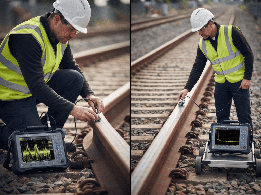
In ultrasonic testing, Near Field vs Far Field in UT describes two distinct regions of the sound field produced by a transducer.
Near Field vs Far Field in UT also affects probe selection, near-field calculations, focusing, and the interpretation of amplitude-based indications.
What Are the Near Field and Far Field in Ultrasonic Testing?
The sound beam from a conventional ultrasonic transducer does not behave like a perfectly uniform column of energy. A piezoelectric element generates mechanical vibrations when an electrical pulse excites it, and those vibrations travel into the test material as ultrasonic waves. The beam contains pressure variations in both axial and transverse directions.
The Near Field
The near field, often called the Fresnel zone, is central to Near Field vs Far Field in UT and lies directly in front of the transducer. Sound pressure passes through a series of maxima and minima in this region. Waves emitted from different parts of the active element interfere with one another, creating a complicated pressure pattern rather than a smoothly decreasing signal.
For an unfocused circular transducer, the near field ends at the last major on-axis pressure maximum. That point is commonly identified as the near-field distance, or natural focus. Evident notes that pressure variations within this region can make amplitude-based flaw evaluation difficult.
The Far Field
The far field begins beyond the near-field distance. Here, the beam spreads progressively while sound pressure decreases in a more predictable manner.
Near Field vs Far Field in UT becomes especially important when an indication lies close to the boundary between these regions. The same reflector can produce a different response depending on where it sits within the sound field.
Why Does the Near Field Form?
A conventional single-element transducer behaves approximately like a piston source. When the piezoelectric element receives an electrical pulse, it deforms and springs back, producing a short mechanical pulse.
Those wavefronts interact as they move through the material. Where wave contributions reinforce one another, pressure increases. Where they cancel, pressure decreases. This constructive and destructive interference creates the alternating maxima and minima that characterize the near field.
The next practical question in Near Field vs Far Field in UT is straightforward: how can the approximate end of this complicated region be determined for a particular probe?
How Is Near-Field Length Calculated in UT?
For a conventional circular transducer, the approximate near-field length can be calculated from:
[N = \frac{D^2}{4\lambda}]
The wavelength is:
[\lambda = \frac{v}{f}]
Therefore:
[N = \frac{D^2f}{4v}]
Where:
| Symbol | Meaning |
| N | Near-field length |
| D | Transducer diameter |
| λ | Wavelength |
| v | Sound velocity in the test material |
| f | Transducer frequency |
The near-field length increases as active diameter increases and also increases with frequency when other variables remain constant. Published ultrasonic research uses the same approximate relationship and connects near-field length with transducer diameter, wavelength, material velocity, and frequency.
How Transducer Diameter Changes Near-Field Length
Diameter has a strong influence because it appears as a squared term. Doubling the diameter while keeping frequency and material velocity unchanged increases the calculated near-field length by approximately four times.
Near Field vs Far Field in UT is partly a probe-selection issue for this reason. A larger active element can extend the region in which pressure fluctuations influence signal interpretation.
How Frequency Changes Near-Field Length
As frequency rises, wavelength becomes shorter. With diameter and material velocity held constant, the calculated near-field length therefore increases.
Frequency also affects other inspection characteristics. Evident notes that lower frequencies generally provide greater penetration, while higher frequencies provide better resolution and focal sharpness.
How Sound Velocity Changes Near-Field Length
Material sound velocity affects wavelength. A higher velocity produces a longer wavelength at the same frequency and reduces the calculated near-field length. A lower velocity produces a shorter wavelength and increases the calculated length.
Near Field vs Far Field in UT does not mean the probe suddenly changes behavior at exactly 85 mm. The result represents an engineering approximation of the distance to the last major on-axis pressure maximum. Practical beam response can also depend on probe construction, damping, focusing, and material properties.
For rectangular or square elements, the circular-diameter relationship should not be applied blindly. Evident provides geometry-dependent considerations for rectangular and square apertures, including an aspect-ratio constant.
Why Near-Field Effects Matter During UT Inspection
The important inspection issue is knowing what can happen when a reflector lies inside the near-field region. Near Field vs Far Field in UT directly affects the reliability of amplitude-based interpretation.
Sound pressure changes from one location to another within the near field. Consequently, an indication can change in amplitude as probe or reflector position changes, even when the reflector itself remains essentially the same. Evident identifies these pressure variations as a reason accurate flaw evaluation can become challenging.
Technical NDT training material also notes greater interpretation difficulty for smaller defects in the near zone.
Why Echo Amplitude Can Be Misleading
An ultrasonic display shows the response received by the transducer, not a direct image of the reflector. Received amplitude depends on reflector orientation, distance, attenuation, coupling, probe characteristics, and local sound pressure.
| Inspection factor | Near Field | Far Field |
| Pressure pattern | Complex maxima and minima | More predictable decrease |
| Beam behavior | Strong interference effects | Progressive divergence |
| Echo amplitude | Can fluctuate significantly | Generally more systematic |
| Flaw evaluation | Requires greater care | Usually easier to interpret |
| Main concern | Sound-field variation | Attenuation and beam spread |
The far field offers more predictable beam behavior, but attenuation and beam spread remain. Near Field vs Far Field in UT should therefore never be treated as a simple “bad zone versus good zone” distinction.
How Transducer Characteristics Affect the Sound Field
The sound field begins with the transducer, so Near Field vs Far Field in UT also depends on probe characteristics. Conventional NDT transducers are commonly selected according to type, active diameter, frequency, bandwidth, waveform duration, and sensitivity. Material condition, accessibility, defect position, and inspection speed also influence selection.
Why Probe Selection Changes Near-Field Behavior
A larger aperture generally produces a longer near field. A higher frequency generally produces a longer near field for the same aperture and material velocity. A change in material also changes wavelength and the calculated near-field distance.
Probe geometry matters as well. Circular elements use diameter in the conventional relationship, while rectangular and square elements require their dimensions and aspect ratio to be considered.
Focusing also changes beam behavior. Evident notes that the near-field distance represents the greatest distance at which a transducer can be focused using an acoustic lens or phasing techniques.
What Happens When the Beam Enters the Far Field?
Once the beam passes the near-field region, pressure behavior becomes more predictable and the beam begins to diverge. The sound field gradually decreases in strength as the beam diameter expands and energy spreads through a larger volume.
This makes Near Field vs Far Field in UT easier to understand from an inspection perspective: the near field is dominated by complex interference, while the far field is dominated by beam divergence and progressive energy loss.
Near Field vs Far Field in UT does not create a sharp physical boundary visible on the component. It represents a change in the dominant behavior of the sound field. Near Field vs Far Field in UT therefore becomes most useful when the calculated boundary is compared with the actual inspection volume. Near Field vs Far Field in UT guides signal interpretation.
The physics is clear. Near Field vs Far Field in UT guides signal interpretation. But the practical question remains: what should an inspector do when a reflector sits inside that complicated zone? That is where probe selection, inspection technique, and signal interpretation become critical.
How Should Inspectors Handle Near-Field Indications?
When a reflector falls inside the near field, the inspection does not automatically become invalid. Instead, Near Field vs Far Field in UT becomes a practical consideration during signal interpretation. The inspector needs to understand where the reflector sits in relation to the probe’s sound field and then apply the inspection procedure correctly.
A practical sequence can help:
- Identify the transducer diameter, frequency, and element geometry.
- Establish the appropriate sound velocity for the test material.
- Calculate or obtain the approximate near-field length.
- Compare the reflector location with the calculated near-field region.
- Consider whether signal changes could result from the sound-field pattern rather than a change in the reflector.
- Apply the relevant calibration, evaluation, and acceptance requirements from the inspection procedure.
Near Field vs Far Field in UT should therefore form part of the inspector’s interpretation process rather than serve as a reason to reject an indication automatically.
A near-field indication deserves careful evaluation because pressure can vary considerably over a relatively short distance. Probe movement, reflector position, surface condition, coupling, and reflector orientation can all influence the received signal. The inspection procedure remains the final authority for determining how an indication should be evaluated.
Can Near-Field Effects Be Reduced?
Several inspection approaches can reduce the practical problems associated with the near field. The appropriate method depends on component geometry, inspection depth, defect characteristics, probe type, and the applicable procedure.
A delay-line probe can place a material delay between the active element and the test surface. This arrangement can move the inspection region away from the most complicated portion of the sound field. IAEA training material identifies the use of a plastic shoe in front of the crystal as one way of reducing or overcoming near-field difficulties.
Focused probes provide another approach. An acoustic lens can concentrate the beam at a selected depth, while phased-array systems can use controlled timing between elements to steer and focus the beam. These techniques do not eliminate Near Field vs Far Field in UT; they give greater control over how the acoustic energy interacts with the inspection volume.
Probe selection also plays an important role. Frequency, aperture, element geometry, and material velocity all influence the sound field. Evident notes that frequency selection involves a balance between penetration and resolution, while transducer dimensions influence the beam profile and near-field distance.
The goal is not always to eliminate the near field. In many inspections, the more realistic goal is to understand its position and behavior well enough to interpret indications correctly.
What Is Near Zone and Far Zone in Ultrasound?
In ultrasound terminology, the near zone commonly refers to the near field, also known as the Fresnel zone. The far zone commonly refers to the far field, or Fraunhofer zone.
Near Field vs Far Field in UT can therefore be expressed using either pair of terms. The near zone contains complex interference patterns, while the far zone shows progressive beam divergence and a more predictable decrease in sound pressure.
The boundary between the two depends on factors such as transducer aperture, wavelength, frequency, and sound velocity. For a conventional circular transducer, the approximate relationship remains:
[N = \ frac {D^2} {4 \ lambda} ]
The formula provides an engineering estimate rather than a perfectly sharp physical dividing line.
Final Thoughts
A sound field influences every ultrasonic inspection, even when its effects remain invisible on the instrument display. Near Field vs Far Field in UT helps explain why a reflector can produce changing amplitudes in one region and more predictable responses in another.
The near field contains complex pressure variations, while the far field produces progressive beam divergence and more systematic pressure reduction. Transducer diameter, frequency, wavelength, material velocity, and element geometry all contribute to this behavior.
Near Field vs Far Field in UT should never replace an approved inspection procedure, calibration method, or acceptance criterion. Instead, it provides the technical foundation needed to understand the signals produced during an inspection.
For inspectors, the key lesson is simple: knowing where the inspection target sits within the sound field can make signal interpretation more informed, more consistent, and technically defensible.
Key Points
- Near Field vs Far Field in UT explains how ultrasonic energy behaves at different distances.
- The near field contains pressure variations that can complicate amplitude-based flaw evaluation.
- Larger transducer diameters generally produce longer near-field distances under similar inspection conditions.
- Higher ultrasonic frequencies generally increase near-field length while improving resolution and focal sharpness.
- Material sound velocity affects wavelength and changes the calculated near-field distance.
- Near Field vs Far Field in UT helps explain variations in received echo amplitude.
- Inspectors should consider probe geometry before applying a standard near-field calculation.
- Far-field behavior becomes more predictable as the beam moves beyond natural focus.
- Near-field effects do not automatically make an ultrasonic inspection invalid or unreliable.
- Understanding the sound field helps inspectors interpret indications with greater technical confidence.
Frequently Asked Questions
How many types of probes are in UT?
No. There is no single fixed number of ultrasonic probes used in every inspection. Common UT probes include straight-beam, angle-beam, dual-element, delay-line, immersion, focused, and phased-array probes. Probe selection depends on material, thickness, defect location, geometry, and inspection objectives. Near Field vs Far Field in UT also influences how a probe’s characteristics affect beam behavior and signal interpretation.
How to calculate far field?
Yes. The far-field boundary for a conventional circular ultrasonic transducer can be estimated using the near-field relationship, where the far field begins beyond the approximate near-field length. A commonly used relationship is N = D²/(4λ), with wavelength calculated from λ = v/f. Near Field vs Far Field in UT depends on aperture, wavelength, frequency, and material sound velocity.
What is meant by near-field?
Yes. The near field is the region immediately in front of an ultrasonic transducer where sound pressure varies through maxima and minima caused by wave interference. It is also called the Fresnel zone. Near Field vs Far Field in UT is important because these pressure variations can make echo amplitudes difficult to interpret, particularly during conventional amplitude-based flaw evaluation.
What is meant by far field?
Yes. The far field is the region beyond the near-field distance where the ultrasonic beam progressively diverges and sound pressure decreases in a more predictable manner. It is also called the Fraunhofer zone. Near Field vs Far Field in UT helps distinguish the complex interference behavior near the probe from the more systematic beam behavior farther from the transducer.
What is the farfield distance?
Yes. The far-field region begins beyond the approximate near-field distance of the transducer, although it does not have a perfectly sharp physical boundary. For a conventional circular element, the near-field distance can be estimated using N = D²/(4λ). Near Field vs Far Field in UT therefore requires consideration of transducer diameter, wavelength, frequency, and material sound velocity.
Meta description
Learn how Near Field vs Far Field in UT affects ultrasonic beam behavior, echo amplitude, probe selection, near-field calculations, and defect interpretation.
