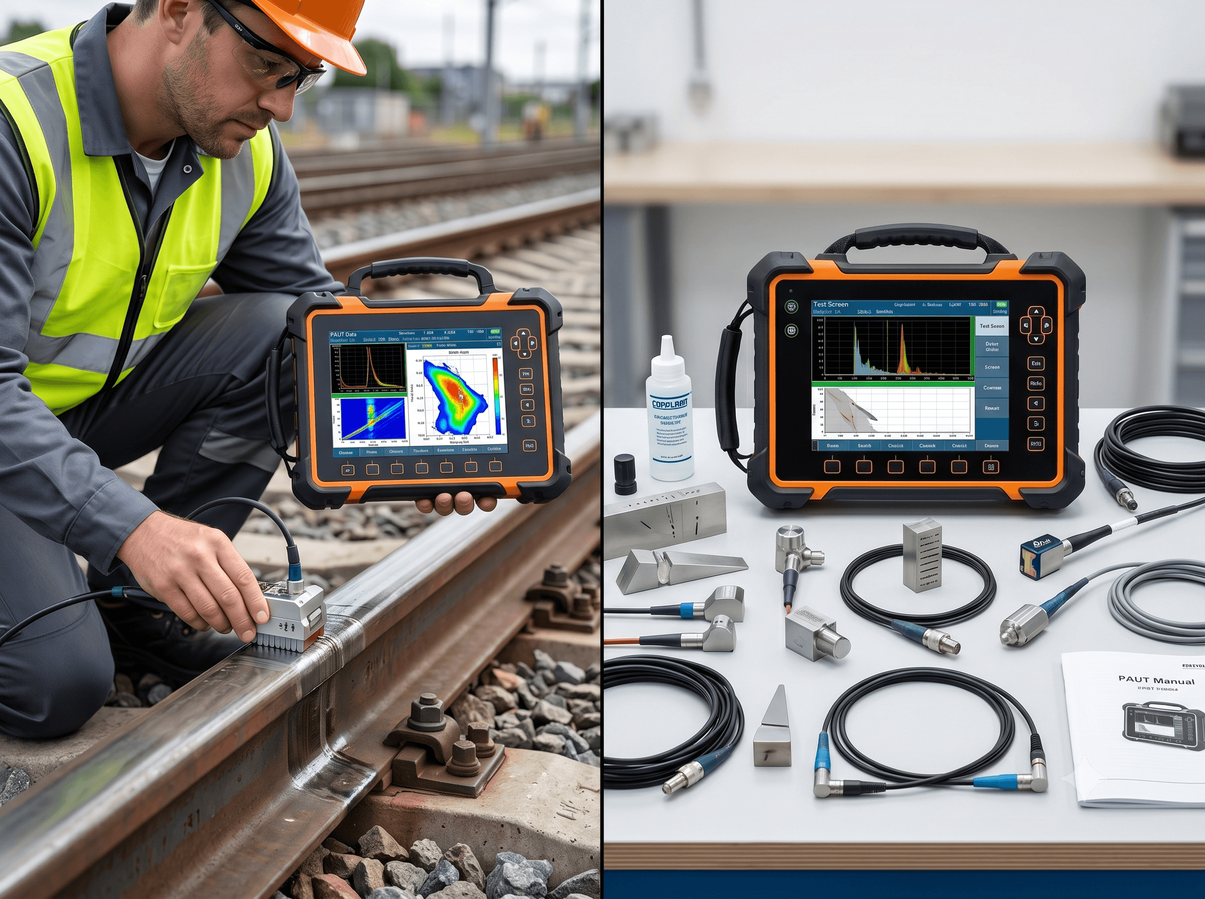
Phased array ultrasonic testing equipment is the instrument, array probe, wedge, encoder and software a contractor uses to scan a weld with electronically steered beams. For code work a buyer should specify the channel count, focal laws, probe pitch and frequency, encoded data, and ACG/TCG calibration on named blocks; the AWS D1.1:2020 PAUT annex reportedly sets a 16-element minimum.
This guide is written for the person who buys the inspection, not the instrument: a weld QA manager, a structural engineer or a transit agency engineer writing a scope. It explains what each piece of PAUT equipment does, which numbers matter, how to check them and which codes ask for them. It also says plainly where phased array fits in rail work, and where it doesn't.
If you want the difference between conventional UT and PAUT as methods, read UT vs PAUT: what's the difference. This article starts where that one stops: the contractor has proposed PAUT, and you need to know what to ask them to bring.
What does a phased array ultrasonic testing equipment package include?
A PAUT package is five things that only work together: the instrument, the array probe, the wedge, the scanner with its encoder, and the setup and analysis software. A good probe on a poorly matched wedge, or a good instrument with no encoder, produces data that can't be checked later. Specify the package, not a brand of instrument.
| Component | What it does | What the buyer should see named in the procedure |
|---|---|---|
| Instrument (pulser/receiver) | Fires each element with a computed delay, receives and sums the echoes | Pulser and receiver count, maximum focal laws, digitizing settings, encoder inputs |
| Array probe | A row of small piezoelectric elements in one housing | Frequency, number of elements, pitch, elevation (passive aperture) |
| Wedge | Sets the incident angle and protects the probe face | Nominal angle, wedge material velocity, height to the first element, contour |
| Scanner and encoder | Holds the probe at a fixed offset and records position | Scanner type, encoder resolution, calibration distance |
| Software | Calculates focal laws, displays, stores and analyzes data | Software version, file format, export options, analysis licence |
TOFD channels are often added to the same instrument for weld work. That is a separate technique with its own probes and its own dead zones; see PAUT vs TOFD for rail weld inspection for where each one helps.
Key takeaway: a buyer specifies the whole chain, because the data are only as good as the weakest link in it.
What should a buyer specify for the PAUT instrument?
Specify how many elements the instrument can fire at once, how many focal laws it can hold, whether it records encoded position, and what file format the raw data come out in. These four numbers decide whether a scan plan is possible at all.
Pulsers, receivers and channel notation
Instruments are commonly described by two numbers, such as 16:64 or 32:128. The first is the number of elements that can be fired together in one focal law (the active aperture). The second is the number of elements the instrument can address in total, so it can step a 16-element aperture along a 64-element probe.
Evident's tutorial notes that "Most standard instruments will support apertures of up to 16 elements." A 16-element aperture is a practical floor for weld work. Larger apertures (32 elements) help on thick sections because a larger aperture pushes the focusing range deeper, as the worked example below shows.
Focal-law capacity
A focal law is one set of firing delays: one angle, one focal depth, one aperture position. An S-scan from 40° to 70° in 1° steps is 31 focal laws. An E-scan that steps a 16-element aperture one element at a time along a 64-element probe is 49 focal laws.
Two probes, one each side of a weld, double the count to 62 S-scan laws. Add TOFD channels and a second focal depth and the total climbs quickly. Ask the contractor to state the total for the scan plan and confirm the instrument can run it at the planned scan speed without dropping data.
Encoder inputs and data
Code PAUT is usually encoded: a wheel or string encoder records where the probe was for every stored A-scan. The instrument needs at least one encoder input for a one-line scan along the weld, and two for raster scans. Without encoded position, there is no C-scan or top view, and no way for a second person to re-evaluate the data.
Raw data volume matters for record keeping. In an illustrative case, 1,000 encoded positions (1 m of weld at a 1 mm step) × 62 focal laws × 1,024 samples per A-scan × 2 bytes per sample is about 127 MB for one weld, before TOFD.
| Instrument item | Typical buyer requirement | Why it matters |
|---|---|---|
| Active aperture | At least 16 elements; 32 for thick or deep-focus work | Sets sensitivity and the depth to which focusing works |
| Addressable elements | Matches the probe (64 or 128) | Allows E-scans and aperture stepping |
| Focal laws | Covers the full scan plan, both probes, at speed | Missing laws mean missing coverage |
| Encoder inputs | 1 for line scans, 2 for raster | Position for every A-scan |
| Raw A-scan storage | Unprocessed, no thresholding | ASME V Appendix V records unprocessed A-scans |
| Export | Native file plus an open export the owner can read | Records outlive instruments and licences |
File formats
Most instruments save in the maker's own format, readable only with that maker's analysis software. For long-life assets, ask whether the data can also be exported in a documented format. ASTM E2339 defines DICONDE, the NDE adaptation of the DICOM medical-imaging format. The standard says it "has been developed to overcome the issues that arise when archiving or analyzing the data from a variety of NDE techniques, each using proprietary data acquisition systems."
At minimum, require the native file, the setup file and a licence route for the owner's reviewer to open them. A PDF report alone is not the data.
Key takeaway: write the focal-law total, encoder and raw-data format into the scope; they are the items most often left unstated.
How do element count, pitch and frequency change what the probe can do?
Pitch controls how far the beam can be steered cleanly, frequency trades penetration for resolution, and the number of elements fired together (the active aperture) controls how deep the beam can be focused. The probe is where most PAUT setups succeed or fail.
Material
Phased array probes are built from piezocomposite: a piezoceramic (usually PZT) diced into fine pillars and filled with epoxy. Evident describes its probes as "using piezocomposite technology", and Fraunhofer IKTS describes its NDT arrays as 1-3 piezocomposites made by dice-and-fill. The composite lowers the acoustic impedance and reduces cross-talk between elements.
PVDF, a piezoelectric polymer, is used for hydrophones and some broadband or high-frequency transducers. It is not a typical material for industrial PAUT weld probes, so a probe sheet that lists PVDF for a weld array should prompt a question.
Pitch and steering
Pitch is the center-to-center spacing of the elements. Evident's beam-shaping tutorial says, "To optimize steering range, pitch must be small." If the pitch is too large compared with the wavelength, the array forms grating lobes: extra beams at the wrong angle that can produce false indications.
An NTNU transducer course states the textbook rule: "An array pitch equal to λ/2 guarantees the absence of grating lobes under any focusing and steering condition." Real weld probes rarely reach λ/2, because elements that small lose sensitivity. That is why the probe and wedge combination should be checked by beam simulation and on a reference block before scanning.
On a wedge, the beam is formed in the wedge material, not the steel. At 5 MHz the wavelength in acrylic (2,730 m/s) is 0.55 mm, shorter than the 0.65 mm shear wavelength in steel. A 0.6 mm pitch is finer than the steel shear wavelength but coarser than the wedge wavelength, so large steering sweeps on that wedge deserve a grating-lobe check.
Frequency
Frequency choice follows conventional UT practice. Higher frequency gives a shorter wavelength and better resolution but more attenuation and grain scatter. For fine-grained carbon steel welds, 5 MHz is a common choice; coarse-grained or austenitic welds may need lower frequency and other techniques.
Frequency also lengthens the near field: at a fixed aperture, doubling the frequency doubles the near field. That helps focusing deep and makes near-surface evaluation harder.
Aperture and elevation
The active aperture is the length of the group of elements fired together, roughly the number of elements × the pitch. The elevation (also called the passive aperture) is the element length in the other direction, fixed by the probe. Both set the beam width and the near field.
| Probe parameter | Bigger value gives | Smaller value gives |
|---|---|---|
| Pitch | Larger aperture per element count, but grating lobe risk | Cleaner steering, smaller aperture |
| Frequency | Better resolution, longer near field, more attenuation | Better penetration, shorter near field |
| Active aperture (elements fired) | Deeper focusing range, higher sensitivity | Shallower focusing, wider beam at depth |
| Elevation | Narrower beam in the passive plane at depth | Better fit on curved parts and tight access |
| Total elements | Longer E-scan coverage, more aperture positions | Smaller footprint and lower cost |
ISO 18563-2 covers the characterization of phased array probes at the end of manufacture. A buyer can ask for the probe's test sheet, which shows element sensitivity and any dead elements.
Key takeaway: ask for pitch, frequency, elements fired and elevation, then check the near field before accepting a focal depth.
Worked example: where can a phased array probe actually focus?
A phased array can only focus inside the near field of the active aperture, so the focal depth in a scan plan has to be checked against the near field after the wedge path is deducted. The Waygate probe catalog puts it simply: "Focusing is only possible within the near field of the probe."
Inputs (illustrative):
- Probe: 5 MHz, 64 elements, 0.6 mm pitch, 10 mm elevation
- Wedge: acrylic, 2,730 m/s longitudinal velocity, 20 mm path from element to steel along the central ray
- Steel shear velocity 3,250 m/s; wavelength λ = 3.25 ÷ 5 = 0.65 mm
- Refracted angle 60°, plate 25 mm thick
- Planned focus: the root of the weld, 25 mm deep, which at 60° is a sound path of 25 ÷ cos 60° = 50.0 mm
Step 1: active aperture. A 16-element aperture is 16 × 0.6 = 9.6 mm. A 32-element aperture is 19.2 mm.
Step 2: near field in steel. For a rectangular aperture, Evident's tutorial gives an aspect-ratio factor k, so N = k × L² × f ÷ (4v), where L is the longer side. With 16 elements the aperture is 9.6 × 10 mm, so L = 10 mm, the short-to-long ratio is 0.96 and k ≈ 1.32 (interpolated). N = 1.32 × 10² × 5 ÷ (4 × 3.25) = 50.8 mm.
With 32 elements the aperture is 19.2 × 10 mm, so L = 19.2 mm, the ratio is 0.52 and k ≈ 1.016. N = 1.016 × 19.2² × 5 ÷ (4 × 3.25) = 144.1 mm.
Step 3: deduct the wedge. The near field is a fixed number of wavelengths, so 20 mm of acrylic uses up 20 × 2.73 ÷ 3.25 = 16.8 mm of the steel near field. The remaining focusing range in steel is 50.8 − 16.8 = 34.0 mm of sound path (16 elements) and 144.1 − 16.8 = 127.3 mm (32 elements).
Step 4: compare with the plan. The root at 60° is 50.0 mm of sound path. The 16-element aperture runs out of near field at 34.0 mm of sound path, about 17.0 mm deep, so a focal law set to the root can't truly focus there. The 32-element aperture can focus at the root with room to spare.
| Aperture | Active aperture (mm) | N in steel (mm) | Wedge deduction (mm) | Focusing range, sound path (mm) | Depth at 60° (mm) | Focus at 25 mm root (SP 50.0 mm)? |
|---|---|---|---|---|---|---|
| 16 elements | 9.6 | 50.8 | 16.8 | 34.0 | 17.0 | No |
| 32 elements | 19.2 | 144.1 | 16.8 | 127.3 | 63.6 | Yes |
A cruder estimate that uses the aperture alone (N = A²f ÷ 4v) gives 35.4 mm for 16 elements, or 18.6 mm after the wedge. Either way the answer to step 4 is the same. The k method and the wedge deduction are approximations; beam simulation or a measured beam profile on a block is the real check.
The practical lesson: a scan plan that shows a 16-element law "focused" at the root of a 25 mm weld through a 20 mm wedge is not focused there. The data may still be usable unfocused, but the procedure should say so, and the beam width at the root should be known before anyone sizes from it.
What wedges and scanners should the contractor bring?
The contractor should bring wedges whose angle, material velocity and geometry are entered in the setup, contoured where the part curves, and a scanner that holds a fixed offset from the weld and carries a calibrated encoder. Most PAUT errors that look like instrument faults are wedge or scanner faults.
Wedges
The focal-law calculator needs the wedge's nominal angle, its material velocity, the height to the middle of the first element and the probe offset. If any of these are wrong, every angle and depth in the S-scan is wrong by the same mistake. Wedge velocity also changes with temperature, so cold or hot work needs a velocity or angle check at temperature.
Curved parts need contoured wedges. Evident's angle-beam white paper gives the rule of thumb that a contour is needed when the gap under the wedge exceeds 0.5 mm, which works out to a part radius below about W² ÷ 4 (in millimeters), where W is the wedge dimension along the curve. On an NPS 6 pipe (radius 84.2 mm), a 20 mm wedge gives a 100 mm limit, so it needs a contour; a 12 mm wedge passes.
ASME V Article 4 Appendix V, as summarized in a 2026 inspenet article, ties the wedge contour to the component diameter and requires a curved calibration block for smaller pipe. Check the edition named in your contract for the exact limits.
Worn wedges change the exit point and the angle. Ask for the wedge delay and exit point to be checked at the start of each shift, and replace a wedge whose face is visibly rounded.
Scanners
| Scanner type | What it does | When a buyer should ask for it |
|---|---|---|
| Hand-held with encoder wheel | Operator pushes the probe along the weld; position recorded | Short welds, access-limited joints, one-line scans |
| Semi-automated (manual drive, guided) | Magnetic wheels or a band hold a fixed offset; operator drives | Plate and pipe girth welds needing a repeatable offset |
| Motorized (automated) | Motor drives the probe; position and data recorded | Long seams, pipeline girth welds, repeat inspections |
| Raster or two-axis | Scans along and across | Corrosion mapping, wide welds, sizing verification |
"Automated" should mean encoded position plus stored A-scans, not just a motor. The distinction is set out in automated ultrasonic systems explained, which also covers zonal AUT for pipelines. The contract should use the same terms as the code it cites.
A fixed probe offset (index offset) is what makes a one-line scan cover the weld volume. Pattern errors are common: one offset on one side can leave part of the weld unscanned, which the UT vs PAUT comparison works through with numbers. Ask for a scan plan drawing that shows the beams, offsets and weld bevel together.
Key takeaway: the wedge's velocity and geometry are inputs to every focal law, and the scanner's offset decides coverage.
How should phased array equipment be calibrated before a job?
Calibration for PAUT runs in a fixed order: velocity, wedge delay, sensitivity across all angles (ACG), sensitivity across depth (TCG), then the encoder, all on reference blocks the procedure names. Each step corrects a different error, and none of them can be skipped because the instrument "remembers" an earlier job.
The calibration sequence
- Velocity. Set the steel shear velocity on a radius or known reflectors in a block of the same material. The default 3,250 m/s is a starting value, not a measurement.
- Wedge delay. Each focal law has its own path through the wedge. Wedge delay calibration aligns the zero for every law, usually on a radius or a side-drilled hole (SDH) at known depth.
- ACG (angle-corrected gain). A beam at 70° travels farther through the wedge and loses more energy than one at 45°. ACG equalizes the response of every focal law on the same reflector, usually one SDH, so that 50% screen height means the same at every angle.
- TCG (time-corrected gain). TCG compensates for attenuation and beam spread with depth, using SDHs at several depths, so a reflector of the same size reads the same height at any depth. It is the flat-line equivalent of a DAC curve; see DAC curves in ultrasonic testing.
- Encoder. Move the scanner over a known distance and compare it with the encoder reading. Recalibrate if the error exceeds the procedure's tolerance.
- Element check. Confirm no dead or weak elements before scanning, because one bad element distorts every focal law that uses it.
ASME V Appendix V, as summarized by inspenet, "requires the beams used during the examination to be calibrated for distance and amplitude." Calibration is repeated or checked at the end of the job and on any change of probe, wedge, cable, operator or instrument, per the procedure.
Reference blocks
| Block | What it's used for | Source and status |
|---|---|---|
| ASME basic calibration block (T-434.2.1) | SDHs at 1/4, 1/2 and 3/4 T for TCG and amplitude reference | ASME V Article 4; hole sizes by thickness from vendor listings (CONFIRM in your edition) |
| ASME curved block (Appendix V) | Calibration on pipe of 20 in. diameter and smaller | Secondary summaries of ASME V App. V (CONFIRM) |
| IIW Type 1 block | Velocity, exit point, wedge delay; 1.5 mm (0.060 in.) SDH | Standard block; D1.1 PAUT annex sets the reference on this SDH per a vendor summary (CONFIRM) |
| Block with SDH series at several depths | ACG and TCG across the full angle range | Procedure-specific; must match the material and thickness range |
| Mockup with known flaws | Demonstrating the procedure finds and sizes real flaws | Required by some code cases and contracts |
Instrument and system performance: ASTM E2491
Calibration for a job is not the same as checking that the equipment works. ASTM E2491-23 is the guide for that: it "covers procedures for evaluating some performance characteristics of phased-array ultrasonic examination instruments and systems", and it can be used to compare systems or, by periodic repetition, to spot long-term drift. Its required apparatus includes "selected test blocks and position encoders."
E2491 sets no pass marks, as its scope says plainly:
"This guide establishes no performance limits for examination systems; if such acceptance criteria are required, these shall be specified by the using parties." — ASTM E2491-23, section 1.4
So a buyer who wants periodic system verification has to write the limits into the contract, or name a standard that has them. ISO 18563-3 is the international counterpart for checking a combined instrument, probe and cable before testing, and ISO 18563-1 covers instruments.
For how calibration requirements are written into public bid documents, see ultrasonic testing calibration for rail inspection RFPs.
Key takeaway: specify which blocks, which reflectors and which checks, and require the calibration files with the data.
What software and records should the buyer require?
Require the raw encoded data, the setup and focal-law file, the calibration files, the scan plan and a report that ties each indication to a weld, a position and a code clause. A report without the data behind it can't be audited or re-evaluated.
What the record should contain
According to inspenet's summary, ASME V Article 4 asks the examination record to identify the equipment, the calibration and the weld or volume scanned, and Appendix V adds "PAUT-specific details such as probe element size and pitch, focal-law parameters", plus the wedge angle. Those are exactly the items a second Level III needs to rebuild the setup.
| Record item | Why the owner needs it |
|---|---|
| Native data file (unprocessed A-scans) | Re-evaluation, dispute resolution, comparison at the next inspection |
| Setup and focal-law file | Proves which angles, apertures and focal depths were used |
| Calibration files (ACG, TCG, encoder) | Shows sensitivity was set on the named reflectors |
| Scan plan drawing | Shows coverage of the weld volume and heat-affected zone |
| Indication table | Position, length, depth, height (where the procedure allows), amplitude, classification |
| Procedure, revision and personnel | Ties the work to a qualified procedure and a certified technician |
| Software name and version | Older files may not open in newer versions |
Analysis software
PAUT data are analyzed after the scan, often by a different person. The owner should know whether the analysis software is licensed to the contractor only, whether a free viewer exists, and how long the contractor keeps the data. For assets with a 30-year life, plan for the instrument and its software to be obsolete long before the weld.
Brands change hands too. Many older procedures and data files name Olympus instruments; that NDT business was set up as Evident on April 1, 2022 and sold to Bain Capital in 2023, according to Evident's own announcement. Procedures should name equipment by specification, not by brand.
Sizing caution
PAUT images look precise, which tempts people to read sizes straight off the screen. ASTM E2700-26, the practice for contact PAUT of welds, warns in section 1.2.1: "Extreme caution should be used when attempting to size indications using phased array." Beam divergence at off-focus angles can oversize indications, so the procedure should say how length and height are measured and on which display.
Key takeaway: buy the data and the setup, not just the report.
Which codes govern phased array ultrasonic testing equipment and procedures?
No single code governs phased array ultrasonic testing equipment; the construction code or contract invokes a technique standard (ASME V Article 4, the AWS D1.1 PAUT annex, ASTM E2700, ISO 13588), and acceptance comes from the construction code. Technique standards say how to examine. They don't say what to reject.
| Document | What it covers | Status and caution |
|---|---|---|
| ASME BPVC Section V, Article 4 | UT of welds, including PAUT appendices (Appendix V encoded linear scanning; Appendix XI for FMC/TFM) | 2025 edition current; appendix numbers from secondary sources, CONFIRM |
| ASME Code Case 2235 | UT in lieu of RT for vessel and boiler welds (Sections I, VIII, XII) | 2235-9 (2005) most cited; minimum thickness reported inconsistently (1/2 in. vs 3/4 in.), CONFIRM |
| AWS D1.1:2020 PAUT annex (Annex H) | PAUT of structural steel welds | Added in 2020; detail from a vendor summary; check D1.1:2025-AMD1 |
| API Std 1104 | Pipeline welding; permits UT and AUT | 22nd ed. (2021) current; PHMSA gas rules incorporate the 21st ed.; clause numbers CONFIRM |
| ASTM E2700-26 | Contact PAUT of welds, S-scan or E-scan, 9 to 200 mm | Active; technique practice, no acceptance criteria |
| ASTM E2491-23 | Evaluating PAUT instrument and system performance | Active; sets no performance limits |
| ISO 13588:2019 | Semi- or fully automated PAUT of welds 6 mm and over | Current; no acceptance levels (ISO 19285 gives them) |
| ISO 18563-1, -2, -3 | Characterization and verification of PA instruments, probes and combined systems | Check the current edition of Part 3 (a revision was in draft) |
| EN ISO 23243:2020 | Vocabulary for UT with arrays, including FMC and TFM | Replaced EN 16018:2011, which was a terminology standard only |
ASME: Article 4 and Code Case 2235
ASME Section V describes itself as containing "requirements and methods for nondestructive examination which are referenced and required by other BPVC Sections." It sets how to examine; Section VIII or B31.3 sets acceptance. Code Case 2235 allowed UT in place of RT for pressure vessel and boiler welds with a demonstrated procedure and recorded data; Evident's application note says those requirements have since been codified in Article 4 (2010 and later editions).
The minimum thickness for 2235 is reported inconsistently in public copies, so check the revision named in your contract before quoting one. Section V also sets no blanket UT thickness minimum of its own; limits come from the referencing code, the code case or the procedure.
AWS D1.1: the PAUT annex
AWS D1.1:2020 added a normative PAUT annex (Annex H). A 2023 vendor summary reports a minimum 16-channel instrument and 16-element probe at 1 to 6 MHz, encoded and recorded scans, the reference level set on the 0.060 in. SDH of the IIW block, length by 6 dB drop, "no planar indications" and 320 hours of PAUT experience for a Level II. These details are secondhand: confirm them, and the annex letter, in D1.1:2025-AMD1 before writing them into a contract.
D1.1 itself doesn't require UT; the contract documents or AISC requirements do. Our AWS D1.1 weld inspection criteria guide covers how D1.1 acceptance works.
API 1104: pipelines
API 1104 permits UT and automated UT as NDT methods in its body but doesn't make UT mandatory; a regulator or the pipeline company does. Its Annex A alternative (ECA-based) acceptance needs flaw height sizing, which in practice means zonal AUT. PHMSA's gas pipeline rules incorporate the 21st edition by reference at 49 CFR 192.7, not the current 22nd edition.
Personnel
In the US, UT personnel are certified by their employer under SNT-TC-1A or CP-189; ASNT doesn't certify under SNT-TC-1A. A PAUT procedure normally asks for PAUT-specific training and experience on top of conventional UT; see SNT-TC-1A requirements. For acceptance standards across codes, see ultrasonic testing acceptance criteria and standards.
Key takeaway: name the technique document and the acceptance document separately, with their editions.
Is phased array equipment used for rail flaw testing and rail welds?
Not routinely. FRA's rail inspection rule names no method, production rail flaw testing uses fixed-angle conventional probes, and PAUT in rail is still mainly a verification and research tool. A buyer of rail testing should not expect, or pay for, PAUT on a routine 213.237 search.
49 CFR 213.237 requires internal rail inspections with equipment that can detect defects between joint bars. It doesn't mention ultrasonics or phased arrays; UT is industry practice. Rail test cars and carts use 0°, roughly 37–45° and 70° channels, and TTCI described conventional cars as using "piezoelectric transducers housed in roller search units" with fixed-angle probes (TD-16-030, 2016).
The research record is real but limited:
| Study | What it showed | Status |
|---|---|---|
| TTCI TD-16-030 (2016) | High-speed rail flaw detection using phased array ultrasonics; conventional UT finds "about 90 percent" of flaws | Research digest |
| TTCI TD-16-050 (2016) | PAUT roller search unit prototype at up to 20 mph on FAST; found transverse defects under shells, weld and web defects; can't inspect the base flanges | Prototype |
| FRA RR 20-16 (2020) | PAUT to locate and size head defects for repair welding; repair welding needs location within ±1 in. | Research report |
| TTCI TD21-027 (2021) | Simulated PAUT for thermite welds; 5 MHz, 32-element, 0.5 mm pitch arrays performed best; full base coverage needs a full skip | Simulation study |
Where PAUT can help a rail owner today is narrow: verifying and sizing a suspect found by the test car, planning a head repair weld, or inspecting structural steel welds on bridges, platforms and facilities to AWS D1.1 or D1.5. A Florida DOT study (BDK84-977-26, 2014) found PAUT could substitute for RT and UT on bridge welds with an appropriate procedure. Field rail welds are still normally checked with conventional angle-beam UT and visual inspection; see PAUT vs TOFD for rail weld inspection.
Key takeaway: for rail, specify PAUT only for a defined verification or structural task, never as a substitute for the 213.237 search.
What can't phased array equipment do?
PAUT improves coverage and imaging, but it doesn't remove the physics or the need for a qualified analyst. These limits belong in any honest specification.
- It still moves. Encoded PAUT travels along the weld; "no probe movement" claims describe only the beam sweep at one position.
- It can't focus beyond the near field. As the worked example shows, small apertures on tall wedges lose focus well before the root of a thick weld.
- Sizing is approximate. ASTM E2700 warns of oversizing from beam divergence, and 6 dB drop length can't be shorter than the beam width.
- A sweep isn't coverage. A 40–70° S-scan from one offset can miss part of the weld volume; coverage depends on offsets, sides and the bevel.
- Coarse-grained and austenitic welds scatter sound. These need lower frequency, other techniques or dedicated standards such as ISO 22825.
- Near-surface and geometry echoes. Cap, root and mismatch echoes must be told apart from flaws, which takes a trained analyst.
- It doesn't set acceptance. The construction code or contract does.
- Data have to be kept readable. Proprietary files and software licences can outlive the contractor's equipment.
What should a phased array equipment specification include?
A buyer's specification should fix the documents, the equipment numbers, the calibration and the deliverables before work starts. Use this list in a scope of work or a bid evaluation.
- The technique document and edition (ASME V Art. 4 App. V, AWS D1.1 PAUT annex, ASTM E2700, ISO 13588) and the separate acceptance document
- A written procedure, approved by a Level III, with the scan plan drawing
- Instrument: active aperture, addressable elements, focal-law total for the plan, encoder inputs
- Probe: frequency, elements, pitch, elevation, and the probe test sheet
- Wedge: angle, material velocity, contour where needed
- Scanner type and fixed offsets, with encoder resolution
- Calibration: velocity, wedge delay, ACG, TCG, encoder, element check; named blocks and reflectors; checks at the start and end of each shift
- Periodic system verification (ASTM E2491 or ISO 18563-3) with limits written into the contract
- Personnel certification and PAUT experience, per the employer's written practice and the code
- Deliverables: native data, setup and calibration files, report, and an export or viewer the owner can open
- Data retention period and who holds the files
How EMA Industries applies this
EMA Industries performs AWS D1.1 structural weld UT, MT and PT, rail weld inspection and ultrasonic rail flaw testing, and provides NDT Level III services. We're based in Southern California and mobilize nationwide. When a project calls for PAUT, a Level III review of the contractor's procedure, scan plan, near-field check and calibration files is the cheapest point to catch a gap. To scope a weld inspection or a procedure review, see our ultrasonic examination services or contact EMA Industries.
Related reading: UT vs PAUT: what's the difference · Automated ultrasonic systems · PAUT vs TOFD for rail weld inspection · DAC curves in ultrasonic testing
Frequently asked questions
How many elements should a phased array probe have for weld inspection?
Most weld procedures fire 16 elements at a time, and the AWS D1.1:2020 PAUT annex reportedly sets 16 elements as a minimum. Probes often carry 32, 64 or 128 elements so the aperture can be stepped along the probe. Thick sections or deep focal depths may need 32-element apertures.
What is the difference between ACG and TCG in PAUT?
ACG (angle-corrected gain) equalizes the response of every focal law, from the lowest to the highest angle, on one reference reflector. TCG (time-corrected gain) equalizes the response of the same reflector size at different depths. A code PAUT setup normally needs both, on blocks named in the procedure.
Why does a PAUT scan need an encoder?
An encoder records the probe position for every stored A-scan. That position makes the top view and C-scan possible, lets indications be located along the weld, and lets a second analyst re-evaluate the data. Most code PAUT appendices and annexes call for encoded, recorded scans.
Which standard checks that a phased array system is working properly?
ASTM E2491-23 gives procedures for evaluating phased array instrument and system performance, and ISO 18563-3 covers verifying a combined system before testing. E2491 sets no limits of its own, so the contract has to state them. Job calibration on reference blocks is a separate, daily requirement.
What is EN 16018?
EN 16018:2011 was a European terminology standard listing terms used in ultrasonic testing with phased arrays. It set no examination requirements or acceptance criteria. It has been replaced by EN ISO 23243:2020, the vocabulary for ultrasonic testing with arrays, which also covers FMC and TFM.
Sources
- ASTM E2491-23, Standard Guide for Evaluating Performance Characteristics of Phased-Array Ultrasonic Testing Instruments and Systems, ASTM store page (scope)
- ASTM E2700-26, Contact Ultrasonic Testing of Welds Using Phased Arrays, ASTM store page (scope)
- ASTM E2339-21, Digital Imaging and Communication in Nondestructive Evaluation (DICONDE), ASTM store page (scope)
- ASME BPVC Section V, Nondestructive Examination, ASME
- Inspection with PAUT under ASME Section V Article 4, inspenet (secondary summary)
- AWS D1.1/D1.1M Structural Welding Code – Steel, AWS
- PAUT of welds and the 2020 AWS D1.1, Sonatest blog, June 2023 (vendor)
- NF EN ISO 23243, Ultrasonic testing with arrays – Vocabulary (replaces NF EN 16018), AFNOR
- Phased array probes, Evident (vendor)
- Phased array beam shaping and probe selection summary, Evident tutorials (vendor)
- An Introduction to Angle Beam Assemblies, Evident white paper (vendor)
- Evident acquired by Bain Capital, Evident, April 3, 2023
- Waygate Technologies transducer catalog (vendor; near field and focusing)
- Grating lobes, NTNU TTK13 course notes
- 49 CFR 213.237, Inspection of rail, eCFR
- 49 CFR 192.7, What documents are incorporated by reference, eCFR
- TTCI TD-16-030, High-Speed Rail Flaw Detection Using Phased Array Ultrasonics, MxV Rail, July 2016
- TTCI TD-16-050, Characterizing Rail Flaws Using Phased Array Ultrasound, MxV Rail, November 2016
- TTCI TD-21-027, thermite weld PAUT simulation, MxV Rail
- FRA RR 20-16, Locating and Sizing Rail Head Defects for Rail Head Repair Welds Using Phased Array Ultrasonics, ROSA P, September 2020
- FDOT BDK84-977-26, RT vs UT vs PAUT for bridge welds, ROSA P, 2014