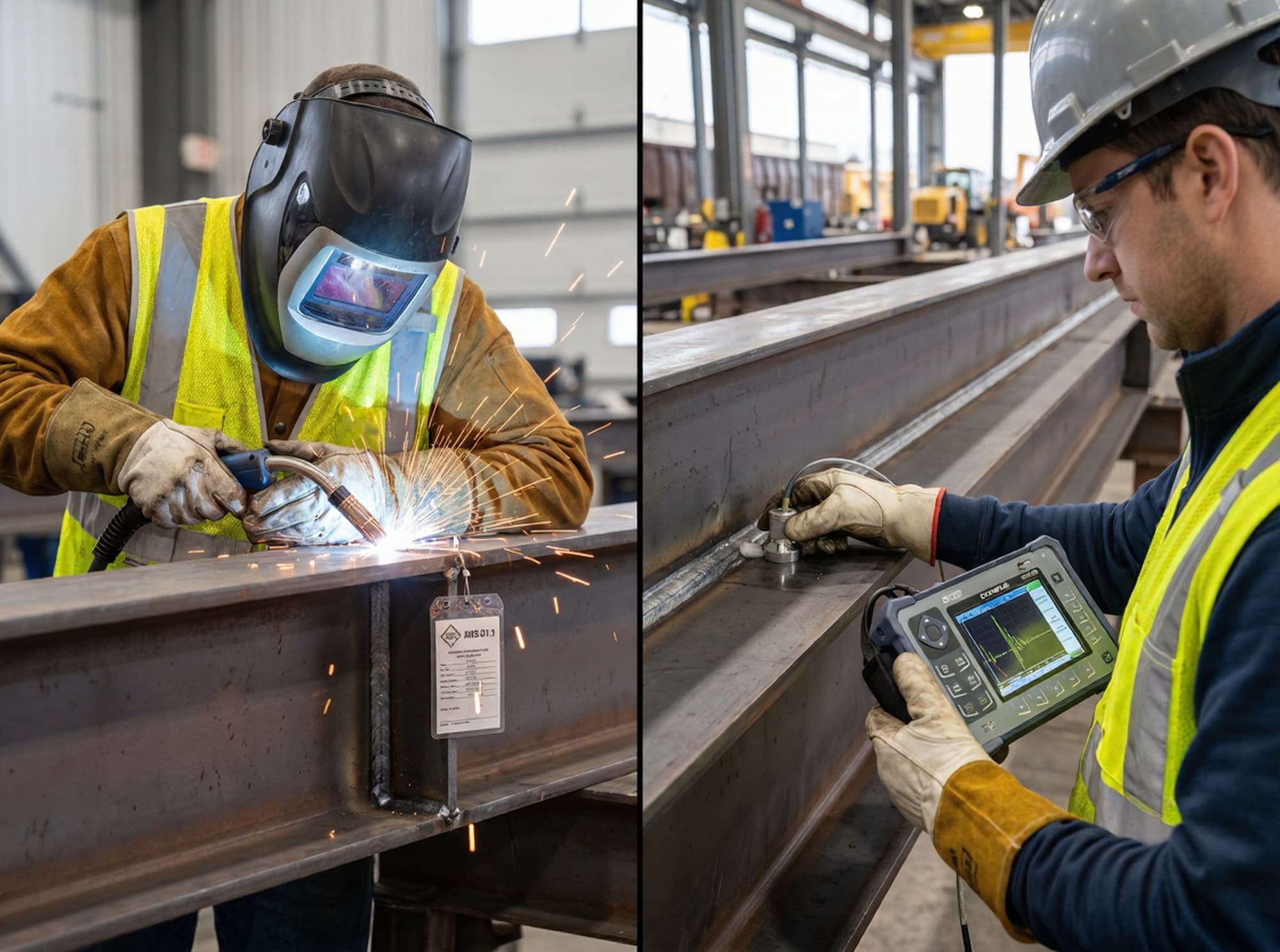
AWS D1.1 acceptance criteria are the limits in the Structural Welding Code – Steel that decide whether a weld is accepted or repaired. Every weld gets visual inspection and no crack is accepted. Ultrasonic testing (UT) is required only when the contract calls for it, and its indications are classed A to D from the rating d = a − b − c.
The current edition from the American Welding Society (AWS) is AWS D1.1/D1.1M:2025, which AWS announced on April 17, 2025. Many projects are still contracted to the 2020 edition, so the edition named in your contract documents is the one that governs.
Contents: Where the criteria live · Visual limits · Does D1.1 require UT? · Why UT? · UT rating · Classes A–D · Worked example · Step by step · Common mistakes · Calibration · Personnel · Limits · FAQ
About clause and table numbers: AWS D1.1 is paywalled, so the numbers below come from AWS publications and secondary summaries of the 2020 and 2025 editions. Check every limit against the edition named in your contract before accepting or rejecting a weld.
Where are the AWS D1.1 acceptance criteria in the code?
In the 2020 and 2025 editions, inspection and acceptance criteria sit in Clause 8, "Inspection." The 2020 edition reorganized D1.1 from 9 clauses to 11, which is why older references to "Clause 6" and "Table 6.1" now point to Clause 8 and Table 8.1.
| Item | D1.1:2020 and 2025 | D1.1:2015 and earlier |
|---|---|---|
| Inspection clause | Clause 8 | Clause 6 |
| Visual acceptance criteria | Table 8.1 | Table 6.1 |
| UT acceptance-rejection criteria, statically loaded nontubular | Table 8.2 | Table 6.2 |
| UT acceptance-rejection criteria, cyclically loaded nontubular | Table 8.3 | Table 6.3 |
| UT of groove welds (procedure) | Clause 8, Part F | Clause 6, Part F |
| Tubular structures | Clause 10 | Clause 9 |
Table 8.1 has separate columns for statically loaded nontubular, cyclically loaded nontubular and tubular connections. A limit quoted without its column is not a usable limit. Most building framing is statically loaded; fatigue-sensitive members such as crane runway girders are cyclically loaded, and the engineer designates which applies.
Key takeaway: always ask "static, cyclic or tubular?" before quoting any D1.1 limit.
What is the difference between a discontinuity and a defect?
A discontinuity is any interruption in the normal structure of a weld; a defect is a discontinuity that exceeds the code's acceptance criteria. Porosity or undercut within the limits is acceptable; only discontinuities that exceed the applicable table need repair. Cracks are the exception, rejected at any size.
What are the AWS D1.1 visual acceptance criteria?
Every weld under D1.1 must pass visual inspection (VT) against Table 8.1, and the limits for undercut and porosity depend on whether the connection is statically or cyclically loaded. The table below summarizes the nontubular columns. Tubular connections have their own column and their own undercut limits.
| Table 8.1 item | Statically loaded nontubular | Cyclically loaded nontubular |
|---|---|---|
| Cracks | Not accepted, regardless of size or location | Not accepted, regardless of size or location |
| Weld/base metal fusion | Complete fusion required between adjacent layers and between weld and base metal | Same |
| Crater cross section | Craters filled to the full weld size (except ends of intermittent fillet welds outside their effective length) | Same |
| Weld profile | Must meet the Clause 7 profile requirements (convexity, reinforcement, no overlap) | Same |
| Undercut | Material under 1 in.: max 1/32 in. (1/16 in. allowed for an accumulated 2 in. in any 12 in.). Material 1 in. and thicker: max 1/16 in. for any length | Primary members, weld transverse to tensile stress: max 0.01 in. All other cases: max 1/32 in. |
| Piping porosity, CJP groove welds in butt joints transverse to tensile stress | None visible | None visible |
| Piping porosity, all other groove and fillet welds | Sum of visible pores 1/32 in. and larger: max 3/8 in. in any linear inch and max 3/4 in. in any 12 in. of weld | Max one pore in each 4 in. of weld length; max diameter 3/32 in. |
| Undersized fillet welds | A limited underrun of nominal size is allowed over no more than 10% of the weld length; none at the ends of girder web-to-flange welds for a length equal to twice the flange width | Same |
Sources: Table 8.1 as summarized in 2025-edition CWI study material and AWS forum quotations of the code text. Confirm values against your edition.
Two limits are often misquoted. The 3/32 in. pore diameter belongs to the cyclic frequency rule; static welds use the sum-of-diameters rule. The 0.01 in. undercut limit applies to cyclically loaded primary members with the weld transverse to tensile stress, not to every primary member.
Worked example: one undercut, three answers
A fillet weld joining 3/4 in. plates has undercut 3/64 in. (about 0.047 in.) deep along one toe. Its accumulated length is 1½ in. within a 12 in. length of weld.
- Statically loaded: the material is under 1 in., so the base limit is 1/32 in. (0.031 in.). The undercut is deeper than that but within the 1/16 in. (0.0625 in.) allowance, and its accumulated length of 1½ in. is under the 2 in. allowed in any 12 in. Accept.
- Cyclically loaded primary member, weld transverse to tensile stress: the limit is 0.01 in., and 0.047 in. is 4.7 times that. Reject and repair.
- Cyclically loaded, any other case: the limit is 1/32 in. The cyclic column has no length allowance, so 3/64 in. fails. Reject.
If the same undercut ran 3 in. within the 12 in. length, the static answer would also become a reject, because it would exceed the 2 in. accumulated allowance. Depth and length must both be measured, normally with an undercut gauge, and recorded with the loading column used.
When can visual inspection start?
Visual inspection may begin as soon as the completed weld has cooled to ambient temperature, except for the highest-strength quenched and tempered steels. For ASTM A514, A517 and A709 Grade HPS 100W (690W), acceptance is based on inspection performed at least 48 hours after welding. TWI quotes the earlier D1.1:2010 wording directly:
"NDT performed not less than 48 hours after completion of the welds." (AWS D1.1:2010, para. 6.11, as quoted by TWI)
The delay exists because hydrogen-assisted cold cracking can appear several hours after the weld cools.
Key takeaway: visual limits are only meaningful with their loading column, and on 100 ksi steels the clock starts 48 hours after welding.
Which inspection methods does AWS D1.1 recognize?
D1.1 recognizes visual testing on every weld, plus magnetic particle, penetrant, radiographic and ultrasonic testing when the contract documents specify them. The 2020 edition also added a normative annex for phased array ultrasonic testing (PAUT).
| Method | What it finds | Main limit | D1.1 acceptance basis |
|---|---|---|---|
| Visual testing (VT) | Surface cracks, undercut, porosity, profile, size | Surface only | Table 8.1 |
| Magnetic particle (MT) | Surface and near-surface discontinuities | Ferromagnetic steel only; shallow depth | Evaluated against the visual criteria |
| Penetrant (PT) | Surface-breaking discontinuities | Must be open to the surface | Evaluated against the visual criteria |
| Radiographic (RT) | Volumetric flaws: porosity, slag | Planar flaws (lack of fusion, cracks) can be missed if not aligned with the beam | Separate RT criteria for static, cyclic and tubular |
| Ultrasonic (UT) | Planar and volumetric internal flaws in groove welds | Operator-dependent; Part F covers a defined thickness range | Tables 8.2 (static) and 8.3 (cyclic) |
| Phased array (PAUT) | As UT, with imaging | Needs a written procedure under the PAUT annex | Annex criteria |
For a wider comparison, see our guide to non-destructive testing for welding inspection.
Does AWS D1.1 require ultrasonic testing?
No. AWS D1.1 does not by itself require UT on any weld. Visual inspection is the baseline. When NDT other than visual is required, the code expects it to be stated in the information furnished to bidders, including which categories of welds are tested, the extent of testing and the method. D1.1 lists full, partial and spot testing as the extents of testing.
The requirement to UT a weld usually comes from somewhere else:
| Source of the UT requirement | Typical rule |
|---|---|
| Project specification or drawings | The engineer of record names the welds, method and extent |
| AISC 360, Chapter N (steel buildings) | QA performs UT on CJP groove welds in butt, T- and corner joints subject to transversely applied tension, in material 5/16 in. and thicker: all such welds in Risk Category III or IV, 10% in Risk Category II |
| AISC 341 (seismic force-resisting systems) | UT on 100% of CJP groove welds in material 5/16 in. and thicker |
| AWS D1.5 (bridges) | Bridge code with its own NDT extent rules; D1.1 doesn't govern bridges |
The AISC figures above are as quoted in published secondary sources from AISC 360-10 onward. AISC standards are free to download from aisc.org; read Chapter N of the edition your building code adopts.
Where the "5/16 in." figure comes from
The 5/16 in. figure appears in two different places, which is why it is often misread as a D1.1 mandate:
- AISC 360 Chapter N uses 5/16 in. as the thickness above which certain CJP welds must be ultrasonically tested.
- D1.1 Part F uses 5/16 in. as the bottom of the thickness range its UT procedures and standards cover. Older editions quoted on the AWS forum set that range at 5/16 in. to 8 in. (8 mm to 200 mm). That range says how to perform UT when it is required. It doesn't say when UT is required.
Worked example: how many welds need UT?
A steel-framed office building (Risk Category II) has 60 CJP groove welds in moment-connection beam flanges, 3/4 in. thick, loaded in transverse tension.
- Under AISC 360 Chapter N, QA must ultrasonically test 10% of them: 6 welds.
- If the same building were a hospital (Risk Category IV), all 60 welds would need UT.
- If the frame were part of a seismic force-resisting system under AISC 341, all 60 would be tested.
- In every case, D1.1 Part F governs how the UT is done, and Table 8.2 or 8.3 governs acceptance.
Key takeaway: D1.1 tells you how to perform and judge UT; the contract, AISC 360 or AISC 341 tells you whether to perform it.
Why is ultrasonic testing used on structural welds?
Ultrasonic testing of welds is specified under AWS D1.1 because visual inspection, the code's baseline for every weld, sees only the surface, while the discontinuities that most weaken a complete joint penetration (CJP) groove weld, lack of fusion and cracks, usually lie inside it. UT sends an angle beam through the weld from the adjacent base metal, needs access to one surface only, and involves no radiation. That is why D1.1 gives UT its own procedure (Part F) and its own acceptance tables (8.2 and 8.3), and why AISC 360 Chapter N and AISC 341 specify UT for the CJP welds they require to be tested.
The table below sorts the common D1.1 discontinuities by where they sit and which method is the right first choice. Lack of fusion and cracks are planar: thin, flat and oriented along the fusion face or across the weld. Porosity and slag are volumetric: rounded or elongated pockets with a measurable width.
| Discontinuity | Type and location | Visual | MT or PT | RT | UT |
|---|---|---|---|---|---|
| Crack (surface-breaking) | Planar, open to the surface | Finds it if open and visible | Best choice on steel (MT) | Finds it if aligned with the beam | Finds it; a strong reflector when the beam hits it face-on |
| Crack (subsurface) | Planar, inside the weld or heat-affected zone | Cannot see it | MT reaches only shallow depth | Can miss it if not aligned with the beam | The method of choice |
| Lack of fusion | Planar, on the sidewall or between runs | Cannot see it | Only if it breaks the surface | Often missed: thin and oblique to the beam | The method of choice; a weak echo if the beam strikes it at a poor angle |
| Incomplete joint penetration | Planar, at the root | Only from the root side, if accessible | Only if it breaks the surface | Usually visible as a straight dark line | Found from the root side; both-sides scanning helps |
| Porosity | Volumetric, scattered or clustered | Only surface pores (Table 8.1 piping porosity) | Surface pores only | Best choice: a permanent image with pore count and size | Found, but amplitude varies with probe rotation |
| Slag inclusion | Volumetric, elongated along the weld | Cannot see it | Only if it breaks the surface | Readily identified as an elongated line | Found; its echo can be weaker than porosity of the same size |
| Undercut, overlap, profile | Surface, at the weld toe | Table 8.1 with an undercut gauge | Not needed | Not the right tool | Not the right tool |
TWI's job-knowledge note on lack of fusion says that subsurface fusion imperfections are detected "by radiography or ultrasonic inspection", then makes the central point:
"Ultrasonic inspection is normally more effective than radiography in detecting lack of inter-run fusion imperfections." (TWI, Job Knowledge 41)
The reason is geometry. A radiograph records the loss of beam intensity through the weld thickness, so a flat flaw that is thin in the beam direction removes almost nothing from the image unless the beam runs along its plane. A shear-wave beam is reflected by that same flat face, and an angle-beam search unit can be chosen to meet a sidewall fusion face close to square-on. For the same reason, radiography stays the better choice for porosity and slag: it images them directly and leaves a film or digital record that a second reviewer can read without re-scanning.
Where UT is not the right first choice
- Surface-breaking discontinuities. D1.1 evaluates MT and PT indications against the Table 8.1 visual criteria, and on structural steel MT is the direct way to find toe cracks, surface lack of fusion and crater cracks. The region just under the scanning surface is the hardest for angle-beam UT to cover, and weld-cap and root geometry produce echoes of their own that have to be separated from flaw echoes.
- Volumetric discontinuities where a record matters. When the contract calls for RT on butt joints, it is usually because the engineer wants a film record of porosity and slag. On a plate butt joint RT needs the source on one side of the weld and the detector on the other, a controlled area around the exposure, and a licensed radiography program; under NRC rules a field radiographer "must be accompanied by at least one other qualified radiographer" and "Radiography may not be performed if only one qualified individual is present" (10 CFR 34.41(a)). UT needs one technician, a couplant and a clean surface.
- Thin material. Part F is written for 5/16 in. (8 mm) to 8 in. (200 mm). Outside that range the contract has to specify another method or a written UT procedure of its own.
What UT can and cannot say about a flaw it finds
UT is sensitive to planar flaws, but it is not a sizing instrument in the way a radiograph is a ruler. Three limits follow from the rating method in the next section:
- Amplitude is not size. The rating d = a − b − c compares the echo with a 0.060 in. side-drilled hole. A large, smooth lack of fusion met at a poor angle can return a weak echo and rate as Class D, and a tight, closed fusion face that transmits sound can return almost nothing. UT does not "find the smallest flaws" in any absolute sense; Class D exists because minor indications are accepted.
- Length comes from the 6 dB drop, not from the flaw. The measured length of a reflector shorter than the beam width is the beam width, so D1.1's 3/4 in. and 2 in. length limits are only as sharp as the beam that measures them.
- Flaw type is a judgment, not a reading. The screen shows amplitude against time. Whether an indication is lack of fusion, a crack or a slag line comes from its position in the joint, how it behaves as the probe moves, and the technician's training. That is why D1.1 asks for Level II personnel (or a Level I working under a Level II) and why a crack identified by any method is rejectable regardless of rating.
Key takeaway: D1.1 pairs UT with visual inspection because the two see different things; UT is chosen for planar subsurface flaws, MT or PT for the surface, and RT where a volumetric record is wanted.
How are UT indications rated under AWS D1.1?
D1.1 rates each UT indication in decibels with the formula d = a − b − c, then compares the rating with an acceptance table for the weld thickness, search-unit angle and loading type. It is not a fixed "+10 dB rejects, −6 dB accepts" scale.
| Term | Meaning | How it is found |
|---|---|---|
| a | Indication level (dB) | Gain needed to bring the peak signal from the discontinuity to the reference line on the screen |
| b | Reference level (dB) | Gain needed to bring the reflection from the 0.060 in. (1.5 mm) side-drilled hole in an IIW-type block to the same reference line |
| c | Attenuation factor (dB) | 2 × (sound path in inches − 1), i.e. 2 dB per inch of sound path beyond the first inch (metric: 0.08 dB per mm beyond 25 mm) |
| d | Indication rating (dB) | a − b − c |
A lower (more negative) rating means a stronger reflector. If the indication needs less gain than the reference hole to reach the reference line, a is smaller than b and d goes negative. That is why the most severe class, Class A, sits at the low end of each table.
Evident's AWS weld inspection tutorial gives the same formula, and Holloway (CINDE Journal, 2017) traces the 2 dB/in. model back to AWS D1.0 in 1969. ANSI's summary of D1.1:2025 says the new edition changed how c is handled on instruments that display fractional dB, so use the rounding rule in your edition.
What scanning level is used?
Scanning is done at a gain above the reference level that increases with sound path, and it is higher for cyclically loaded welds. Published summaries of the UT tables give these scanning levels:
| Sound path | Statically loaded (dB above reference) | Cyclically loaded (dB above reference) |
|---|---|---|
| Up to 2½ in. | 14 | 20 |
| Over 2½ to 5 in. | 19 | 25 |
| Over 5 to 10 in. | 29 | 35 |
| Over 10 to 15 in. | 39 | 45 |
Scanning gain finds indications; each is then rated at the reference line.
How do Classes A, B, C and D decide accept or reject?
The class comes from the indication rating d read against the table row for the weld thickness and search-unit angle; the length limit for that class then decides acceptance. The same rating can be Class A in one thickness band and Class C in another.
| Class | Description | Statically loaded (Table 8.2) | Cyclically loaded (Table 8.3) |
|---|---|---|---|
| A | Large discontinuity | Reject regardless of length | Reject regardless of length |
| B | Medium discontinuity | Reject if longer than 3/4 in. | Reject if longer than 3/4 in. |
| C | Small discontinuity | Reject if longer than 2 in. | Reject if longer than 2 in. in the middle half of the weld thickness, or longer than 3/4 in. in the top or bottom quarter |
| D | Minor discontinuity | Accept regardless of length or location | Accept regardless of length or location |
The thickness-dependent length rule belongs to the cyclic table. In the static table, Class B and C length limits don't change with position through the thickness.
The rating bands that set each class vary by thickness and angle. Two rows of the static table are quoted on the AWS forum for a 70° search unit:
| Weld thickness (static, 70°) | Class A | Class B |
|---|---|---|
| 5/16 to 3/4 in. (8 to 20 mm) | +5 and lower | +6 |
| Over 3/4 to 1½ in. (20 to 38 mm) | +2 and lower | +3 |
Thicker bands (over 1½ in. up to 8 in.) give separate columns for 70°, 60° and 45° search units, and the cyclic table uses its own, more demanding bands. Read the Class C and D boundaries from the table in your edition rather than from a summary.
Table notes add further rules. Class B and C indications closer together than 2L (L being the length of the longer indication) are treated as one, and Class B and C indications may not begin within 2L of weld ends carrying primary tensile stress. Indication length is normally measured by the 6 dB drop method at each end.
Key takeaway: a class is never a fixed dB band; it is the rating d looked up against thickness, angle and loading.
Worked example: rating and classing a UT indication
Setup. A 1 in. thick CJP groove weld in a statically loaded butt joint is scanned with a 70° search unit. The reference level from the 0.060 in. side-drilled hole is b = 48 dB.
Indication 1. The technician peaks a reflector and brings it to the reference line at a = 53 dB. The sound path is 2.5 in.
- Attenuation: c = 2 × (2.5 − 1) = 3 dB
- Rating: d = 53 − 48 − 3 = +2
- Depth check: 2.5 in. × cos 70° ≈ 0.86 in. below the scanning surface, inside the 1 in. weld
- Class: in the over 3/4 to 1½ in. row at 70°, +2 is Class A
- Result: reject, regardless of length
Indication 2. A second reflector at the same sound path needs a = 54 dB.
- d = 54 − 48 − 3 = +3, which is Class B
- Its length by 6 dB drop is 5/8 in., under the 3/4 in. limit
- Result: acceptable, provided it isn't within 2L of another Class B or C indication or of a weld end carrying primary tension
The same rating in a different joint. One published summary works through a 60° search unit in the over 1½ to 2½ in. band. There, a rating of +4 is Class C under the static table (accepted unless longer than 2 in.), but Class A under the cyclic table, which places Class A at +7 and lower in that column. One number, two loading cases, opposite results.
What a rating doesn't tell you: the flaw type. Lack of fusion, a crack and a slag line can all rate +2, and a crack identified by any method is rejectable regardless of rating.
How is an AWS D1.1 UT examination carried out, step by step?
A D1.1 UT examination runs from the contract documents to the report: confirm the basis, scan the base metal, calibrate, scan the weld from both sides, then rate, class and record every indication. The sequence below follows the Part F structure as described in secondary sources; clause and table numbers differ between editions, so confirm them in yours.
- Confirm the basis. Read the edition, the loading category and the extent of testing (full, partial or spot) from the contract documents. The loading category decides whether Table 8.2 or Table 8.3 applies, and that has to be settled before scanning, not after an indication is found.
- Prepare the scanning surface. Remove spatter, loose scale and anything else on either side of the weld that would interfere with coupling.
- Scan the base metal with a straight beam. Part F calls for a 0° scan of the base metal the angle beam will travel through, because a lamination there can hide a weld flaw or redirect the beam and produce a false indication.
- Calibrate distance and reference level. Set the range and find b on the 0.060 in. side-drilled hole of an IIW-type block. Earlier editions, as quoted on the AWS forum, require the search unit's refracted angle to be within ±2° of 70°, 60° or 45°.
- Pick angles from the testing procedure chart. The chart (Table 6.7 before the 2020 renumbering) assigns angles by thickness and weld zone. Forum reproductions of older editions show procedures that mix angles by depth, for example 60° for the top quarter and 70° for the middle half and bottom quarter.
- Scan at scanning level. Use the scanning gain for the sound path and loading case, and scan from both sides of the weld axis where access allows. D1.1:2020 Clause 8 is quoted as requiring testing from both sides "wherever mechanically possible."
- Evaluate each indication. Peak it, bring it to the reference line to get a, compute c from the sound path and calculate d. Check the depth against the plate thickness, read the class from the correct row and angle column, and measure length by the 6 dB drop method.
- Recalibrate and report. Recheck calibration at the intervals below, and record every indication evaluated, whether it was accepted or rejected, with its location, a, b, c, d, class and length.
What mistakes are common when applying AWS D1.1 acceptance criteria?
Most wrong accept or reject decisions under D1.1 come from using the wrong reference, the wrong table or the wrong measurement, not from misreading the screen. These errors recur in procedures and reports:
- Treating D1.1 as a DAC code. D1.1 rates every indication against one reference reflector, the 0.060 in. side-drilled hole, and corrects for distance with the attenuation factor c. Building a distance-amplitude correction (DAC) curve and reporting "% DAC" belongs to ASME practice. A D1.1 report needs a, b, c and d.
- Reading the wrong angle column. In the thicker bands the class boundaries differ by search-unit angle, so a rating taken with a 60° probe but looked up in the 70° column can return the wrong class.
- Citing a superseded table. A procedure written to D1.1:2015 cites Table 6.2 for static UT acceptance; the same subject is Table 8.2 in the 2020 and 2025 editions. The procedure and report should name the edition the contract invokes, so a reviewer can check the right table.
- Overstating length. Measuring an indication to the point where the echo disappears, rather than at the 6 dB drop points, makes it longer than the code method does. That can push a Class B indication past its 3/4 in. limit.
- Rounding c inconsistently. ANSI's summary of D1.1:2025 notes a change in how c is handled on instruments that display fractional dB. In the worked example above, one decibel separates Class A (+2) from Class B (+3), so the rounding rule in your edition matters on boundary indications.
How often must UT equipment be recalibrated?
UT equipment must be recalibrated after a change of operator, at a maximum interval of 30 minutes, and whenever the electrical circuitry is disturbed. Published summaries of the code list these disturbances:
- transducer change
- battery change
- electrical outlet change
- coaxial cable change
- power outage
A "recheck every two hours" is not the D1.1 interval. Confirm the interval and clause in your edition, because a 2011 AWS Inspection Trends article discussed a revision to the operator-change rule. Record each distance and amplitude calibration on the UT report.
The code also limits search-unit size and frequency. Holloway notes the most common AWS angle-beam probe is 2.25 MHz with a 5/8 × 5/8 in. element, which is also the smallest the code allows, so small high-frequency probes from other work don't meet the D1.1 procedure.
Who is qualified to inspect under AWS D1.1?
Visual inspection and UT need different qualifications. A CWI (or equivalent) performs visual inspection; NDT personnel qualified under ASNT SNT-TC-1A perform UT. The AWS Certified Associate Welding Inspector (CAWI) credential is not a UT qualification.
| Role | Qualification D1.1 looks for | Notes |
|---|---|---|
| Inspector (visual and general inspection) | AWS Certified Welding Inspector (CWI) or Senior CWI under AWS QC1; CWB-certified inspector under CSA W178.2; or a person the engineer accepts on training and experience | Periodic eye examination required |
| Assistant inspector | Works under the inspector's supervision | A CAWI fits here |
| UT technician | Qualified under the current edition of ASNT SNT-TC-1A: NDT Level II, or Level I working under a Level II | Certification of Level I and II is performed by a Level III |
| PAUT technician | As above, plus the PAUT annex procedure requirements |
The AWS description of the CAWI makes the supervision explicit:
"A CAWI performs inspections alongside a SCWI or CWI, who determines final acceptance." (AWS, CAWI certification)
SNT-TC-1A is a recommended practice: the employer certifies its own NDT personnel under a written practice approved by its Level III. Neither AWS nor ASNT issues an SNT-TC-1A certificate to the individual. Our guide to SNT-TC-1A requirements covers how that works.
AWS D1.8, the seismic supplement, contains a formal UT technician performance exam. Thomas Hay's February 2025 Inspection Trends article on NDE personnel qualification to AWS structural and bridge codes describes it: at least 20 indications across multiple specimens, an overall rating of 0.90 or higher, a detection rating of 0.87 or higher and a false-call rating of 0.15 or less. The same article puts UT Level II training at a minimum of 80 classroom hours and 630 hours of supervised experience.
For buyers: ask for the UT technician's employer certification record and the written practice it was issued under, not only a CWI card. A CWI who isn't also a qualified UT technician can't sign off a UT examination.
How do the three phases of inspection fit together?
D1.1 inspection happens before, during and after welding; the acceptance criteria apply to the last phase, and the first two prevent rejections.
| Phase | What the inspector checks |
|---|---|
| Before welding | Applicable WPS, current welder qualifications, base metal, fit-up, root opening, cleanliness, preheat |
| During welding | Preheat and interpass temperature, electrode handling, technique, cleaning between passes |
| After welding | Table 8.1 visual criteria, weld size and profile, then any specified NDT |
Contractor's inspection or verification inspection?
D1.1 splits inspection between two parties. AWS's own Inspection Trends sets out the split for D1.1:2020: Daryl Peterson's February 2023 article on quality assurance and quality control places contractor's inspection in clause 8.1.2.1 and verification inspection in clause 8.1.2.2.
- Contractor's inspection is quality control. Unless the contract documents say otherwise, the contractor is responsible for inspection and testing before assembly, during assembly and welding, and after welding, to confirm that materials and workmanship meet the contract documents. The contractor also writes the WPSs and qualifies the welders.
- Verification inspection is quality assurance for the owner, performed by the owner's staff or a third-party inspector. It is largely an audit of WPSs, welder qualification records, material test reports, NDT reports and personnel certifications, with product inspection to the extent the contract sets or where the contractor's results are in doubt.
The article stresses speed: verification results are to be "promptly reported to the owner and contractor to avoid delays in the work." On a project with both, the same weld can be ultrasonically tested twice. When the two results disagree, matching records of edition, loading column, angle, reference level and attenuation are what let the parties find out why.
A D1.1 WPS is either prequalified or qualified by test with a procedure qualification record (PQR). See our guide to WPS and PQR.
What AWS D1.1 acceptance criteria don't cover
The D1.1 tables are minimum workmanship criteria for carbon and low-alloy structural steel; they don't cover every structure, every joint or every flaw.
| Situation | Why D1.1 acceptance criteria may not apply or may not be enough |
|---|---|
| Highway bridges | Governed by AWS D1.5, with its own NDT extent and acceptance rules |
| Seismic force-resisting systems | AWS D1.8 and AISC 341 add requirements on top of D1.1 |
| Sheet steel, stainless, aluminum | Covered by other AWS D1 codes (D1.3, D1.6, D1.2) |
| Pressure vessels and piping | ASME Section VIII and B31 with Section IX qualification; see our ASME weld UT guide |
| Project specification stricter than the code | The contract governs; D1.1 is the floor |
The UT method has its own limits:
- The 2 dB/in. attenuation factor is an approximation. Holloway's 2017 modeling found it matched within about 2 dB at 45°, but at 60° and 70° the difference grew to nearly 6 dB at sound paths around 150 mm (6 in.). On thick welds, that can move an indication across a class boundary.
- Amplitude doesn't equal size. A smooth planar flaw at a poor angle to the beam can return a weak echo and rate as Class D.
- Geometry matters. Thin material below the Part F range, partial joint penetration welds and complex tubular T-, Y- and K-connections need procedures written for them; the Part F tables don't apply automatically.
- Surface condition. Spatter, rough weld caps and coatings reduce coupling and can hide indications near the surface.
How EMA Industries applies this
EMA Industries performs AWS D1.1 structural weld UT, MT and PT, provides NDT Level III services and supports WPS and PQR work. We're based in Southern California and mobilize nationwide. On D1.1 projects, the edition, loading category (static or cyclic) and NDT extent should be confirmed from the contract documents before scanning starts, and the UT report should record the reference level, attenuation factor, rating, class and length of every indication evaluated. See our ultrasonic testing services (and our guide to NDT welding inspection) or contact EMA Industries to scope an inspection.
Related reading: UT acceptance criteria across codes · Weld defect types · Lack of fusion in welds · Phased array ultrasonic testing
Frequently asked questions
Is ultrasonic testing mandatory under AWS D1.1?
No. D1.1 requires visual inspection of every weld, but UT is required only when the contract documents specify it. In steel buildings, the requirement usually comes from AISC 360 Chapter N or, for seismic systems, AISC 341.
What are the AWS D1.1 UT acceptance criteria?
Each indication is rated with d = a − b − c, where a is the indication level, b the reference level and c the attenuation factor of 2 dB per inch of sound path beyond 1 in. The rating is looked up in Table 8.2 (static) or 8.3 (cyclic) by weld thickness and search-unit angle to give Class A, B, C or D. Class A rejects at any length, Class B over 3/4 in., Class C over 2 in. (static), and Class D is accepted.
What is the maximum undercut allowed by AWS D1.1?
It depends on the loading and thickness. For statically loaded nontubular connections, undercut is limited to 1/32 in. on material under 1 in. thick (with 1/16 in. allowed over 2 in. in any 12 in.) and 1/16 in. on thicker material. For cyclically loaded primary members with the weld transverse to tensile stress, the limit is 0.01 in.
Can a CAWI or CWI perform UT under D1.1?
Not on the strength of that credential. A CAWI works under a CWI or SCWI on inspection tasks, and a CWI performs visual and general inspection. UT must be performed by personnel qualified under SNT-TC-1A as Level II, or Level I working under a Level II. One person can hold both qualifications.
How long does an AWS D1.1 welder qualification last?
Indefinitely, with two conditions. As quoted from the 2015 edition on the AWS forum, a welder's qualification remains in effect unless the welder has not used that welding process for more than six months, or there is a specific reason to question the welder's ability. A lapsed qualification needs a requalification test. The code doesn't prescribe a continuity log, so employers use records such as job tickets to show each process was used within six months. Confirm the clause in your edition.
What is the difference between AWS D1.1 and ASME Section IX?
D1.1 is a complete code for welded structural steel: it covers the design of welded connections, procedure and welder qualification, fabrication, and inspection with acceptance criteria. ASME Section IX only qualifies welding, brazing and fusing procedures and the people who perform them, for work that other ASME Boiler and Pressure Vessel Code sections require. It has no acceptance criteria for production welds; those come from the construction code, such as Section VIII or B31.3. A qualification under one code doesn't automatically satisfy the other.
Sources
- AWS announces release of D1.1/D1.1M:2025, Structural Welding Code – Steel, American Welding Society, April 17, 2025
- What's New in AWS D1.1 2025, Structural Welding Code — Steel, Welding Journal, May 2025 (summary; full text for members)
- Quality Assurance vs. Quality Control, D. Peterson, Inspection Trends, February 2023 (D1.1:2020 clauses 8.1.2.1 and 8.1.2.2)
- NDE Personnel Qualification and Performance to AWS Structural and Bridge Welding Codes, T. R. Hay, Inspection Trends, February 2025
- Certified Associate Welding Inspector (CAWI), American Welding Society
- ASNT Recommended Practice No. SNT-TC-1A (2024), American Society for Nondestructive Testing
- Ultrasonic flaw detection tutorial: AWS weld inspection, Evident Scientific
- Structural UT: Variables Affecting Attenuation and Review of the 2 dB per Inch Model, P. Holloway, CINDE Journal Vol. 38 No. 3, May/June 2017
- Which standards stipulate a delay time before inspecting welds?, TWI
- Weld defects/imperfections in welds: lack of sidewall and inter-run fusion (Job Knowledge 41), TWI
- 10 CFR 34.41, Conducting industrial radiographic operations, Nuclear Regulatory Commission (read on Cornell LII)
- AWS D1.1/D1.1M:2020 and :2025, Structural Welding Code – Steel, Clause 8 and Tables 8.1–8.3 (paywalled; values above taken from the secondary sources listed and must be confirmed against the licensed text)
- ASME BPVC Section IX, Welding, Brazing, and Fusing Qualifications, 2025 edition (scope as given in publisher and retailer listings)
- AWS forum quotations of D1.1:2015 welder qualification period of effectiveness (app.aws.org; snippets only, to be confirmed against the licensed text)
- ANSI/AISC 360, Specification for Structural Steel Buildings, Chapter N, Section N5.5 (free from AISC; quoted here from secondary sources)