
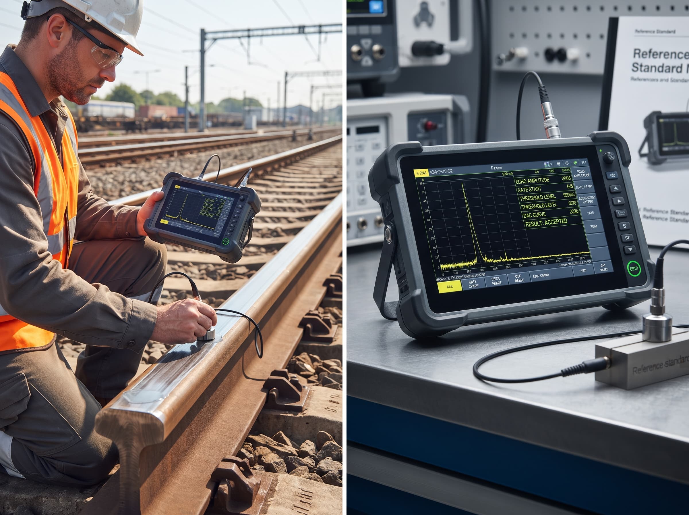
Ultrasonic testing acceptance criteria becomes particularly important in 2026, as several ultrasonic testing standards are now available in updated editions. ASTM's current standards include documents such as E164-24, E273-25, E2700-26, E3517/E3517M-26, and E2375-26a. ISO 16810:2024 also remains an important reference for the general principles of industrial ultrasonic testing.
For inspectors, engineers, and quality professionals, keeping track of these standards is only part of the job. The real challenge is knowing which standard applies to a particular inspection and understanding how its requirements should be used when evaluating an indication.
What Determines Whether an Ultrasonic Testing Acceptance Criteria Is Acceptable?
The ultrasonic testing acceptance criteria decision begins with the application. A weld in a pressure vessel does not necessarily follow the same requirements as a structural steel weld, pipeline girth weld, or rolled steel plate.
Several factors for ultrasonic testing acceptance criteria normally establish the applicable acceptance framework:
· Component: weld, pipe, plate, forging, valve, or pressure vessel.
· Governing document: ASME, AWS, API, ASTM, ISO, project specification, or contract.
· Indication characteristics: type, amplitude, length, location, orientation, and distribution.
· Material and thickness: acoustic properties and section thickness affect examination and evaluation.
· Service requirements: component criticality and design conditions can influence the specified quality level.
For example, ASTM E164-24 provides a practice for contact ultrasonic examination of specific weld configurations. ASTM states that when UT becomes the basis for weld acceptance, the manufacturer and purchaser should agree on the reference standards and limits, with a detailed examination procedure describing allowable discontinuity limits.
That point is easy to overlook. A UT operator can locate and characterize an indication correctly while still needing a separate document to determine whether the indication is acceptable.
Examination Standard vs Acceptance Criteria
The difference can be understood through a simple sequence:
Written procedure → calibration → examination → indication → evaluation → acceptance decision
This distinction is particularly clear in ISO 16810:2024. The standard establishes general principles for industrial ultrasonic testing, while its scope specifically excludes acceptance criteria, scan plans, and the extent of testing. ISO explains that application-specific requirements can instead appear in product standards, specifications, codes, contractual documents, or written procedures.
Consequently, an inspector should not assume that a general UT standard provides a universal rejection value. The applicable construction or product document must be identified first.
The same principle applies when interpreting ultrasonic testing acceptance criteria under ASTM documents. Some ASTM practices establish examination methods, while others include acceptance classifications or product-specific acceptance requirements.
Once the correct document has been identified, the next issue is understanding what the major standards actually contribute to the inspection process.
Ultrasonic Testing Acceptance Criteria Standards in 2026
ASME Standards
ASME requirements are particularly important for pressure vessels, piping, valves, and other pressure-containing equipment. The exact acceptance requirement depends on the construction code and application.
ASME Section V primarily establishes nondestructive examination requirements and methods. It should not automatically be treated as a universal acceptance table. The construction code using Section V can establish the requirements for evaluating and accepting the examined component.
ASME Section VIII becomes relevant to pressure-vessel construction. Its requirements must be read together with the applicable examination provisions and project documentation when making an acceptance decision.
ASME B31.1 addresses power piping, while ASME B31.3 addresses process piping. Both are important where welds are examined ultrasonically, but the applicable piping code and project requirements determine the acceptance basis.
ASME B16.34 is relevant to valves and includes requirements associated with examination of valve components.
The important lesson is that an ASME reference should always be accompanied by its specific application and applicable edition. A statement such as “ASME allows this indication” can be misleading if the component, examination method, or construction-code requirement differs.
API 1104
API Standard 1104 is a major reference for pipeline welding. API’s 22nd edition covers gas and arc welding for the construction and in-service repair of pipes and components used in pipeline transmission applications. The edition also updated requirements involving ultrasonic and radiographic inspection of girth welds.
For pipeline work, evaluation can involve the nature, location, size, and distribution of indications. Linear indications, incomplete penetration, lack of fusion, and volumetric indications cannot simply be judged using a generic weld acceptance table.
The pipeline application therefore requires the inspection procedure and the applicable API requirements to be read together.
AWS D1.1
AWS D1.1 is central to structural steel welding. The current AWS page identifies AWS D1.1/D1.1M:2025 and notes refinements to inspection criteria and acceptance guidance compared with the 2020 edition.
For ultrasonic examination, the relevant considerations include calibration, probe selection, scanning, indication evaluation, amplitude, and length. PAUT applications may also require technology-specific procedures.
The 2025 edition is especially relevant to a 2026 article because relying on an older edition without checking the project requirements can lead to an incorrect interpretation.
ASTM Standards
ASTM provides a broad family of ultrasonic testing acceptance criteria standards, and each document has a defined scope.
ASTM E164-24 addresses contact ultrasonic testing of weldments. ASTM E213 covers ultrasonic testing of metal pipe and tubing, while E273-25 addresses the weld zone of welded pipe and tubing. ASTM also lists E587-15(2025) for angle-beam contact testing and E1065/E1065M-20(2025) for evaluating ultrasonic search units.
More recent documents are particularly relevant to advanced inspection:
· ASTM E2375-26a — ultrasonic testing of wrought products.
· ASTM E2700-26 — contact ultrasonic testing of welds using phased arrays.
· ASTM E3517/E3517M-26 — flaw sizing using the Total Focusing Method.
ASTM E2375-26a is especially important because it defines five ultrasonic acceptance classes while requiring engineering drawings, specifications, or other applicable documents to identify the acceptance criteria. It applies primarily to wrought products and specifies an application threshold of 0.250 in. (6.35 mm) or greater thickness or cross section.
ASTM E2700-26 covers PAUT examination of welds and notes that proper procedures are important when sizing indications because beam divergence and multiple virtual probes can affect apparent indication size.
ISO Standards
ISO standards provide another important framework, particularly for international projects.
ISO 16810:2024 establishes general principles for industrial UT but explicitly does not establish acceptance criteria.
ISO 11666:2018 is more directly concerned with weld acceptance levels. It specifies acceptance levels 2 and 3 for full-penetration ferritic steel welds and links those levels to ISO 5817 quality levels B and C. Its stated application covers weld thicknesses from 8 mm to 100 mm when the examinations are performed according to ISO 17640.
In 2026, ISO also has a new edition of ISO 11666 under development. The ISO record identifies ISO/DIS 11666, Edition 3, as being under development, while ISO 11666:2018 remains the published edition.
This is a good example of why the edition status must be checked before applying ultrasonic testing acceptance criteria to a production inspection.
How Ultrasonic Testing Acceptance Criteria Are Evaluated
The evaluation process normally begins after the equipment and examination procedure have been properly established.
Establishing the reference level
A reference level provides the basis for comparing an indication with the required sensitivity or evaluation threshold. Depending on the procedure, calibration can involve reference blocks, known reflectors, DAC, TCG, or another specified technique.
Characterizing the indication
The indication must then be located and characterized. Relevant information can include:
· Sound path and depth
· Position within the weld or component
· Orientation
· Signal amplitude
· Indication length
· Shape or distribution
The objective is not merely to record the largest signal. The indication must be understood well enough to determine which acceptance provision applies.
Comparing the result
The measured characteristics are compared with the governing requirement. For some applications, amplitude and length play a major role. Other applications may use acceptance classes, reflector responses, dimensions, grouping, or component-specific criteria.
This is where ultrasonic testing acceptance criteria become an actual engineering decision rather than a simple equipment reading.
Acceptance Criteria for Common Weld Discontinuities
Different discontinuities can have different levels of significance.
Cracks generally require particular attention because of their planar nature and potential effect on structural integrity.
Lack of fusion can produce a strong planar response, particularly when the discontinuity orientation favors reflection toward the probe.
Incomplete penetration occurs at the root region and requires evaluation against the specific weld acceptance requirements.
Slag inclusions and porosity behave differently because they are volumetric discontinuities. Their size, number, distribution, and signal response can influence the evaluation.
Linear indications often require greater scrutiny than isolated volumetric responses because their orientation and extent can affect structural performance.
The important principle is that the defect name alone does not establish acceptance. The applicable standard determines which characteristics matter and what limits apply.
Major UT Standards in 2026
| Standard | Main application | Primary role |
| ASME Section V | Industrial components | UT examination requirements |
| ASME Section VIII | Pressure vessels | Construction and examination requirements |
| ASME B31.1 | Power piping | Piping examination and acceptance |
| ASME B31.3 | Process piping | Piping examination and acceptance |
| API 1104 | Pipeline welds | Welding and NDT requirements |
| AWS D1.1 | Structural steel | Weld inspection and acceptance |
| ASTM E164-24 | Weldments | Contact UT |
| ASTM E2375-26a | Wrought products | UT and acceptance classes |
| ASTM E2700-26 | Welds | PAUT |
| ISO 16810:2024 | General industrial UT | General principles |
| ISO 11666:2018 | Ferritic steel welds | UT acceptance levels |
The table provides a starting point, not a substitute for the actual governing document. Edition, component, material, thickness, procedure, and contractual requirements still need verification.
Conventional UT, PAUT and Advanced Ultrasonic Testing
Conventional UT commonly uses straight-beam or angle-beam probes and evaluates reflected signals from discontinuities. PAUT expands the examination capability by using multiple elements and electronically controlled focal laws.
ASTM E2700-26 describes PAUT for weld examination and recognizes its ability to support flaw detection, sizing, and imaging. The standard also emphasizes that indication sizing requires suitable procedures.
TOFD and FMC/TFM can provide additional information for flaw characterization and sizing. ASTM E3517/E3517M-26 specifically addresses flaw sizing using the Total Focusing Method.
However, an advanced technique does not automatically create a universal acceptance limit. The applicable code or specification still controls the acceptance decision unless the relevant document establishes otherwise.
Calibration, Procedure and Inspector Requirements
Reliable acceptance starts before the first production scan.
Equipment should be calibrated according to the governing procedure, with suitable probes, reference standards, sensitivity settings, and scanning requirements. Surface condition and couplant can also affect examination quality.
The written procedure should define the relevant inspection variables and evaluation method. ASTM E164-24, for example, notes the need for agreement on reference standards and limits when UT forms the basis of weld acceptance.
Personnel competence also matters. ASNT’s Level III examination framework includes UT principles, equipment and materials, techniques and calibrations, interpretation and evaluation, procedures, and codes, standards, and specifications.
A technically correct acceptance decision therefore depends on more than a signal displayed on an instrument.
What Happens When an Indication Exceeds the Acceptance Limit?
An indication that appears excessive should not immediately be labelled a failed weld without verification.
A practical sequence includes:
1. Confirm the indication through additional scanning.
2. Verify its location and characteristics.
3. Recheck calibration where required.
4. Confirm the governing code and project specification.
5. Compare the measured result with the applicable limit.
6. Document the evaluation.
7. Apply the required repair or engineering disposition.
8. Perform re-examination when the procedure requires it.
This process reduces the risk of both unnecessary rejection and missed discontinuities.
Ultrasonic Testing Acceptance Criteria for Nonstandard Joints
Ultrasonic testing acceptance criteria procedures work best when the component geometry matches the assumptions behind the procedure. Nonstandard joints can create different beam paths, restricted probe access, unusual reflections, or areas that standard scanning cannot adequately cover.
In such cases, a qualified alternative procedure may be necessary. The procedure should demonstrate adequate coverage and detection capability for the actual geometry and material.
ASTM E2700-26, for example, permits certain alternative welding configurations when adequate coverage and techniques are documented and approved, and it notes the need to demonstrate adequate detection on representative mockups when examination falls outside the normal thickness range.
The same engineering principle applies more broadly: unusual geometry should trigger procedure review rather than automatic transfer of conventional acceptance limits.
Common Mistakes When Applying ultrasonic testing acceptance criteria
1. Assuming one acceptance limit applies to every UT examination.
2. Treating every ultrasonic indication as a rejectable defect.
3. Confusing an examination standard with an acceptance standard.
4. Using an outdated edition without checking the contract or governing code.
5. Applying criteria from the wrong component or industry.
6. Making an acceptance decision without confirming calibration and procedure requirements.
The safest approach is to identify the governing document first and then follow its evaluation sequence.
Final Thoughts
In 2026, ultrasonic testing acceptance criteria should be treated as an application-specific decision rather than a universal numerical limit. The correct approach begins with identifying the component, governing code or specification, examination procedure, and applicable edition. The indication can then be characterized, measured, and compared with the requirement that actually governs the work.
Current standards also demonstrate why careful interpretation matters. ISO 16810:2024 does not establish acceptance criteria, ASTM E2375-26a uses defined acceptance classes for wrought products, ASTM E2700-26 addresses PAUT weld examination, and ISO 11666:2018 provides specific weld acceptance levels while a new edition remains under development.
For dependable inspection decisions, ultrasonic testing acceptance criteria must always be applied in the context of the correct standard, edition, procedure, material, geometry, and project requirement.
Frequently Asked Questions
What are the ASME acceptance criteria for ultrasonic testing?
No. ASME Section V should not be treated as one universal acceptance table for all UT applications. It establishes nondestructive examination requirements, while the applicable construction code, such as the relevant ASME pressure-vessel or piping requirements, can establish acceptance provisions. The exact requirement depends on the component, examination procedure, applicable code, and project specification.
What is an example of acceptance criteria?
Yes. One example is a product specification that defines an allowable ultrasonic indication based on its signal response, size, location, or classification. ASTM E2375-26a illustrates this approach by defining five acceptance classes while requiring the applicable drawing, specification, or other document to identify the acceptance criteria.
Who prepares acceptance criteria?
Yes. Acceptance criteria can be established through standards and code organizations, engineering specifications, product requirements, regulatory requirements, or contractual documents. The responsible engineering or standards organization establishes the technical basis, while the project documentation identifies which requirement applies to the component. ASNT also recognizes Level III responsibilities involving interpretation of codes and specifications and establishing criteria where none are otherwise available.
What are the ASTM standards for ultrasonic testing?
Yes. ASTM publishes numerous UT standards covering different applications. Relevant examples include E164-24 for weldments, E213 for pipe and tubing, E273-25 for welded pipe and tubing, E2375-26a for wrought products, E2700-26 for PAUT weld testing, and E3517/E3517M-26 for TFM flaw sizing. The correct document depends on the material, product, and examination method.