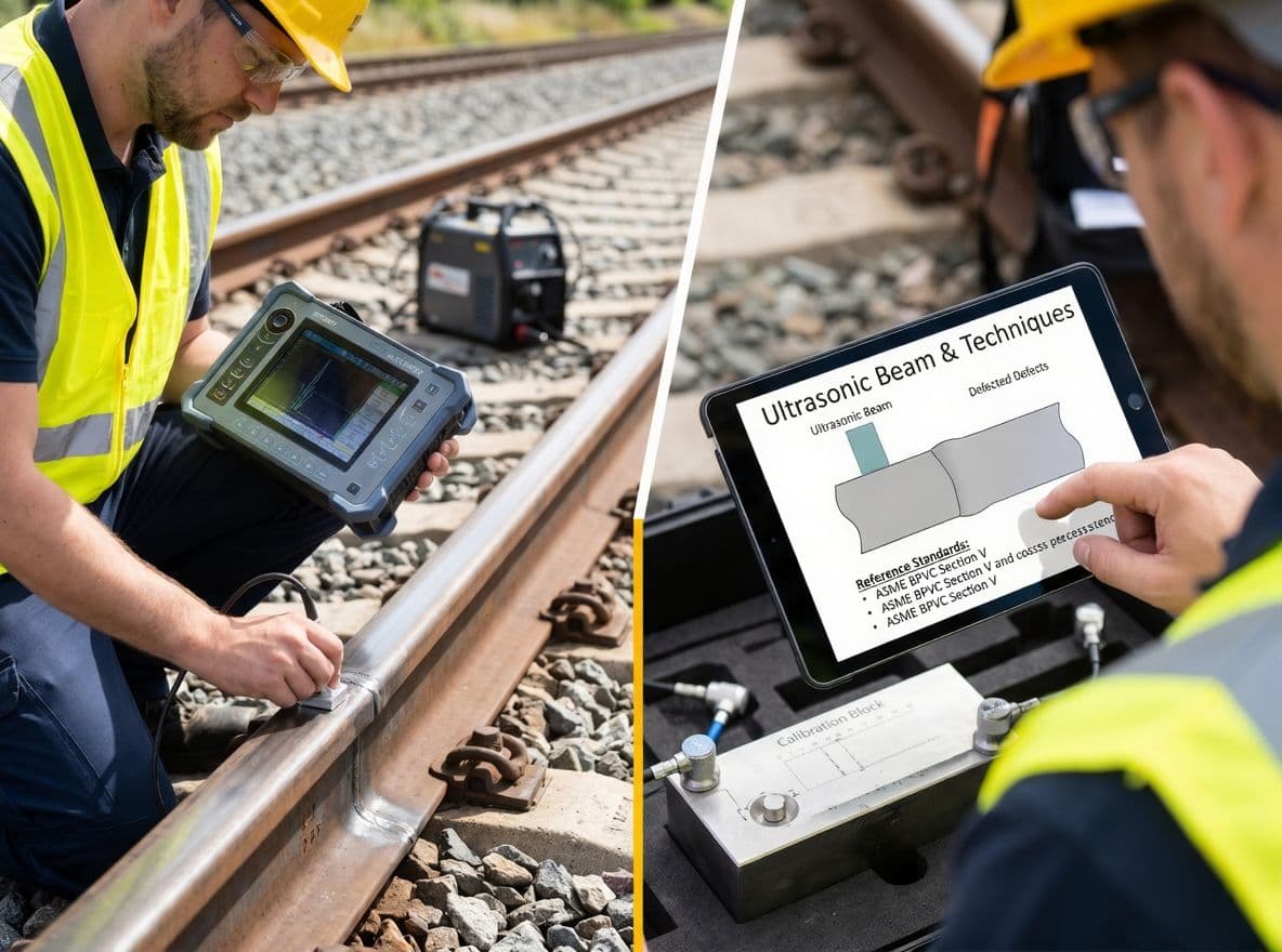
Flash butt weld inspection is the visual, alignment and ultrasonic examination of an electric flash-butt (EFB) rail weld after upset and trim. AWS D15.2/D15.2M:2022 clause 8.11 sets acceptance requirements for flash welded rail joints, with Table 8.2 for UT, and 49 CFR 213.113(d)(6) defines a defective weld in service at 5% of head area.
A flash-butt weld has no filler metal and no casting. The rail ends are heated by flashing and forged together, so its typical flaws are thin and planar, lying in the bond plane at right angles to the rail. That is why the probe plan matters more than the instrument.
This guide covers flash-butt welds only. The thermite weld inspection procedure covers aluminothermic welds zone by zone. The rail weld inspection pillar compares all weld types, and types of rail welding explains how each weld is made.
What does flash butt weld inspection cover?
Flash butt weld inspection covers four field checks on every weld (visual condition of the trimmed upset, alignment, finish and ultrasonic testing) plus the qualification tests that prove the welding procedure. Each check answers a different question, and none of them replaces another.
The field checks accept or reject one weld. The qualification tests (slow bend, hardness, macroetch) prove that a machine, a rail grade and a set of parameters produce sound welds; a slow-bend figure on a weld report says nothing about the weld in front of you.
| Check | When it is done | What it finds | What it can't find |
|---|---|---|---|
| Visual of the trimmed upset | After shearing and again after grinding | Trim tears, shear drag marks, unground flashing, burns, notches at the fillets | Anything in the bond plane |
| Alignment | After the weld cools to ambient | Head vertical and horizontal offset, crown, kink, base offset | Internal quality |
| Finish | After profile grinding | Head finish deviation, low or high spots | Internal quality |
| Ultrasonic testing | After cooling, on clean, blended surfaces | Flat spots, lack of penetration, inclusion clusters, cracks in head, web and base | Very thin oxide films; some volume at the base tips |
| Slow bend, hardness, macroetch | Procedure and operator qualification | Weld strength, ductility, hardness profile, bond structure | Defects in a production weld that wasn't tested |
Key takeaway: report the field checks per weld and the qualification tests per procedure, and keep them in separate records.
How do plant and in-track flash-butt welds differ for inspection?
A plant flash-butt weld is made in a fixed welding line that joins rolled rail into long strings; a mobile (in-track) flash-butt weld is made by a weld head carried on a truck or rail vehicle, usually to join strings or close a gap after a rail change. The process is the same; the inspection conditions are not.
A plant can stop each weld at a fixed inspection station with access to all faces. AREMA's Manual for Railway Engineering covers this work in Chapter 4, Part 3, with section 3.10 on quality assurance of electric-flash butt welding and section 3.11 on fabrication of continuous welded rail (2025 table of contents). In Europe, EN 14587-1:2018 covers flash-butt welding in a fixed plant, including "the welding of rails into welded strings".
A mobile weld is made on rail already in the track, often in the middle of CWR. EN 14587-2:2024, which replaced the 2009 edition in August 2024, covers flash-butt welding "by mobile plant". In North America the same AREMA and AWS documents apply to both.
| Factor | Plant flash-butt weld | Mobile (in-track) flash-butt weld |
|---|---|---|
| Where | Fixed welding line | On the track, at a closure or string joint |
| Main documents | AREMA MRE Ch. 4 Pt 3 sections 3.10 and 3.11; AWS D15.2; EN 14587-1:2018 | AREMA MRE Ch. 4 Pt 3 section 3.10; AWS D15.2; EN 14587-2:2024 |
| Rail consumed | Not a field constraint | Conventional EFB can consume "as much as 1.5 inches" of rail (TTCI TD-06-008) |
| CWR effect | Strings laid later, with their own installation record | Rail must be free to move while the weld is made, and the neutral temperature must be restored |
| Access for UT | All faces, at a fixed station | Ties, anchors, plates and ballast limit probe positions on the base |
| Records | Plant weld log tied to the string | Weld log plus the CWR record of rail temperature and location |
TTCI noted that "the rail must be unconstrained away from the weld to allow rail movement during welding" for closure welds in CWR (TD-06-008, April 2006). A reduced-consumption EFB process in that study used about 0.75 in. of rail, roughly half the conventional amount. So the closure weld record has to show how rail length and temperature were handled, not only the UT result.
Key takeaway: a mobile weld is inspected in worse access conditions and carries a CWR record that a plant weld does not.
What defects form in flash-butt rail welds?
Flash-butt weld defects are mostly planar flaws in the bond plane: flat spots (cold welds or lack of penetration), non-metallic films and inclusion clusters that were not squeezed out at upset, and cracks started by the upset and trim. Porosity and slag, the classic arc and thermite defects, are not the main concern in a forge weld.
The Paton Electric Welding Institute studied fractured high-strength rail flash-butt welds in 2013 and grouped the defects in three families. First, lack of penetration, which forms when the rail end metal is solid or only partly molten before upsetting. Second, iron-manganese silicates not expelled at upset. Third, clusters of aluminum silicate inclusions, which the authors call "dead spots" (Kuchuk-Yatsenko et al., The Paton Welding Journal, 2013, No. 9). Other papers call similar features "matt" or "dull" spots.
| Defect | How it forms | Where it sits | How it shows | Main detection |
|---|---|---|---|---|
| Flat spot, cold weld, lack of penetration (some specifications say "cold lap") | Too little heat at the rail ends before upset; melt solidifies before forging | Bond plane, any part of the section | Flat, featureless area on a fracture face | UT aimed along the rail at the bond plane; bend test at qualification |
| Iron-manganese silicate film | Oxide and silicate layer not expelled with the flash | Bond plane | Smooth, dull area on the fracture | UT; fracture and bend tests |
| Dead or dull spots (aluminum silicate clusters) | Uneven non-metallic inclusions in the parent rail | Bond plane | Small dark patches on the fracture | Often too thin for UT; found on fracture faces |
| Microcracks in the near-contact layer | Low-melting sulfide eutectics at high heat input (Paton, 2016) | Next to the bond plane | Fine cracks on macro sections | UT when large; macro and micro sections |
| Upset and trim damage | Shear drag, tears or undercut when the upset collar is removed | Head-web and web-base fillets, base edges | Notches, tears, sharp corners | Visual first; UT signals from the trimmed profile |
| Horizontal web crack | Tensile residual stress acting vertically in the web (RDSO manual, 2022) | Web, running toward head or base | Lengthwise crack in the web | 0° probe; web-side angle probes |
| Misalignment | Clamping or alignment error in the welder | Head and base | Offset or kink | Straightedge, not UT |
The upset and trim problem has a long record. An AREA rolling-load study published in 1968 traced failures in heavier rail to the head-web fillet, attributed to "shear drag" from removing the weld upset. The same study found that electric flash welds with the upset left on the web failed in the fillets between the web and the upset metal (AREA Bulletin 69, Bulletin 612). TWI gives the general rule for flash removal: check that trimming does not "introduce cracks or tears in the surface of the weld".
A Chalmers fatigue study summarized the picture in one line: defects in flash-butt welds "are almost always confined to iron oxide inclusions in the fusion zone, internal imperfections in the weld or microstructural alterations from post weld trimming" (Ringsberg, Josefson and Skyttebol, ICF11, 2005).
TTCI reported that "Electric flash-butt welds (EFB) fail at a lower rate than thermite welds" (TD-06-008). That is a failure rate, not proof that any single weld is sound.
Key takeaway: look for flat, transverse flaws in the bond plane and for trim damage at the fillets; porosity is the wrong mental model for a forge weld.
What do AWS D15.2:2022 and AREMA MRE Chapter 4 Part 3 require?
AWS D15.2/D15.2M:2022 is a specification with mandatory language that covers flash welding procedure qualification, operator qualification, inspection and acceptance; AREMA MRE Chapter 4 Part 3 holds the recommended-practice specification for quality assurance of electric-flash butt welding. Neither applies on its own. Each one binds only when the owner's specification or the contract invokes it.
AWS D15.2:2022: the flash-welding clauses
The 4th edition of D15.2 changed the document from a recommended practice to a specification. Its foreword says the standard "now includes mandatory language" for welding rails and related components. The public preview gives the structure, and the clause and table numbers below are taken from it. The requirements themselves are paywalled.
| Item in D15.2:2022 | What it covers (title from the preview) |
|---|---|
| Clause 4.5 | Joining of rails by flash welding (FW) |
| Clause 6.2 and Table 6.3 | FW procedure qualification; PQR essential-variable changes that require WPS requalification for flash welds |
| Table 6.7 | Testing requirements for FW qualification |
| Clause 6.3 and Table 6.8 | Slow bend testing and acceptance; slow bend requirements for thermite and flash welds |
| Figures 6.2, 6.3 and 6.4 | Location and spacing of FW hardness indents; FW macroetch test sample; slow bend test configuration |
| Clause 7.13 | Welding operator qualification for flash welding |
| Clauses 8.1 to 8.7 | Inspection responsibility, designated inspector qualifications, inspection of welding, verification of NDT results, repair welds and documentation |
| Clause 8.11 | Inspection procedures and acceptance requirements for flash welded (FW) rail joints |
| Clauses 8.12 and 8.13 | Weld alignment and rail head finish inspection procedures for thermite and flash welds |
| Tables 8.1 to 8.4 | 8.1 visual inspection discontinuity allowances; 8.2 ultrasonic inspection acceptance requirements; 8.3 alignment tolerances; 8.4 finish deviation tolerances |
| Annex C (informative) | Flash welding guidance |
| Forms D-1 and D-2 | Typical procedure qualification and welder performance qualification test records |
Clause numbers and table numbers in D15.2 run separately. Clause 8.2 is Designated Inspectors Qualifications, while Table 8.2 is the UT acceptance table. A weld report that cites "8.2" should say which one it means.
The preview lists no MT or PT acceptance table for rail welds. Whether the body text calls for MT on the trimmed fillets is not public, so check the full standard before writing it into a procedure.
AREMA MRE Chapter 4 Part 3: joining of rail
AREMA's Chapter 4 (Rail) Part 3, Joining of Rail, includes section 3.10, Specification for the Quality Assurance of Electric-Flash Butt Welding of Rail, a short section of about three pages in the 2025 manual. Section 3.11 covers fabrication of CWR and section 3.12 the inspection and classification of second-hand rail for welding. Part 4 adds recommended UT operator qualifications (4.4), procedures (4.5) and calibration rails (4.6).
The manual's own footnote defines its status. Its material is "RECOMMENDED PRACTICE", which a railway may use "either exactly as presented or with modifications". So an AREMA value applies only as the owner adopts it.
Slow-bend minimums: why the published numbers conflict
The slow-bend test is a qualification test: a welded rail is loaded in bending until it reaches a minimum modulus of rupture and a minimum deflection. D15.2 Table 6.8 gives the current AWS values, which are not public. The AREMA values that appear in public TTCI digests disagree with one another.
| Source | Weld type | Rail | Modulus of rupture | Deflection |
|---|---|---|---|---|
| TTCI TD-06-008 (2006), citing AREMA MRE Ch. 4 Table 4-2-5, 2005 edition | EFB | High strength, 341 BHN min. | 125,000 psi | 0.75 in. |
| TTCI TD-19-010 (2019), citing AREMA MRE Ch. 4 Article 3.10.3.6 | Thermite, tested to the EFB article | Over 341 BHN | 120,000 psi | 0.60 in. |
| TTCI TD-13-029 (2013), citing AREMA | Thermite | High strength | Not stated | 0.6 in. |
| AWS D15.2:2022 Table 6.8 | Thermite and flash | By grade | Paywalled | Paywalled |
The differences come from edition changes and from the weld type each report tested. Use none of them as a current limit; take the values from the edition your contract cites, and record it on the PQR.
Key takeaway: cite D15.2 by clause and table with its edition year, and treat every published slow-bend figure as historical until it is checked against the current text.
What do FRA rules say about flash-butt welds?
FRA rules judge a flash-butt weld only once it is in service: 49 CFR 213.113 defines a defective weld, 213.237 tests it as part of the rail, and 213.119 governs in-track welding in CWR. FRA sets no welding procedure, operator qualification or new-weld acceptance criteria.
The defective-weld definition covers plant and field welds alike:
"Defective weld means a field or plant weld containing any discontinuities or pockets, exceeding 5 percent of the rail head area individually or 10 percent in the aggregate, oriented in or near the transverse plane, due to incomplete penetration of the weld metal between the rail ends, lack of fusion between weld and rail end metal, entrainment of slag or sand, under-bead or shrinkage cracking, or fatigue cracking." — 49 CFR 213.113(d)(6)
The rule adds that weld defects "may originate in the rail head, web, or base", and a defect that runs lengthwise through the weld is treated as a split web for remedial action. Lack of fusion at a flat spot is exactly the "lack of fusion between weld and rail end metal" the rule names.
Welds in track are tested with the rail under 49 CFR 213.237, but the rule names no method and covers Class 3–5 track on the routes it lists. FRA's 2014 rule preamble describes rail UT as scanning "the entire rail head and web, as well as the portion of the base directly beneath the web". It also lists "weld upset/finish" among the reflectors an operator must interpret. The base flanges of a flash-butt weld are mostly outside routine rail testing.
For in-track welds, 49 CFR 213.119(d) requires CWR procedures that address the rail installation temperature range during "in-track welding". The records rule, 213.119(j), requires rail temperature, location and date of CWR installations, kept at least one year.
Key takeaway: 213.113 judges a weld in service; the AWS or AREMA specification invoked by the owner judges it when it is made.
How is a flash-butt weld ultrasonically tested?
A flash-butt weld is tested with pulse-echo contact probes aimed along the rail at the bond plane: a 0° probe and 70° probes on the head, angle probes or a 45° pitch-catch pair for the rest of the head, and 70° (with 45° where specified) probes into the web and on top of each base flange. Each zone is scanned from both sides of the weld, and every indication is plotted to the weld line before it is called.
Why the beam angle matters for a flat spot
A flat spot lies in a vertical plane across the rail. A 70° beam travelling along the rail meets that plane 20° off its normal, so a good part of the reflection returns toward the probe. A single 45° beam meets it 45° off normal, and most of the energy reflects downward, away from the probe. That is why some procedures add a pitch-catch (tandem) arrangement, where a second probe receives the reflected beam, for planar flaws in the bond plane.
A published probe plan
Few rail owners publish their weld UT procedure. One that is public is Indian Railways' Manual for Ultrasonic Testing of Rails and Welds (RDSO, revised 2022), chapter 9, on flash-butt and gas pressure welds. It uses 2 MHz shear-wave probes: two 45° probes as a transmitter-receiver pair on the side faces of the head, and a 70° probe for the web and the base flange. It sets sensitivity on a 500 mm standard rail piece with a 5 mm drilled hole, at 60% of full screen height. It requires the upset to be trimmed so it "merge[s] smoothly" into the rail, with scanning surfaces clean for 200 mm each side. That is one railway's procedure under its own rules, shown here as a worked model, not as a US requirement.
The table combines that model with common North American practice for rail welds. Your written procedure governs the final angles.
| Zone | Probe position | Typical angle | What it looks for |
|---|---|---|---|
| Head, vertical | Running surface over the weld | 0° | Horizontal flaws; loss of back-wall echo over the weld |
| Head, transverse | Running surface each side, moving toward the weld | 70° shear | Flat spots and transverse cracks in the head |
| Head, full width | Side faces of the head, pitch-catch pair | 45° + 45° | Planar bond-plane flaws across the head width |
| Web | Web face, about 4 in. (100 mm) back, zigzag toward the weld | 70° (45° where specified) | Bond-plane flaws in the web; trim damage at the fillets |
| Web, horizontal | Running surface | 0° | Horizontal web cracks |
| Base flanges | Top of each flange, gauge and field side, from about 7 in. (180 mm) | 70° shear | Bond-plane flaws and cracks at the base, including near the tips |
| Trimmed upset | Not a scan surface | — | Visual and, where specified, MT |
Calibration and plant practice
Range is set on a standard block; sensitivity is set on reference rail of the same section, because a flat block can't reproduce the beam paths through the head and fillets. See ultrasonic calibration for rail inspection for reference rails.
Plants increasingly use phased array (PAUT) for flash-butt welds. The RDSO manual now requires PAUT testing for "All Flash Butt Welds made in stationary Flash Butt Welding Plants" and prefers it for mobile welds. TTCI's PAUT prototype showed that a healthy EFB weld gives a geometry echo in the lower head fillet, and that "un-ground flashing" can cause reflections that "must be distinguished from true defects" (TD-16-050, 2016). The PAUT vs TOFD for rail weld inspection article explains why TOFD is not a rail weld practice.
Key takeaway: aim the beam at the bond plane from both sides, and set sensitivity on rail of the same section, not on a flat block.
Worked example: a head reflector and a closure-weld record
This example follows one in-track flash-butt closure weld in 136RE rail from a head indication to its plot, then shows why the closure needs a CWR record. The rail dimensions and the arithmetic are real; the indication and the acceptance rule are illustrative.
Inputs. 136RE rail: height 7-5/16 in. (7.3125 in.), head depth 1-15/16 in. (1.9375 in.), base thickness 1-3/16 in. (1.1875 in.), so the web runs from 1.9375 in. to 6.125 in. below the running surface. Shear velocity 0.1280 in./µs (about 3,250 m/s); longitudinal velocity 0.2320 in./µs. Times are round trip, with the wedge delay zeroed. Rail thermal expansion 6.5 × 10⁻⁶ per °F.
Step 1: 0° check. The base echo should arrive at 7.3125 × 2 ÷ 0.2320 = 63.04 µs. It stays steady across the weld. A second, weaker echo at 31.0 µs would place a horizontal reflector at 31.0 × 0.2320 ÷ 2 = 3.596 in. deep, inside the web (1.9375 to 6.125 in.); none is seen here.
Step 2: 70° head scan, side A. An indication peaks at 45.68 µs with the probe index 2.80 in. from the weld centerline.
| Quantity | Side A | Side B |
|---|---|---|
| Indication time (round trip) | 45.68 µs | 45.68 µs |
| Sound path (time × 0.1280 ÷ 2) | 2.924 in. | 2.924 in. |
| Depth (× cos 70° = 0.34202) | 1.000 in. | 1.000 in. |
| Surface distance (× sin 70° = 0.93969) | 2.747 in. | 2.747 in. |
| Probe index from weld centerline (measured) | 2.80 in. | 2.70 in. |
| Reflector position | 2.80 − 2.747 = 0.053 in. on side A | 2.747 − 2.70 = 0.047 in. past centerline, on side A |
| Amplitude against reference | +4 dB | +2 dB |
The two plots agree within 0.006 in., at the same 1.000 in. depth. A reflector that plots to the bond line from both sides, inside a 1.9375 in. head, is a bond-plane flaw such as a flat spot, not trim geometry. A trim or flashing echo would plot to the surface profile and from one side only.
Step 3: disposition. Under an illustrative owner rule ("any bond-line indication at or above reference level, confirmed from both sides, rejects the weld"), this weld is rejected and cut out. The real rule comes from the owner's specification, which may adopt D15.2 Table 8.2.
Step 4: the closure record. Suppose the replacement weld is a conventional EFB that consumes 1.5 in. of rail, and the crew closed the gap by pulling an anchored 400 ft (4,800 in.) length instead of adding rail. The rail neutral temperature would rise by 1.5 ÷ (6.5 × 10⁻⁶ × 4,800) = 1.5 ÷ 0.0312 = 48.1 °F. A reduced-consumption weld using 0.75 in. would shift it by 24.0 °F. That is why 213.119(d) asks for in-track welding procedures, and why the weld record should note rail temperature, any rail added, and the length adjusted.
Check: the 1.000 in. depth is less than the 1.9375 in. head depth, the 3.596 in. web depth falls between 1.9375 and 6.125 in., and at 70° the surface distance is tan 70° × depth = 2.7475 × 1.000 = 2.747 in., which matches the table.
Key takeaway: the both-side plot to the bond line, not the amplitude, is what separates a flat spot from trim geometry.
What should a flash-butt weld record contain?
A flash-butt weld record should identify the weld, the procedure and operator, each inspection result with the acceptance document and edition, and, for an in-track weld, the CWR data that 213.119(j) requires. D15.2 has its own documentation clause (8.7) and sample qualification forms (D-1, D-2); the owner's specification sets the field format.
| Record item | Why it is needed | Source of the requirement |
|---|---|---|
| Weld ID, location (milepost or string number), date and rail section, grade and heat | Traceability | Owner specification |
| Plant or mobile, machine ID, WPS and operator | Links the weld to its qualified procedure and operator | D15.2 clauses 6.2 and 7.13 (as invoked) |
| Machine parameter log (flashing, upset, time) | Shows the weld ran inside the qualified window | Owner specification; D15.2 Table 6.3 variables |
| Visual, alignment and finish results | Separate accept/reject for each check | D15.2 Tables 8.1, 8.3 and 8.4 (as invoked) |
| UT procedure, probes, reference rail, reference gain, results by zone | Makes the UT repeatable and auditable | Owner specification; D15.2 8.11 and Table 8.2 (as invoked) |
| Acceptance document and edition | A weld can't be "accepted" without one | Contract |
| Rail temperature, location and date of the CWR installation | Required for CWR | 49 CFR 213.119(j)(1), kept at least 1 year |
If the same weld is later found defective during a rail test, that finding goes on the 213.237 inspection record. Under 49 CFR 213.241(c), that record gives the date, the track tested, the location, type and size of each defect, and the initial remedial action. It is kept at least two years after the inspection and one year after the remedial action (213.241(d)).
Key takeaway: one weld can need three records: the plant or field weld log, the CWR record, and, if it fails later, the rail test record.
What flash butt weld inspection can't do
Flash butt weld inspection reduces the risk of a bad weld entering service, but it can't prove that the bond plane is fully fused.
- Thin films reflect almost nothing. The Paton group reported that the "small thickness" of dead spots impedes their detection by UT. In a 2016 study, the same institute wrote that very thin films are "problematic" to detect with UT. Small dead spots are tolerated in Ukrainian practice up to 15 mm² total; that limit is national and doesn't transfer to US specifications.
- Detection is good only above a size. The 2013 paper says lack of penetration as small as 1–2 mm² is detected "using modern means of ultrasonic testing", but that figure comes from one institute's systems and settings. It is not a probability of detection.
- Tight planar flaws depend on angle. A flat spot held closed by compression, or tilted off the transverse plane, can return a weak echo to a single probe. Pitch-catch arrangements help but add setup time.
- Trim geometry mimics defects. Unground flashing and the trimmed upset return echoes (TD-16-050). Both-side plotting separates most of them, but not all.
- The base tips are hard to reach. Rail test cars don't cover most of the base, and in track the ties, plates and anchors limit where a base-flange probe can sit.
- Acceptance isn't universal. D15.2 Table 8.2 and the AREMA section 3.10 values are paywalled and owner-adopted, so one owner's reject can be another's accept.
"Small thickness impedes their detection during ultrasonic testing." — Kuchuk-Yatsenko et al., on dead spots in flash-butt rail welds, The Paton Welding Journal (2013)
That is why plants rely on machine parameter monitoring as well as UT: a weld made outside the qualified flashing and upset window is suspect even when its scan is clean.
How EMA Industries applies this
EMA Industries provides rail weld inspection for transit agencies, short lines and industrial track owners, including visual, alignment and finish checks and hand UT of flash-butt welds by zone, with the head, web and both base flanges scanned from each side. Weld reports should name the acceptance document and edition used. EMA is based in Southern California and mobilizes nationwide. For flash-butt weld UT or a review of a rail weld inspection procedure, see ultrasonic examination services or contact EMA Industries.
Related reading: Thermite weld inspection procedure · Rail weld inspection pillar · Types of rail welding · Continuous welded rail · 49 CFR 213.237 rail flaw inspection · Detecting rail defects
Frequently asked questions
What is the most common defect in a flash-butt rail weld?
Lack of fusion in the bond plane, usually called a flat spot, cold weld or lack of penetration. It forms when the rail ends are too cool or the melt solidifies before upset. Oxide and silicate films that are not squeezed out at upset are the next most common. Both lie across the rail, so the beam has to be aimed along the rail at the weld line.
Which probe angles are used to test a flash-butt weld?
Typically a 0° probe and 70° probes on the head, 70° (sometimes with 45°) into the web, and 70° on top of each base flange, each scanned from both sides. Some procedures add a pair of 45° probes working as transmitter and receiver to catch planar flaws across the head. Your written procedure sets the final angles and the reference rail.
Does AWS D1.1 apply to flash-butt rail welds?
No. AWS D1.1 is the structural steel code. Flash-butt rail welds are accepted to the owner's specification, which in the US often invokes AWS D15.2/D15.2M:2022 (clause 8.11, with Table 8.2 for UT) and AREMA MRE Chapter 4 Part 3 section 3.10. ASME Section V describes UT methods but sets no acceptance criteria.
Are mobile flash-butt welds inspected differently from plant welds?
The UT technique is the same, but the conditions differ. A mobile weld is tested in track, where ties, plates and anchors limit probe positions on the base, and it needs a CWR record of rail temperature and location under 213.119(j). A plant weld is tested at a fixed station with full access, and its record ties to the rail string.
When is a flash-butt weld defective under FRA rules?
Under 49 CFR 213.113(d)(6), a plant or field weld in service is defective when transverse discontinuities exceed 5% of the rail head area individually or 10% in aggregate. Lack of fusion and fatigue cracking are among the named causes. The owner then verifies the indication and applies the remedial action for its size.
Sources
- AWS D15.2/D15.2M:2022, Specification for Joining Railroad Rail and Related Rail Components, public preview (title page, foreword, scope, contents, lists of tables and figures), American Welding Society
- AREMA Manual for Railway Engineering, Chapter 4 (Rail) table of contents, 2025, AREMA
- 49 CFR 213.113, Defective rails, eCFR (text read on Cornell LII, October 2026)
- 49 CFR 213.119, CWR plan contents, eCFR (text read on Cornell LII, October 2026)
- 49 CFR 213.237, Inspection of rail, eCFR
- 49 CFR 213.241, Inspection records, eCFR (text read on Cornell LII, October 2026)
- FRA, Track Safety Standards; Improving Rail Integrity, final rule, 79 FR 4234 (January 24, 2014), Federal Register
- Kristan, LoPresti and Garcia, Initial Results of Robotic Slot Weld and Reduced Consumption EFB Weld Testing at FAST, TD-06-008 (April 2006), TTCI/MxV Rail
- TTCI, phased array rail inspection prototype results, TD-16-050 (November 2016), TTCI/MxV Rail
- Brice, Full Section, High Hardness Thermite Welds, TD-19-010 (July 2019), TTCI/MxV Rail
- TTCI, thermite welds in high-strength rail, TD-13-029 (November 2013), TTCI/MxV Rail
- Kuchuk-Yatsenko, Shvets, Didkovsky, Antipin and Kapitanchuk, "Defects of joints of high-strength rails produced using flash-butt welding", The Paton Welding Journal, 2013, No. 9
- Kuchuk-Yatsenko, Shvets, Didkovsky and Antipin, "Effect of non-metallic inclusions of rail steel on welded joint formation", The Paton Welding Journal, 2016, No. 5–6
- AREA, "Results of Rolling-Load and Slow-Bend Tests of Butt Welded Rail Joints", AREA Bulletin 69, Bulletin 612 (1968), TRID abstract
- Ringsberg, Josefson and Skyttebol, "Fatigue crack growth in welded rails", ICF11 (2005)
- TWI, "Should I remove the flash from a flash butt weld?"
- RDSO, Manual for Ultrasonic Testing of Rails and Welds, revised 2022 (incorporating ACS-2), Indian Railways (copy hosted by DFCCIL)
- EN 14587-1:2018, flash butt welding of new rails in a fixed plant, Genorma listing
- EN 14587-2:2024, flash butt welding of new rails by mobile plant, Genorma listing