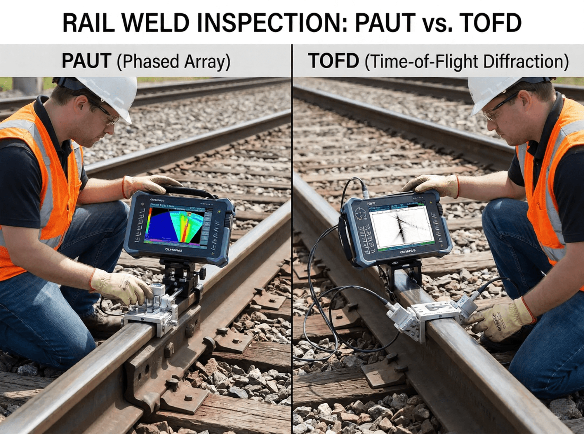
PAUT vs TOFD on rail welds is not an even contest. TOFD needs a probe pair straddling the weld on parallel surfaces, and ISO 10863 scopes it to welded joints "of simple geometry in plates, pipes, and vessels", which a rail head, web and foot are not. PAUT can steer around rail geometry, but on thermite welds it is still mostly research and verification.
That leaves conventional multi-angle ultrasonic testing (UT), with 0°, 37–45° and 70° probes and hand scans of the base, as the working method for rail welds in track. This article explains why, shows where PAUT genuinely helps, and works through how far a phased-array sweep reaches into a thermite weld foot.
How do TOFD and PAUT work?
TOFD and PAUT are both ultrasonic techniques, but TOFD times diffracted signals from flaw tips with a separate transmitter and receiver, while PAUT fires many elements of one probe with electronic delays to steer and focus a pulse-echo beam. The physics difference decides where each can be used.
Time-of-flight diffraction (TOFD)
In TOFD, a transmitting probe and a receiving probe sit on the same surface, facing each other on opposite sides of the weld. A wide-angle longitudinal beam crosses the weld. The receiver sees a lateral wave that travels just under the scanning surface, a back-wall echo from the opposite surface, and, between them, weak signals diffracted from the upper and lower tips of any flaw.
TOFD sizes a flaw from the arrival times of those tip signals, not from echo amplitude. The depth formula is a diffraction geometry, d = √[(ct/2)² − S²], where S is half the probe center spacing. It is not the pulse-echo depth formula. ASTM E2373 states that TOFD "is not based on amplitude response", which is why it gives good through-wall height estimates.
TOFD also detects flaws. The original version of this article said TOFD "focuses more on defect sizing than detection", which is wrong. ASTM E2373 describes TOFD "as a tool for detection and sizing of discontinuities", and ISO 10863 says it can be used as a stand-alone method. TWI notes it can detect "a variety of flaw types, including planar flaws" such as lack of sidewall fusion, and tip diffraction depends less on a favorably angled reflector than pulse-echo does.
Phased array UT (PAUT)
A PAUT probe holds a row of small elements, commonly 16 to 64. The instrument fires them with programmed delays (focal laws) to sweep a beam through a range of angles (a sectorial or S-scan) or to step a fixed-angle beam along the array (a linear or E-scan). It is still pulse-echo UT: the beam must reach the flaw and reflect back to the same probe.
Encoded PAUT records the A-scans along the scan line and displays them as cross-sectional images. That record, and the ability to cover several angles from one probe position, are its practical advantages over a single fixed-angle probe. The probe still has to travel along the weld; "scanning without moving the probe" is a sales phrase, not a description of a weld examination.
Key takeaway: TOFD is a pitch-catch diffraction technique that needs two probes on a shared, regular surface; PAUT is steerable pulse-echo from one probe.
Why is TOFD generally unsuitable for rail welds?
TOFD needs parallel scanning and back-wall surfaces of roughly uniform thickness so the lateral wave and back-wall echo frame a known depth window. A rail section has a crowned head, a narrow web and a tapered foot, so no single TOFD probe pair sees a regular plate through a rail weld. Thermite welds add a cast collar that blocks probe placement close to the weld.
Consider each part of the rail. On a 136RE rail the head is about 2-15/16 in. wide and crowned, the web is about 11/16 in. thick, and the base is 6 in. wide and tapers toward the flange tips (section dimensions from a supplier drawing; confirm against AREMA). A TOFD pair placed on the running surface would look down through the head into the head fillets and web, where the beam scatters off curved surfaces and the "back wall" changes from point to point. There is no stable back-wall signal to calibrate depth.
On the base, the top of the flange slopes and the thickness changes across the width. On the web, the scanning surface is narrow and the probes would need to be very close together. ISO 10863, the international TOFD standard for welds, limits its scope to "full penetration welded joints of simple geometry in plates, pipes, and vessels". A rail weld doesn't meet that description.
Thermite welds are harder still. The thermite process casts molten steel into a mold around a gap between the rail ends; TTCI's TD21-027 gives the gap as "1 to 1.5 inches". The cast collar around the head, web and base is normally left on the web and base after the running surface is ground. TTCI warns that thermite welds "have a variable geometry which generates indications that could be misinterpreted as defects".
Flash-butt welds have no cast collar, and the upset is trimmed, but the rail profile problem remains. Flash welding is also a resistance (pressure) weld, not the fusion weld that ISO 10863 is written for.
We found no published rail weld TOFD procedure, validation study or code acceptance criterion in a search of public sources (October 2026). That doesn't prove nobody has tried it in research. It does mean a buyer shouldn't accept TOFD as a rail weld method without a demonstrated, qualified technique on the actual rail section.
Key takeaway: TOFD's dependence on a regular plate geometry rules it out for rail head, web and foot, and the thermite collar makes field thermite welds the worst case.
Where does TOFD fit, if not on rail?
TOFD belongs on full-penetration butt welds in plate, pipe and pressure vessels, roughly 9 to 300 mm thick, where its depth sizing complements pulse-echo or PAUT. ASTM E2373 says the technique "has proven effective on thicknesses from 9 mm to 300 mm", and that it can "improve sizing estimates" of flaws found by pulse-echo and help tell flaws from geometric reflectors.
Typical TOFD jobs include:
- longitudinal and circumferential seams in pressure vessels and storage tanks
- pipeline and process-piping girth welds, often as one channel of an automated system
- thick structural butt welds where the contract allows UT in place of radiography
- in-service monitoring of a known flaw's through-wall height
The thickness limits differ by source, and the original article's "about 6 mm minimum" needs that context. ISO 10863 sets a 6 mm minimum, ASTM E2373 cites 9 mm as the proven lower limit, and TWI says that even with 10 or 15 MHz probes it is "not recommended for use on thicknesses of less than 13mm". Thinner sections push flaw signals into the lateral wave.
TOFD interpretation is not easy, which the original also got wrong when it said TOFD "requires less interpretation" than imaging methods. TWI states the point directly:
"A high degree of operator skill/experience is required to correctly interpret and report the findings." (TWI, Weld inspection with ultrasonic time-of-flight diffraction)
TOFD also has two dead zones. The near-surface zone sits under the lateral wave, about 4 to 5.5 mm for a 50 mm probe spacing at 5 to 10 MHz in one published estimate. The back-wall zone sits just above the back wall. That's why ISO 10863 and ASTM E2373 both describe TOFD used alongside pulse-echo or PAUT, not as a full-volume method on its own.
What can PAUT do on rail welds?
PAUT can image the weld collar region and base from several angles at one probe position, and research shows full volumetric coverage of a thermite weld is possible with multiple PAUT probes on both sides of the rail. It is not yet a standard field method for rail welds in North America. The best public evidence comes from TTCI (now MxV Rail) research funded by the AAR.
What the research shows
TTCI's TD21-027 (Poudel, September 2021) used CIVA beam simulation to work out PAUT setups for thermite welds at the FAST test track. Its key points:
| TD21-027 finding | Detail |
|---|---|
| Why welds matter | About 88% of FAST rail breaks were thermite weld breaks, and about 95% of those were in the web, web-base fillet and base |
| Current practice | Post-installation flaw detection is "limited to visual inspection", which doesn't reveal internal defects |
| Base | Sectorial shear wave, 45° to 70°; full coverage needs a full skip off the rail base, not the weld, because the weld underside is uneven |
| Web | Sectorial shear wave, 30° to 70°, from the head, with the probe further from the weld |
| Fillets | Fixed 45° shear wave PAUT probe |
| Head | Sectorial longitudinal wave, −45° to +45°, probe turned across the rail |
| Probe | 5 MHz, 32 elements, 0.5 mm pitch did best on the base and web |
| Full kit | Four 32-element base/web probes, two 32-element head/web probes and four 16-element fillet probes: 256 elements, 32 pulsers |
| Signal quality | A good signal-to-noise ratio is "especially challenging to maintain in the weld collar line" |
That is a modeling study recommending a design for a portable scanner. It is not a field trial, a probability-of-detection study or a qualified procedure.
TTCI's TD-16-050 (November 2016) tested a PAUT roller search unit on a test vehicle at up to 20 mph. It found transverse defects under shells, weld defects and web defects, and TTCI reported that it "performed equivalent or better than a conventional UT inspection truck on every type of rail defect tested". But it is "a head contacting inspection technique" and so is "unable to inspect the rail base flanges". It reaches the base only directly under the web.
Where PAUT helps
- Sizing and characterization. Once a test car or hand probe flags a weld, an encoded S-scan shows where the indication sits relative to the collar, fillet and base. That's easier to judge than a single A-scan.
- Imaging the collar and base region. Several angles from one probe position reduce the guesswork about which leg and which surface produced an echo, which matters where the collar geometry creates false indications.
- A record. Stored scans let a Level III review a weld after the crew has left, which conventional hand UT doesn't give.
What limits PAUT on rail welds
- Geometry. The collar, the web-base fillet radius and the tapered foot restrict where a wedge can sit. TD21-027 says probes must be "moved further back, re-oriented, and deployed using a full skip approach" to reach the fillets.
- Coupling. Contoured, as-cast and ground surfaces make constant coupling hard. A wedge that rocks on the flange slope changes the beam angle and drops signal.
- Sizing caution. ASTM E2700, the PAUT weld practice, warns that "extreme caution should be used when attempting to size indications using phased array" because beam spread can oversize them.
- Procedure qualification. No public North American rail weld acceptance standard was found that names PAUT. A PAUT technique has to be written, demonstrated on reference welds with known reflectors, and accepted by the track owner before it carries any weight.
Key takeaway: PAUT is a credible verification and sizing tool on rail welds, and research points to full-volume thermite weld inspection, but it isn't yet routine practice.
How are rail welds actually inspected today?
Rail welds in track are inspected by visual examination and conventional multi-angle UT, with 0°, 37–45° and 70° probes on the test car or hand probes, plus hand angle-beam scans of the base where the test car can't reach. Acceptance comes from the owner's specification, not from the method.
The usual probe set on rail does the following:
| Probe | What it looks for at a weld |
|---|---|
| 0° longitudinal | Horizontal discontinuities and loss of back-wall (base) echo, which flags porosity, shrinkage or lack of fusion in the beam's path |
| 37–45° shear | Defects in the web and the web-base fillet area, and bolt-hole cracks near joints |
| 70° shear | Transverse defects in the head, aimed forward and back along the rail |
| Hand angle-beam on the base | The base flanges either side of the web, which head-contact search units miss |
The base gap is the critical point for thermite welds. TTCI's Thermite Weld Failure Survey (TD-00-013, Kristan, July 2000) found that 40% of 265 reported revenue-service thermite weld failures came from slag or porosity, 56% of those at the web-base fillet. The same survey noted that "the ultrasonic rail flaw detection process only scans the head and web of the rail, and not the majority of the base".
So a field weld program usually adds hand UT of the base and fillets after installation and during follow-up tests. Exact probe angles, frequencies, scan patterns and reference blocks come from the owner's procedure, so the angles in the table are typical rather than mandated. Part 213 names no test method.
For defects found later, FRA's rule defines what counts as a defective weld in service:
"Defective weld means a field or plant weld containing any discontinuities or pockets, exceeding 5 percent of the rail head area individually or 10 percent in the aggregate…" (49 CFR 213.113(d)(6))
The same paragraph says weld defects "may originate in the rail head, web, or base". That's a disposition rule for welds in service, not an acceptance standard for new welds.
PAUT vs TOFD by weld type: which method suits which weld?
On rail, conventional multi-angle UT is the working method and PAUT is a supplement; TOFD fits structural and pipe butt welds, not rail. The table rates each method by weld type, based on the standards and research cited in this article.
| Method | Thermite rail weld | Flash-butt rail weld | Structural CJP butt weld (plate) | Pipe butt / girth weld |
|---|---|---|---|---|
| Conventional multi-angle UT (0°, 37–45°, 70°, hand base scans) | Standard practice. Head and web by test car or hand; base and fillets by hand | Standard practice. Plant welds are trimmed, so coverage is easier than thermite | Standard practice (e.g. AWS D1.1 angle-beam UT) | Common, especially manual UT on smaller diameters |
| PAUT | Research and verification. Full coverage modeled with multiple probes (TD21-027); collar, fillet and coupling limit it | Verification and sizing. Better access than thermite, but still a contoured profile; procedure must be qualified | Suitable. ASTM E2700 covers butt and tee welds 9–200 mm; D1.1 has a PAUT annex (confirm the edition) | Suitable. Widely used, often encoded or in automated systems |
| TOFD | Generally unsuitable. No parallel surfaces, collar blocks probe placement | Generally unsuitable. Rail profile, and not a fusion weld | Suitable for thick sections (about 9–300 mm), paired with pulse-echo or PAUT for the dead zones | Suitable, commonly as a channel in automated systems alongside PAUT zones |
| Radiography | Used historically and in some countries; access and radiation control limit it in track | Rarely used in track | Common, often the method UT replaces | Common |
Every "suitable" rating still depends on a written procedure accepted by the owner or the governing code. A suitable method used without a qualified procedure doesn't produce an acceptable examination.
Worked example: PAUT coverage of a thermite weld foot
From a probe placed 40 mm from the weld center on the base flange, a 45°–70° sectorial sweep reaches only the lower half of the near fusion face on the direct leg, and only beams up to about 45° can use a full skip off the rail. The example shows why TD21-027 calls for probes on both sides of the rail, and why the weld toe at the top of the foot is the hardest zone.
This is a simplified two-dimensional ray check, not a beam model. It ignores beam spread, which widens real coverage, and it treats the flange as a flat plate. The inputs are illustrative and must be replaced with the actual rail section and weld kit dimensions before use.
Inputs
| Input | Value | Basis |
|---|---|---|
| Local base thickness under the probe, t | 20 mm | Illustrative; the 136RE base is 1-3/16 in. (30 mm) at the center and thinner toward the tips. Confirm on the drawing |
| Weld gap (fusion faces at ±12.5 mm from weld center) | 25 mm | Chen et al. (2006) standard gap; TD21-027 gives 1–1.5 in. |
| Collar half-width on the base surfaces | 19.7 mm | Half of the 39.4 mm collar in Chen et al. (2006) |
| Probe index offset from weld center, X | 40 mm | TD21-027 base probe position |
| Sweep | 45° to 70° shear | TD21-027 base setting |
Method
- Direct (first) leg: a ray at angle θ reaches depth d = h / tan θ at horizontal distance h from the index point. The near fusion face is at h = 40 − 12.5 = 27.5 mm, and the far face at h = 52.5 mm.
- Full skip: the beam bounces off the underside of the base at h = t × tan θ. That bounce must land on rail, before the collar starts at 40 − 19.7 = 20.3 mm, so tan θ ≤ 20.3 / 20 = 1.015, which gives θ ≤ 45.4°.
Results (t = 20 mm, X = 40 mm)
| Angle | tan θ | Bounce point h (mm) | Direct-leg depth at near face (mm) | Direct-leg depth at far face (mm) | Full skip on rail? |
|---|---|---|---|---|---|
| 45° | 1.000 | 20.0 | 27.5 > t: hits the base underside first | 52.5 > t | Yes; second leg crosses the near face at 12.5 mm depth and reaches the top surface at the weld center |
| 50° | 1.192 | 23.8 | 23.1 > t: hits the base underside first | 44.1 > t | No, bounce under the collar |
| 55° | 1.428 | 28.6 | 19.3 | 36.8 > t | No |
| 60° | 1.732 | 34.6 | 15.9 | 30.3 > t | No |
| 65° | 2.145 | 42.9 | 12.8 | 24.5 > t | No |
| 70° | 2.747 | 54.9 | 10.0 | 19.1 | No |
What the numbers say
- On the direct leg, angles from about 54° (tan⁻¹ 27.5/20) to 70° cover the near fusion face from 20 mm deep up to 10.0 mm deep. Every depth stays within the 20 mm thickness.
- The top 10 mm of the near face, the weld toe on the foot, isn't reached by the direct leg. The 45° full skip crosses the face at one depth only, 12.5 mm, so it doesn't fill that band.
- The far fusion face is reached directly only by the 70° ray, near the bottom (19.1 mm). The far half of the weld needs a probe on the other side of the weld.
- Moving the probe further back makes the direct leg worse (the near face gets deeper for each angle). Moving it closer is limited by the collar and the wedge. At t = 25 mm, the full-skip limit drops to about 39°, below the sweep.
The conclusion matches TD21-027's recommendation of several probes on both sides of the rail, although TTCI's model, with real geometry and beam spread, found 45°–70° sufficient. The weld toe on top of the foot is where Chen et al. found cold laps "at weld toes in the rail base", so it's the zone a procedure should prove coverage for on a reference weld. That's a job for a Level III with the actual rail section, collar and wedge dimensions.
Which standards govern rail weld UT?
Rail welds in track are governed by the track owner's specifications, with AWS D15.2:2022 and AREMA MRE Chapter 4, Part 3 as the North American references and EN 14730 and EN 16729 in Europe. AWS D1.1 and EN 15085 are not rail weld standards. The original article cited both of those; they're corrected here.
| Document | What it covers for rail welds | Status of PAUT and TOFD |
|---|---|---|
| AWS D15.2/D15.2M:2022, Specification for Joining Railroad Rail and Related Rail Components | Joining, repair, maintenance and inspection of rail welds, including thermite (TW) and flash (FW) welds. The 2022 edition changed it from a recommended practice to a specification. Its table of contents lists TW and FW acceptance clauses and a UT acceptance table | Not confirmed; the clause text is paywalled. Check the edition named in your contract |
| AREMA MRE Chapter 4, Part 3, Joining of Rail | Includes specifications for the quality assurance of electric flash-butt welding and, in the 2025 edition, of thermite welding of rail | Recommended practice; content paywalled. AREMA is not a regulator |
| Track owner and transit agency specifications | The actual acceptance criteria, inspection timing, probe sets and inspector qualifications | Whatever the owner writes; this is where a PAUT technique would have to be approved |
| EN 14730-1:2017 and EN 14730-2 | Part 1: laboratory approval of aluminothermic welding processes. Part 2: approval of welders, contractors and the acceptance of final welds by approved inspectors | European; acceptance tests per the infrastructure manager |
| EN 16729-5:2023 | Visual and ultrasonic testing of rail welds in track, for EN 13674-1 profiles; it doesn't define how many welds to test | European in-track standard |
| 49 CFR 213.113(d)(6) | FRA definition and remedial action for defective welds in service | Names no method; Part 213 doesn't mention ultrasonic testing |
AWS D1.1 is the structural steel welding code. It is correct for building and bridge-type structural welds, not for rail joined in track. EN 15085 covers welding of railway vehicles and components, not track. Technique documents such as ASTM E2700 (PAUT), ASTM E2373 (TOFD) and ISO 10863 (TOFD) say how to examine a weld; none of them sets rail weld acceptance.
What can't PAUT and TOFD do on rail welds?
Neither method gives a complete, qualified rail weld examination on its own today: TOFD can't cope with rail geometry, and PAUT is limited by collar access, coupling and the lack of a qualified rail weld procedure. These limits apply whatever the instrument's specifications say.
- TOFD on rail: no parallel surfaces, no stable back-wall reference, the collar blocks probe placement on thermite welds, and two dead zones still need a pulse-echo supplement.
- PAUT on thermite welds: full coverage needs several probes on both sides and full-skip paths that must bounce on rail, not weld. The weld toe on the foot is hard to reach, and collar geometry generates indications that look like defects.
- Head-contact PAUT on test cars: it doesn't inspect the base flanges (TD-16-050), so it doesn't close the base gap that hand UT covers.
- Sizing: PAUT amplitude-based sizing can oversize indications (ASTM E2700 1.2.1). TOFD sizes well by tip timing but only in the geometry it was set up for.
- Acceptance: no technique supplies its own accept or reject criteria. Those come from the owner specification, D15.2 or the European standards above.
- Interpretation: both methods need trained, qualified analysts. Imaging doesn't remove judgment, and TOFD in particular demands experience.
How EMA Industries applies this
EMA Industries performs rail weld inspection and ultrasonic rail flaw testing for transit agencies, short lines and industrial track owners, working from Southern California and mobilizing nationwide. For thermite and flash-butt welds we use conventional multi-angle UT with hand scans of the base and fillets, to the owner's specification, and our NDT Level III services cover writing and reviewing the procedure. For structural CJP welds under AWS D1.1, the UT, MT and PT methods apply instead. See our ultrasonic examination services or contact EMA Industries to discuss a weld inspection scope.
Related reading
- The importance of rail welding in modern railroads, our rail weld inspection overview
- Aluminothermic weld inspection
- What's the difference between UT and PAUT?
- Automated ultrasonic systems
Frequently asked questions
Can TOFD be used to inspect thermite rail welds?
In general, no. TOFD needs a probe pair on a regular surface with a parallel back wall, and a thermite weld has a curved head, a narrow web, a tapered foot and a cast collar. We found no published rail weld TOFD procedure or acceptance criterion, so any proposal to use it needs a demonstrated technique on the actual rail section.
Is PAUT approved for rail weld inspection?
Approval sits with the track owner, not with the method. AWS D15.2:2022 and AREMA MRE Chapter 4 set the North American framework, but we couldn't confirm from public text whether either names PAUT. A PAUT technique becomes acceptable when the owner accepts a written procedure demonstrated on reference welds.
What probe angles are used to test rail welds?
Typically a 0° longitudinal probe, a 37–45° shear probe and a 70° shear probe, on the test car or by hand. Because head-contact search units miss most of the base, field welds also get hand angle-beam scans of the base and the web-base fillet. Exact angles come from the owner's procedure.
Where does TOFD work best?
TOFD works best on full-penetration butt welds in plate, pipe and pressure vessels, roughly 9 to 300 mm thick, as ASTM E2373 describes. It is usually paired with pulse-echo or PAUT to cover its near-surface and back-wall dead zones. A trained analyst is essential, because TOFD images are hard to interpret.
Why do thermite welds need hand UT of the base?
Test cars scan the head and web but "not the majority of the base", according to TTCI's 2000 thermite weld failure survey. That matters because most thermite weld failures start in the web, the web-base fillet and the base. Hand scans of the base close the gap the test car leaves.
Sources
- 49 CFR 213.113, Defective rails, eCFR (text checked on Cornell LII, October 2026)
- Poudel, A., Phased Array Ultrasonic Beam Modeling for Rail Thermite Welds, TTCI Technology Digest TD21-027, September 2021
- Witte, M., Poudel, A., Characterizing Rail Flaws Using Phased Array Ultrasound, TTCI Technology Digest TD-16-050, November 2016
- Kristan, J., Thermite Weld Failure Survey, TTCI Technology Digest TD-00-013, July 2000
- Chen, Y., Lawrence, F.V., Barkan, C.P.L., Dantzig, J.A., Weld Defect Formation in Rail Thermite Welds, Proc. IMechE Part F, 220(4), 2006
- ASTM E2373/E2373M-19(2024), Standard Practice for Use of the Ultrasonic Time of Flight Diffraction (TOFD) Technique, ASTM store page
- ASTM E2700-26, Contact Ultrasonic Testing of Welds Using Phased Arrays, ASTM store page
- EN ISO 10863:2020, Use of time-of-flight diffraction technique (TOFD), scope listing
- TWI, Weld inspection with ultrasonic time-of-flight diffraction, FAQ
- AWS D15.2/D15.2M:2022 public preview, American Welding Society
- AREMA MRE Chapter 4 table of contents (2025), AREMA
- EN 14730-1:2017 scope listing
- EN 14730-2:2021 and EN 16729-5:2023, scopes from national standards catalog listings