Automated ultrasonic systems are UT setups in which a scanner moves the probes, an encoder records where each signal came from, and every A-scan is stored for later review. Codes accept them by name: ASTM E1961 covers zonal AUT of pipeline girth welds, and 49 CFR 213.240 governs continuous ultrasonic rail testing.
The gain is evidence and repeatability, not a guaranteed detection rate. What automation doesn't change is the physics, or the need for a qualified person to set the system up, prove it on a reference block and interpret the data. This guide covers what makes UT "automated", where codes recognize it, a worked scan-time and coverage example, how rail test cars fit the picture, and what automated ultrasonic systems can't do.
What makes ultrasonic testing "automated"?
Ultrasonic testing becomes automated when probe position is controlled or encoded and the full data set is stored, so that the examination can be reviewed and repeated without the original operator present. A flaw detector on a motorized cart is not automated UT if nothing records where each signal came from.
Four features separate a true automated ultrasonic system from a manual scan:
- An encoded scanner. A motorized or manually pushed scanner carries the probes along a band, track or rail, and a wheel or optical encoder logs the position of every firing. ASTM, ASME and ISO documents use "mechanized" for scanners moved by machine, "semi-automated" for encoded scanners moved by hand, and "automated" for systems where both movement and recording are machine-controlled. Check which term your contract uses, because the code requirements can differ.
- Full data storage. The system keeps every A-scan, not just the indications the operator chose to note. That stored file is what lets a second analyst, an owner's Level III or an auditor re-evaluate the weld later.
- A defined examination volume. In pipeline AUT, the weld is split into thin height bands ("zones"), each assigned to its own probe or focal law. In phased array (PAUT) and time-of-flight diffraction (TOFD), a scan plan shows which beams cover which part of the weld.
- A calibrated, demonstrated setup. The configuration is proven on a reference block with known reflectors before production scanning, and rechecked at set intervals.
| Component | What it does | What to check in a procedure |
|---|---|---|
| Scanner and guide (band, track, rail carriage) | Holds probe offset and angle constant along the weld | Offset from the weld centerline, wedge contact, guide alignment |
| Position encoder | Tags every A-scan with a scan-axis position | Encoder calibration over a known distance; allowed data dropout |
| Multi-channel instrument or PAUT unit | Fires probes or focal laws and digitizes the signals | Channel count, gain settings, recording increment |
| Probes and wedges | Generate the beams for each zone or angle range | Frequency, element count and pitch, wedge curvature for pipe |
| Acquisition and analysis software | Stores the data and builds B-, C-, D- and S-scan views | File format, review tools, how indications are sized |
| Reference block | Proves the setup detects and places known reflectors | Material, curvature, reflector types matching the procedure |
Key takeaway: automation means position plus recorded data. Without both, the scan is still manual UT with a motor.
How do automated ultrasonic systems differ from manual UT?
Automated ultrasonic systems trade the operator's hand and eye for a fixed geometry and a permanent record. Manual UT relies on a technician moving one probe in a raster pattern while watching the screen. An automated system repeats the same path every time and stores everything it sees.
The practical effect is on evidence. With manual UT, the report records what the technician judged reportable, and nobody can later check the rest of the weld. With an encoded scan, a reviewer can open the file, look at the full length of weld at any depth, and confirm whether the coverage claimed in the scan plan was actually achieved.
| Feature | Manual UT | Automated or encoded UT |
|---|---|---|
| Probe movement | Hand raster; offset and angle vary with the operator | Scanner holds offset; encoder logs position |
| What is recorded | Reportable indications only, written by hand or saved as single screens | Every A-scan along the scan, with position |
| Re-evaluation later | Not possible without rescanning | Possible from the stored file |
| Coverage proof | Operator's statement | Data file plus scan plan; dropouts are visible |
| Typical setup time | Short | Longer: scanner mounting, encoder and block checks |
| Best fit | Short welds, odd geometry, repairs, follow-up of indications | Repetitive welds (pipeline spreads, vessel seams), and records a code or owner requires |
Neither column is "better" in every case. Manual UT is often the faster and more sensible choice for a short structural weld or a single repair, while automated scanning earns its setup time on long runs of similar welds. Rail has the same split, between a hand probe or walking cart and a test vehicle, and the rail comparison below works through it with FRA's own figures.
Which techniques do automated ultrasonic systems use?
Most industrial automated ultrasonic systems use one or more of three techniques: zonal discrimination with focused probes, phased array, and TOFD. Each answers a different question, and many pipeline and vessel procedures combine them.
Zonal discrimination is the classic pipeline method. ASTM E1961 describes the weld being divided into "approximately equal vertical examination sections (zones)", each assessed by a pair of search units, with zones typically 2 to 3 mm (0.08 to 0.12 in.) high. A strip chart shows each zone's amplitude and time-of-flight gates, so an analyst sees at once which zone and which side of the weld an indication sits in.
Phased array UT (PAUT) uses a multi-element probe whose elements are fired with small time delays to steer and focus the beam. One probe can sweep a range of angles (an S-scan) or step a fixed angle along the array (an E-scan, or linear scan). Encoded PAUT still travels along the weld; the beam sweeps electronically across the weld section, not along its length. Our article on the difference between UT and PAUT covers the basics.
Time-of-flight diffraction (TOFD) places a transmitter and receiver on opposite sides of the weld and times the weak signals diffracted from flaw tips. Its depth comes from diffraction geometry, not the pulse-echo formula, and it is not amplitude-based. TOFD has dead zones near the scanning surface (the lateral wave) and at the back wall, so it is normally paired with pulse-echo or PAUT.
| Technique | What it does well | Main limitation | Governing practice (examples) |
|---|---|---|---|
| Zonal discrimination (focused probes, strip chart) | Fast, repeatable girth weld examination with height per zone | Needs a fixed weld bevel and a calibration block cut to that bevel | ASTM E1961-16(2021) |
| Encoded PAUT (S-scan or E-scan) | Wide angle coverage from one probe position; imaging | Sizing by amplitude can oversize; coverage must be ray-traced | ASTM E2700-26; ASME V Art. 4; ISO 13588:2019 |
| TOFD | Through-wall height sizing independent of amplitude | Near-surface and back-wall dead zones | ASTM E2373/E2373M-19(2024); ISO 10863 |
| Multi-probe pulse-echo arrays (rail test cars) | Long runs at speed with fixed-angle channels | Fixed angles; data review and field verification needed | Owner procedure under 49 CFR 213.237 and 213.240 |
For a comparison focused on rail welds, see PAUT vs TOFD for rail weld inspection, and for the wider family of methods, types of ultrasonic testing in NDT.
Where do codes recognize automated ultrasonic testing?
Several codes name automated or encoded UT directly, but almost none of them require it. In most cases the code permits AUT and sets rules for doing it, while the owner, the contract or a regulator decides that it must be used.
API 1104 (pipeline girth welds)
API Standard 1104 has permitted mechanized ultrasonic weld testing since its 19th edition (1999), according to a published conference paper on its history. The standard allows UT and AUT as NDT methods but doesn't require UT. Its Annex A alternative acceptance route, based on an engineering critical assessment (ECA), needs flaw height, so in practice Annex A projects use zonal AUT.
The edition matters for regulated lines. 49 CFR 192.7 incorporates the 21st edition (2013) of API 1104 for gas pipelines, even though the 22nd edition (2021) is the current one. Where a regulator makes AUT mandatory, it says so itself: Washington's WAC 480-75-460 requires new hazardous liquid girth welds to be inspected "by radiography or automatic ultrasonic testing in accordance with API 1104".
ASTM E1961 (zonal AUT of girth welds)
ASTM E1961-16(2021), Standard Practice for Mechanized Ultrasonic Testing of Girth Welds Using Zonal Discrimination with Focused Search Units, is active. Its scope states that acceptance criteria come from "flaw limits defined by an Engineering Critical Assessment (ECA) or other accept/reject criteria defined by the Contracting Agency", so the practice tells you how to examine, not what to reject. The store page explains the zone method:
"Techniques used are to be based on zonal discrimination whereby the weld is divided into approximately equal vertical examination sections (zones) each being assessed by a pair of ultrasonic search units." (ASTM E1961-16(2021), Section 4.2)
The practice states normal wall thicknesses of 7 to 25 mm (0.28 to 1.00 in.) and pipe of 15 cm (6.0 in.) diameter and larger. Other sizes are allowed "if the techniques can be proven to provide the required zonal discrimination", which is a demonstration requirement, not a waiver.
ASME Code Case 2235 and Section V Article 4
ASME Code Case 2235 allows UT in lieu of radiography for welds in Section I boilers, Section VIII Division 1 and 2 vessels and, in later revisions, Section XII. Revision 2235-9 is dated October 11, 2005. The case requires a written procedure demonstrated on a qualification block, recorded data that ties each indication to probe location, and acceptance by flaw size relative to thickness. Its minimum thickness is reported inconsistently between revisions in public copies, so read the revision your contract names.
Much of that approach now sits in ASME BPVC Section V Article 4, whose current edition is 2025. Secondary sources describe Mandatory Appendix V for encoded linear PAUT (E-scan and S-scan) and Mandatory Appendix XI for full matrix capture and total focusing method (FMC/TFM), added in 2019. Appendix V is reported to set an S-scan angular step of 1° or less, a recording increment of 1 mm or less for welds under 3 in. thick, and limits on data dropout; confirm these against the edition you work to. Section V sets how to examine, never what to reject: acceptance comes from the construction code, such as Section VIII or B31.3.
AWS D1.1 (structural steel)
AWS D1.1 added a phased array annex in its 2020 edition, which a vendor summary identifies as Annex H. That summary says the annex applies whenever PAUT is used, requires encoded and recorded scans, and sets its own personnel experience requirements. Public summaries of D1.1:2025 report no change to the UT and PAUT provisions, but the annex letter and content should be confirmed in the 2025 edition before you cite them. D1.1 doesn't mandate UT or PAUT; the contract documents or AISC requirements do. For D1.1 UT practice see ASME and structural weld ultrasonic inspection and AWS D1.1 weld inspection criteria.
| Document | What it says about automated UT | Sets acceptance? | Confidence |
|---|---|---|---|
| API 1104 (22nd ed. current; 21st ed. in 49 CFR 192.7) | Permits mechanized UT; Annex A ECA route needs height sizing | Yes (workmanship or Annex A) | Med: secondary sources |
| ASTM E1961-16(2021) | Zonal discrimination AUT of girth welds, 7–25 mm wall typical | No: ECA or contracting agency | High: ASTM store page |
| ASME Code Case 2235 | UT in lieu of RT for Sections I, VIII, XII, with recorded data | Yes, by thickness | Med; thickness CONFIRM |
| ASME V Article 4, Mandatory App. V and XI | Encoded PAUT and FMC/TFM technique rules | No: construction code does | Med; values CONFIRM |
| AWS D1.1:2020 PAUT annex | Encoded, recorded PAUT when PAUT is used | Yes, by loading type | Med; 2025 annex CONFIRM |
| ASTM E2700-26 | Contact PAUT of welds, 9–200 mm | No | High: ASTM store page |
| 49 CFR 213.240 | Continuous rail testing with data analysis and field verification | Remedial action under 213.113 | High: rule text |
Key takeaway: a code that "allows AUT" still leaves the method choice to the owner, and most technique documents leave acceptance to someone else.
Worked example: encoded PAUT vs manual UT on a girth weld
For one pipe girth weld under the stated assumptions, an encoded PAUT pass takes about 21 seconds of scanning, while a manual raster from both sides takes about 5.3 minutes, and only the PAUT scan leaves a record of the whole weld. The numbers below are illustrative and recomputed from their inputs; setup, handling and data review are excluded and are often larger than the scan itself.
Inputs (assumed for the example):
- Pipe: NPS 12, 12.75 in. (323.8 mm) OD, 0.500 in. (12.7 mm) wall, single-V girth weld. The wall sits inside ASTM E1961's normal 7 to 25 mm range.
- PAUT: one probe each side of the weld on a band scanner, S-scan from 40° to 70° in 1° steps (31 focal laws per probe), index point 25 mm from the weld centerline, scanning at 50 mm/s with a 1 mm recording increment and 20 mm of start-stop overlap.
- Manual UT: 60° shear-wave probe with a 0.5 in. (12.7 mm) wide element, 10% scan overlap, a raster stroke equal to one full skip, both sides of the weld, average hand speed 25 mm/s.
Step 1: weld length. Circumference = π × 323.8 mm = 1,017.4 mm (40.06 in.). With 20 mm of overlap, the PAUT pass is 1,037.4 mm.
Step 2: PAUT scan time and data. 1,037.4 mm ÷ 50 mm/s = 20.7 s. At a 1 mm increment that is 1,038 positions per probe, and with 31 focal laws, 32,178 A-scans per probe, or 64,356 A-scans for the two probes. Someone qualified has to review all of them.
Step 3: does one S-scan reach the root and the cap? For a beam to hit the root (the bottom at the weld centerline) on the first leg from an index point X away, tan θ = X ÷ t. For the cap centerline on the second leg, tan θ = X ÷ 2t.
- Root: tan θ = 25 ÷ 12.7 = 1.969, so θ = 63.1°, sound path = 12.7 ÷ cos 63.1° = 28.0 mm, at a depth of 12.7 mm (the full wall, as it should be).
- Cap centerline: tan θ = 25 ÷ 25.4 = 0.984, so θ = 44.5°, sound path = 25.4 ÷ cos 44.5° = 35.6 mm, arriving back at the surface after one skip.
- Both angles fall inside the 40° to 70° sweep. The index point works for both only between X = 2t·tan 40° = 21.3 mm and X = t·tan 70° = 34.9 mm. Place the probe outside that window and either the root or the cap falls outside the sweep.
Step 4: manual raster time. The index step is 12.7 mm × 0.9 = 11.43 mm, so 1,017.4 ÷ 11.43 = 89.0, rounded up to 90 strokes per side. One full skip at 60° is 2 × 12.7 × tan 60° = 43.99 mm. Stroke travel per side = 90 × 44.0 = 3,959 mm, and 7,919 mm for both sides. At 25 mm/s that is 316.8 s, or about 5.3 minutes.
| Item | Encoded PAUT (two probes, one pass) | Manual UT (60°, both sides) |
|---|---|---|
| Probe travel | 1,037.4 mm | 7,919 mm |
| Scanning time | 20.7 s | 316.8 s (5.3 min) |
| Angles covered | 40°–70° continuously | 60° only |
| Root reached at | 63.1° (first leg) | Depends on hand position |
| Cap centerline reached at | 44.5° (second leg) | Depends on hand position |
| Stored record | 64,356 A-scans with position | Reportable indications only |
| Not included | Band mounting, encoder and block checks, data analysis | Surface prep, marking, writing up |
The scan-time ratio here is about 15 to 1, but that is not a productivity figure for a job. Mounting the band, checking the encoder and analyzing 64,356 A-scans can take longer than the scan, and the root and cap checks above are only two points of a full ray-trace. Fusion faces, the heat-affected zone and transverse flaws need their own coverage checks in the scan plan, which is exactly why ASTM E1961 assigns separate zones to each part of the bevel.
Key takeaway: automation cuts scanning time on repetitive welds and replaces "trust me" coverage with a file, but it moves effort into setup and analysis rather than removing it.
How is automated UT used on rail?
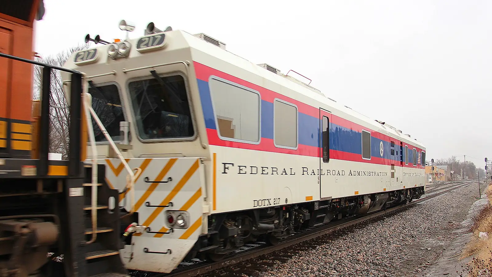
Ultrasonic rail test cars are automated ultrasonic systems: multi-channel probe carriages run along the rail, record signals by position, and send suspect locations for interpretation and field verification. Under 49 CFR 213.240, a track owner may meet the 213.237 internal inspection requirement with continuous testing, in which the vehicle runs non-stop and data is analyzed afterward.
FRA's 2014 rail integrity rule described four rail test processes: a portable device pushed "at a walking pace", start/stop testing at a slow speed "normally not exceeding 20 mph", a chase-car process, and continuous testing (79 FR 4234, Jan. 24, 2014). Section 213.240 was added by the October 7, 2020 rule (85 FR 63362), after continuous testing had been run for years under FRA waivers. The difference between the two vehicle modes is covered in continuous vs stop-and-verify rail testing.
The analyst-review model
Continuous testing splits the job that one operator does in stop-and-verify testing. Under 213.240(d), vehicle operators are qualified under 213.238 except for interpreting responses, and the data "must be reviewed and interpreted by a person qualified to interpret the equipment responses", whose employer keeps the qualification records. A 213.238-qualified person then goes to each suspect location in the field. The rule is explicit about status:
"A suspect location is not considered a defect under § 213.113(c) until it has been field-verified by a person qualified under § 213.238." (49 CFR 213.240(e)(4))
The clocks are short. Field verification is due within 84 hours of the vehicle's indication, or 36 hours where the suspected defect would need remedial action A, A2 or B. A suspect not verified in time gets the most restrictive remedial action for its suspected type and size under 213.240(e)(5).
Honest description matters here. The automated part is detection and recording; the decisions are human. During the waiver period, railroads sorted suspects into priority bands, and the 2020 preamble reports that the lowest-priority band was confirmed less than 2% of the time yet held about 85% of the defects that were field-verified. Those figures come from industry practice reported in the preamble, not from rule text, but they show why analyst judgment, not the vehicle, sets the outcome.
| Rail test process | Who interprets | When the defect becomes "known" | Rule |
|---|---|---|---|
| Portable (walking-pace cart or hand probe) | The operator, on the spot | On verification | 213.237, 213.238, 213.113(b) 4-hour rule |
| Stop-and-verify vehicle | The vehicle operator, who stops to hand-verify | On verification at the stop | 213.237, 213.113(b) |
| Continuous vehicle | A separately qualified data analyst, then a field verifier | Only when field-verified | 213.240(d), (e) |
Rail test cars typically show B-scan style channel maps and A-scans, not C-scans or PAUT images. PAUT on rail is still largely research and verification work: an industry research prototype ran at up to 20 mph and found transverse defects under shells, weld and web defects, but couldn't inspect the base flanges (TTCI, 2016). The next section sets hand testing and vehicle testing side by side.
Manual vs automated ultrasonic testing on rail: what does each find?
On rail, manual vs automated ultrasonic testing is not a contest: a test vehicle covers the miles and leaves a position-tagged record, a hand probe or walking cart reaches what the vehicle tests poorly, and every suspect the vehicle reports is confirmed by hand before it counts as a defect. FRA's 2014 rail integrity rule described the industry's four processes in those terms: a portable device pushed over the rail "at a walking pace while visually interpreting the test data", start/stop vehicle testing at a slow speed "normally not exceeding 20 mph", a chase-car process, and continuous testing (79 FR 4234, Jan. 24, 2014, p. 4237).
Automated ultrasonic rail testing, as this article uses the term, means a vehicle-mounted system: transducers in fluid-filled wheels or sleds at fixed angles, water sprayed on the railhead as couplant, and every channel recorded against position. Manual testing means a technician with a handheld flaw detector or a push cart, reading the screen as they go. A 1999 Colorado State University study for the Mountain-Plains Consortium put the practical difference in numbers: test cars were "capable of speeds up to 30 mph in a non-stop testing mode", but because "the vehicle stops frequently to hand verify indications", they "typically average 6 to 8 mph in practice" (MPC 99-106, Jeffrey and Peterson, Aug. 1999). FRA's 2014 cost estimate for a small railroad assumed 70 miles of Class 3 to 5 track tested in 3 days, about 23 miles a day (79 FR 4234, p. 4252). Both are dated figures from single sources, so treat them as the order of magnitude, not a quote for your line.
| Hand probe or walking cart | Test vehicle, stop-and-verify | Test vehicle, continuous (213.240) | |
|---|---|---|---|
| Probe movement | Pushed by hand; the operator watches the A-scan | Wheel or sled probes under a hi-rail or rail-bound vehicle; the operator watches a B-scan style channel display | The same vehicle, run without stopping |
| Speed | Walking pace; one cart maker rates its unit to 5 km/h (about 3 mph) | Up to 20 to 30 mph between stops; 6 to 8 mph average once verification stops are counted (MPC 99-106, 1999) | Set by the vehicle and the data system; no stops |
| Coverage per shift | A few track miles; no published standard production rate was found (search, Oct. 2026) | About 23 miles a day in FRA's 2014 small-railroad estimate | More than stop-and-verify on the same vehicle; no rule figure |
| Rail section tested | Head and web from the running surface; a hand scan can also reach the base at a weld or rail end | "the entire rail head and web, as well as the portion of the base directly beneath the web" (FRA, 2014), and "not the majority of the base" (TTCI TD-00-013, 2000) | The same as stop-and-verify |
| Record | What the operator notes; some instruments store screens | Position-tagged channel data for the run | The full data file, sent for analysis |
| Who interprets | The operator, on the spot (213.238(b)(3)) | The vehicle operator, on the spot | A separately qualified analyst (213.240(d)(2)) |
| Verification of indications | The operator hand-verifies as part of the search; 213.113(b) clocks apply | The operator stops and hand-verifies; 213.113(b) clocks apply | A 213.238-qualified person in the field, within 84 or 36 hours (213.240(e)) |
| Where it earns its place | Welds, plug rail, suspect verification, short segments, stretches where the vehicle lost its bottom echo | Routine 213.237 searches over tens of miles | High-mileage routes where the owner has adopted 213.240 procedures |
Neither column replaces the other. The vehicle is the only practical way to search a subdivision inside a 370-day or 30 MGT interval, and the hand probe is the only way to turn one of its indications into a defect. For the two manual platforms, see the ultrasonic rail detection cart and hi-rail truck vs inspection cart.
Duties that stay with a person, whatever the equipment
Part 213 never names ultrasonic testing, a test speed or a calibration method. What it regulates is the person: 213.237(i) requires that "the person assigned to operate the rail defect detection equipment must be a qualified operator as defined in § 213.238", and 49 CFR 213.238 sets a documented training program, at least 160 hours of supervised rail flaw detection experience, demonstrated proficiency "for each type of equipment", and written employer authorization for four duties. A cart and a test vehicle are different equipment types, so qualification on one doesn't carry to the other. FRA's 2014 preamble is blunt about where interpretation sits:
"Interpretation of the reflected signal is the responsibility of the test system operator." (79 FR 4234, p. 4237)
| Duty | Rule | With a hand probe or cart | With a test vehicle |
|---|---|---|---|
| Conduct a valid search with the equipment type you are qualified on | 213.238(b)(1), 213.237(i) | The operator | The vehicle operator |
| Determine that the equipment "is performing as intended" | 213.238(b)(2) | The operator | The vehicle operator |
| Interpret equipment responses and institute action | 213.238(b)(3) | The operator | The operator (stop-and-verify) or the data analyst (continuous, 213.240(d)(2)) |
| Judge that the search was continuous and "not compromised due to environmental contamination, rail conditions, or equipment malfunction" | 213.238(b)(4), 213.237(g) | The operator | The vehicle operator |
| Verify an indication | 213.113(b): within 4 hours, or immediately for a suspected A, A2 or B defect | The operator or the owner's verifier | Stop-and-verify: at the stop. Continuous: a 213.238 person within 84 or 36 hours (213.240(e)) |
| Decide whether the track stays in use | 213.113(a): a person designated under 213.7 | The owner's designated person | The owner's designated person |
| Detect defects between joint bars | 213.237(f) | A requirement on the equipment | A requirement on the equipment |
A stretch the operator judges invalid doesn't count as inspected under 213.237(g), and the owner then has until the time or tonnage limit to re-search it, slow trains to 25 mph, or replace the rail (213.237(h)). That judgment belongs to the qualified operator on both platforms.
How hand testing and test vehicles complement each other
- Verification. A vehicle produces indications; a person decides what they are. MPC 99-106 reported in 1999 that "70 to 80 percent of rail detector car indications prove false during hand test verifications", and the 2020 continuous-testing preamble reported that the lowest-priority suspects were confirmed less than 2% of the time. Both figures are dated and belong to their own systems, but they explain why the hand test, not the vehicle, sets the day's average speed. See false calls in rail UT.
- Welds. A vehicle's probes miss most of the base, which is why TTCI's thermite weld survey called its detector-car weld data "likely skewed as the ultrasonic rail flaw detection process only scans the head and web of the rail, and not the majority of the base" (TD-00-013, Kristan, July 2000). A hand scan of the weld base closes that gap; see aluminothermic weld inspection.
- Plug rail. 213.237(c)(1) requires any replacement plug rail in track that is subject to the section to have been tested for internal flaws. The NTSB's Nodaway, Iowa brief (RAB-02/01, on the 2001 derailment) found that the failed 15 ft 6 in. plug "did not receive an ultrasonic inspection before or after installation" even though the line itself was scanned about every 30 days. A stored length of rail is tested by hand or cart, not by a vehicle.
- Lost bottom echo. At New Brighton, Pennsylvania (NTSB RAR-08/02, on the 2006 derailment), the initiating defect lay inside a roughly 2 in. stretch where the test car's 0° channel had lost its bottom echo, and the railroad's instruction at the time required a rerun only when the loss ran 5 ft or more. Its post-accident instruction required unexplained loss-of-bottom areas to be ground and hand tested, and limited test speed to 5 mph on critical bridges. That is one railroad's instruction, not a rule, but it shows the division of labor.
- Shared limits. Neither platform sees through a shell. In TTCI's 1998 benchmark of six hi-rail systems on 49 known flaws, transverse defects under shells were detected about 62% of the time (7 cases) against 77% with no surface anomaly (33 cases), and the overall hit rate was 72% (TD-99-006, 1999). Hand testing brings its own variation: FRA's 2026 study found that no two operators produced statistically similar calibration results (DOT/FRA/ORD-26/07).
Worked example: a 50-mile short line. Inputs, assumed for the example: 50 track miles of Class 3 track; a stop-and-verify vehicle running 15 mph between stops, 1 suspect per mile and 6 minutes per hand verification; a walking cart pushed at 2.5 mph for 5 productive hours a shift.
- Vehicle moving time: 50 ÷ 15 = 3.33 h, or 200 min. Verification: 50 × 6 = 300 min. Total 500 min, or 8.3 h of track time, for an average of 50 ÷ 8.33 = 6.0 mph, inside the 6 to 8 mph that MPC 99-106 reported. The verification stops take more of the day than the moving.
- Cart: 50 ÷ 2.5 = 20 h of pushing, or 4 shifts, before any verification time is added.
| Item | Stop-and-verify vehicle | Walking cart |
|---|---|---|
| Moving time for 50 miles | 200 min | 1,200 min (20 h) |
| Verification time at 1 suspect per mile | 300 min | Not separately counted |
| Track time for the search | 8.3 h | 4 shifts of 5 h |
| Average speed | 6.0 mph | 2.5 mph pushing |
| What it leaves behind | A position-tagged data file and the verified defect list | The operator's notes and marked rail |
The cart's four shifts are not wasted; they are better spent where the vehicle isn't the right tool: the welds, the plug rail in the stockpile, the suspects the vehicle flagged, and the short segments where track time comes in minutes rather than hours. Any in-track test, cart or vehicle, still needs track time and on-track protection under 49 CFR Part 214.
Key takeaway: the vehicle covers the subdivision and the hand probe decides what it found; plan the two together, not as alternatives.
Does AUT remove the need for qualified operators?
No. Automated ultrasonic systems move the operator's skill from the hand to the setup and the screen, and every code that recognizes AUT still requires qualified personnel and a demonstrated procedure. The machine repeats whatever setup it is given, including a wrong one.
The work a qualified person still owns includes:
- Scan plan and ray-tracing: choosing offsets, angles and focal laws so every part of the weld volume is covered, as in the worked example above.
- Calibration and validation: proving the setup on a reference block with the right curvature and reflectors, then rechecking it at the intervals the procedure sets. ASME's Code Case 2235 and ASTM E1961 both build in demonstration.
- Data quality checks: looking for coupling loss, encoder slip and missing lines before accepting the file.
- Interpretation and sizing: separating flaw signals from weld geometry, and sizing with care. ASTM E2700-26 warns that "Extreme caution should be used when attempting to size indications using phased array", because beam spread can oversize them.
- Disposition: applying the acceptance criteria that the construction code, ECA or owner sets.
In the US, NDT personnel are certified by their employer under ASNT's recommended practice SNT-TC-1A or the ANSI/ASNT CP-189 standard, not by ASNT or by FRA. Some codes add method-specific experience on top; the D1.1 PAUT annex is reported to require PAUT experience hours and a practical examination on flawed samples (confirm the numbers in your edition). On rail, 213.238 and 213.240(d) set who may operate and who may interpret.
Human variation doesn't disappear with automation either. An FRA study of handheld rail UT (DOT/FRA/ORD-26/07, 2026) found that, with a small exception, no two operators produced statistically similar calibration results, and noted that "calibration errors can cause excessive false positives and false negatives". An encoded system freezes whatever calibration it was given into every A-scan it stores.
What does probability of detection mean for AUT?
Probability of detection (POD) is a curve, not a single percentage: it rises with flaw size and depends on the technique, the setup, the flaw type and the detection threshold. A claim such as "AUT detects 95% of weld defects" means nothing until it says which flaws, what size, at what threshold, and with what confidence.
POD studies fit a curve to many trials on known flaws. The common summary point, a90/95, is the flaw size detected with 90% probability at 95% confidence, a convention from the US Air Force handbook MIL-HDBK-1823A (2009). ASTM has standard practices for the analysis: E2862-23 for hit/miss data and E3023-21 for signal-response (â versus a) data, both active.
The FRA's 2026 study of handheld rail UT shows how much one setting moves the answer. Using 512 simulated responses for flaws of 1% to 76% of head area, it reported POD at 25% head area for different detection thresholds:
| Detection threshold | Mean POD at 25% head area | Lower 90% bound | Lower 95% bound |
|---|---|---|---|
| 0.10 | 99.9% | 98.2% | 97.3% |
| 0.25 | 95.8% | 93.6% | 93.1% |
| 0.40 | 86.7% | 84.1% | 83.5% |
Source: DOT/FRA/ORD-26/07, Table 24 (simulated handheld UT on rail; not a weld AUT study). The same report warns that "too low a detection threshold can result in an unacceptable number of false positives". Raising POD by lowering the threshold costs false calls, so POD can only be compared between systems at matched false-call rates.
Field condition shifts the curve as well. A TTCI study of transverse defects found detection of 62% under shelled rail (7 cases) against 77% where there was no surface anomaly (33 cases), and an industry research digest put conventional rail UT at "about 90 percent" of flaws in periodic inspection (TTCI TD-16-030, 2016). Each figure belongs to its own system and conditions and shouldn't be carried over to weld AUT.
The original version of this article said UT detects "defects as small as one millimeter". That figure has no meaning without frequency, material, flaw orientation and the threshold used. A 1 mm planar flaw lying parallel to the beam may be missed, while a 1 mm side-drilled hole at the right depth is easy to see.
Key takeaway: ask for a POD curve for your flaw type and condition, with the threshold and confidence stated, or a demonstration on your own blocks.
What are the limits of automated ultrasonic systems?
Automated ultrasonic systems share all the physical limits of manual UT and add some of their own. Knowing them is what lets an engineer read an AUT report correctly.
- Geometry and access. Scanners need a clean, continuous surface and room for the band or carriage. Nozzles, branch connections, tight fit-ups and short welds often go back to manual UT.
- Fixed bevel assumptions. Zonal AUT is set up for one weld bevel. A change in bevel, wall thickness or diameter needs a new calibration block and setup, which is why ASTM E1961 ties its zones to the weld profile.
- Coverage gaps. An S-scan sweep is not automatic full coverage. The worked example shows that a probe outside a 21.3 to 34.9 mm offset window misses the root or the cap.
- Dead zones. TOFD can't see flaws in the lateral-wave zone near the surface or close to the back wall, and pulse-echo contact probes have their own near-surface limits.
- Coarse-grained and austenitic material. Attenuation and beam skewing in austenitic welds and castings limit any UT, automated or not. ISO 13588, for example, is written for low-alloy and fine-grained steel, so coarse-grained welds need a separately demonstrated technique.
- Sizing uncertainty. Amplitude-based length and height sizing can over- or under-size; PAUT oversizing from beam divergence is a known issue.
- Data volume. Tens of thousands of A-scans per weld need disciplined review. A missed indication in a stored file is still a missed indication.
- On rail: shelling and head checks mask what lies beneath, fixed-angle probes on worn rail may look at "the wrong volume of material" (TTCI), and test cars cover the head, web and only the part of the base beneath the web. Hand testing has limits of its own: coverage rests on the operator's statement, calibration varies between operators, and a walking pace cannot search a subdivision inside a 370-day or 30 MGT interval.
How should you specify an AUT job?
Name the technique document, the acceptance criteria, the demonstration, the data deliverable and who reviews it. Most AUT disputes come from a contract that says "AUT per code" without saying which code governs acceptance.
- Governing code and edition: API 1104 (and which edition, if 49 CFR 192 applies), the Section VIII or B31.3 construction code with Code Case 2235, or AWS D1.1 with its PAUT annex.
- Technique practice: ASTM E1961 for zonal AUT, ASME V Article 4 with its appendices, ASTM E2700 for PAUT, ASTM E2373 for TOFD.
- Acceptance criteria: the code's own workmanship limits, or an ECA (API 1104 Annex A). Technique documents don't supply them.
- Procedure demonstration: the reference block (material, curvature, reflector types) and who witnesses it.
- Scan plan: offsets, angles and focal laws, with the ray-trace showing each part of the weld covered.
- Data deliverable: native files plus a viewer, encoder records, calibration records and the indication table.
- Review: whether an owner's Level III reviews data independently, and on what sample.
- Personnel: the certification route (SNT-TC-1A or CP-189 written practice) and any method-specific experience the code requires.
How EMA Industries applies this
EMA Industries performs ultrasonic rail flaw testing for transit agencies, short lines and industrial track owners, and AWS D1.1 structural weld UT, from Southern California with nationwide mobilization. Our NDT Level III services can help owners write or review a UT procedure, check a scan plan's coverage, and read an inspection report against the code and edition named in the contract. To discuss a rail testing program or a weld inspection scope, see our ultrasonic examination services or contact EMA Industries.
Related reading
- What's the difference between UT and PAUT?
- Continuous vs stop-and-verify rail testing
- Types of ultrasonic testing in NDT
- ASME weld ultrasonic inspection
- PAUT vs TOFD for rail weld inspection
- Hi-rail truck vs inspection cart
- False calls in rail UT
FAQ
What is the difference between AUT and PAUT?
AUT describes how the scan is done: probe movement is mechanized or encoded and the full data set is recorded. PAUT describes the probe: a multi-element array whose beam is steered electronically. PAUT can be manual or encoded, and AUT can use phased array, conventional focused probes (as in zonal discrimination) or TOFD.
Does API 1104 require automated ultrasonic testing?
It doesn't. API 1104 permits radiography, manual UT and mechanized UT; the company or a regulator decides which method is used. Washington's WAC 480-75-460 is one example of a regulator requiring radiography or automatic UT for hazardous liquid girth welds. Projects using the Annex A ECA acceptance route need height sizing, which in practice means AUT.
Is a rail test car an automated ultrasonic system?
A rail test car is an automated ultrasonic system: fixed probe carriages run along the rail and record signals by position. In stop-and-verify mode the operator stops to hand-verify each suspect, while in continuous mode under 49 CFR 213.240 a separately qualified analyst reviews the data and a 213.238-qualified person field-verifies each suspect within 84 or 36 hours.
Is manual or automated ultrasonic testing more accurate on rail?
They answer different questions, so neither is "more accurate" as a method. Benchmark data exists for vehicles: six hi-rail systems found 72% of 49 known flaws on TTCI's test track in 1998 (TD-99-006), and a 2016 TTCI digest put conventional car testing at about 90% of flaws in periodic inspection (TD-16-030). No public study was found that compares the detection probability of walking carts or hand probes with vehicles (search, October 2026). In practice the vehicle finds the indications and the hand probe confirms them, so the program's accuracy depends on both.
How accurate is automated ultrasonic testing?
Accuracy depends on the flaw type, size, orientation, material, setup and detection threshold, so it is expressed as a POD curve, not a single percentage. Ask for the a90/95 flaw size for your flaw type, the false-call rate at the same threshold, and a demonstration on a block that matches your weld.
Can automated ultrasonic systems replace radiography?
They can where the governing code allows it. ASME Code Case 2235 permits UT in lieu of RT for boiler and pressure vessel welds under set conditions, and API 1104 accepts AUT for girth welds. The owner must also accept the change, and the procedure must be demonstrated before production work.
Sources
- 49 CFR 213.240, Continuous rail testing (eCFR); text read on Cornell LII, October 2026
- 49 CFR 213.237, Inspection of rail (eCFR); text read on Cornell LII, November 2026
- 49 CFR 213.238, Qualified operator (eCFR); text read on Cornell LII, November 2026
- 49 CFR 213.113, Defective rails (eCFR); text read on Cornell LII, November 2026
- Jeffrey and Peterson, Assessment of Rail Flaw Inspection Data, MPC 99-106, Colorado State University, Aug. 1999 (UGPTI PDF)
- TTCI Technology Digest TD-00-013, Thermite Weld Failure Survey, Kristan, July 2000 (MxV Rail)
- TTCI Technology Digest TD-99-006, Benchmarking Results of North American Rail-Flaw Detection Technologies, Garcia and Reiff, Feb. 1999 (MxV Rail)
- NTSB Railroad Accident Brief RAB-02/01, Nodaway, Iowa, March 17, 2001 (PDF)
- NTSB Railroad Accident Report RAR-08/02, New Brighton, Pennsylvania, October 20, 2006 (PDF)
- 49 CFR 192.7, Incorporation by reference, API 1104 21st edition (eCFR)
- FRA final rule, Rail Integrity and Track Safety Standards, 85 FR 63362, Oct. 7, 2020 (govinfo)
- FRA final rule, Improving Rail Integrity, 79 FR 4234, Jan. 24, 2014 (govinfo PDF)
- Washington WAC 480-75-460 (Cornell LII)
- ASTM E1961-16(2021), Mechanized UT of Girth Welds Using Zonal Discrimination (ASTM store)
- ASTM E2700-26, Contact UT of Welds Using Phased Arrays (ASTM store)
- ASTM E2373/E2373M-19(2024), TOFD (ASTM store)
- ASTM E2862-23, POD Analysis for Hit/Miss Data (ASTM store)
- ASTM E3023-21, POD Analysis for â Versus a Data (ASTM store)
- ASME BPVC Section V, Nondestructive Examination (ASME)
- FRA DOT/FRA/ORD-26/07, MAPOD for handheld rail UT, 2026 (ROSA P)
- TTCI Technology Digest TD-16-030, High-Speed Rail Flaw Detection Using Phased Array Ultrasonics, 2016 (MxV Rail)
- Ghaemi, API 1104 and AUT history, ECNDT 2014 (NDT.net)
- Sonatest, PAUT of welds under AWS D1.1:2020 (vendor blog, 2023)
- ASNT standards: SNT-TC-1A and CP-189