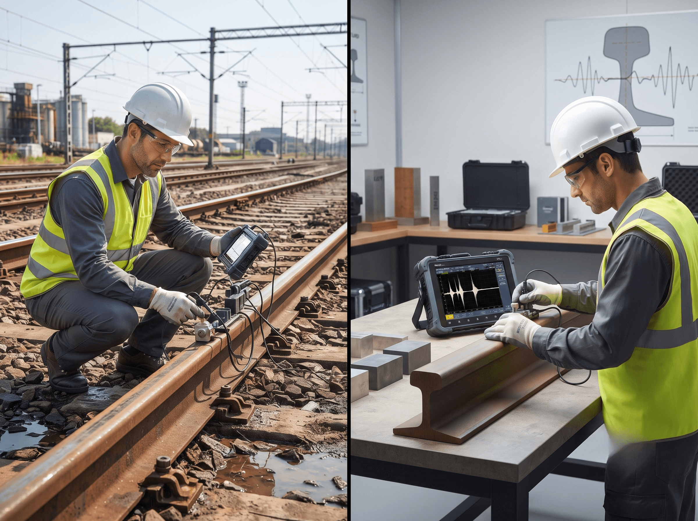
False calls in rail UT are ultrasonic indications that are reported as possible rail defects but turn out, on verification, to be something else: a bolt hole, a weld, a surface condition or a loss of coupling. Under 49 CFR 213.113(b), each indication must be verified within 4 hours, or within 84 hours under continuous testing (213.240).
A false call costs time and track access. A missed defect can cost a derailment. Every rail flaw testing program sits between those two errors, and the setting that reduces one usually increases the other. This guide explains the difference, the rail-specific causes of false calls, what FRA rules say about verifying suspects, and what FRA and TTCI research shows about the trade-off.
What is the difference between a false call and a missed defect?
A false call is a suspect that isn't a defect; a missed defect is a real defect that produced no suspect. In inspection-reliability language, the first is a false positive and the second is a false negative.
| Inspection result | What is in the rail | What the test reports | Consequence |
|---|---|---|---|
| True positive (hit) | A reportable defect | A suspect that verifies as that defect | Remedial action under 213.113 |
| False positive (false call) | No reportable defect | A suspect that verifies as a bolt hole, weld, surface condition or nothing | Wasted verification time, track access and sometimes a speed restriction |
| True negative | No reportable defect | No suspect | None |
| False negative (missed defect) | A reportable defect | No suspect | The defect stays in track until the next test, or until it breaks |
The two errors are not equal. A false call is an operating cost. A missed transverse defect is a safety risk, because transverse fissures and detail fractures are among the defect types that count as service failures under 49 CFR 213.237 when they break in service.
Two related outcomes are often lumped in with false calls but are different:
- A misclassified defect. The suspect is real but is called the wrong type or size. A transverse defect sized at 15% of the head area that is actually 30% falls under a different remedial action in the 213.113 table.
- An invalid search. The equipment could not test a stretch of rail at all, for example because coupling was lost. That isn't a false call. It is untested rail, and 213.241 requires the owner to record the location of track not tested under 213.237(g).
Key takeaway: count false calls, missed defects and untested stretches separately, because each has a different fix.
What do FRA rules require when rail UT flags a suspect?
Federal rules treat an ultrasonic indication as something to verify, not yet as a defect. The verification window depends on how the test is run.
| Test mode | Rule | Verification window | If not verified in time |
|---|---|---|---|
| Stop-and-verify (the conventional method) | 49 CFR 213.113(b) | Within 4 hours; immediately if the indicated defect would need remedial action A, A2 or B | The rule gives no grace period; the owner must verify |
| Continuous rail testing, when used for a 213.237 or 213.339 inspection | 49 CFR 213.240(e) | Within 84 hours; within 36 hours if the suspected defect would need action A, A2 or B | Apply the most restrictive remedial action for the suspected type and size, over enough track to cover the location |
Under continuous testing, the rule is explicit that a suspect is not yet a defect:
"A suspect location is not considered a defect under § 213.113(c) until it has been field-verified by a person qualified under § 213.238." (49 CFR 213.240(e)(4))
Other parts of 213.240 bear directly on false calls:
- The owner's procedures must ensure suspects are "accurately identified for field verification", categorized and prioritized by potential severity, and "accurately field-verified" (213.240(b)).
- The test data must be reviewed by a person qualified to interpret the equipment responses (213.240(d)(2)).
- Each suspect must be recorded "with repeatable accuracy" so the verifier can find it again (213.240(f)).
- The annual report to FRA lists defects and service failures per segment (213.240(g)). It does not ask for the number of suspects that turned out not to be defects, so a false-call rate is something the owner and contractor must track themselves.
A valid search under 213.237 is also defined in terms of interpretation: "a continuous inspection for internal rail defects where the equipment performs as intended and equipment responses are interpreted by a qualified operator." Interpretation is part of the legal definition of a test, not an optional step.
Worked example: when must a continuous-test suspect be verified?
A continuous test car flags a suspect at 14:00 on Tuesday. The suspect pattern suggests a transverse defect.
| Scenario | Window | Deadline |
|---|---|---|
| Suspected defect that, if verified, would need action C or D | 84 h | Tuesday 14:00 + 72 h = Friday 14:00, + 12 h = Saturday 02:00 |
| Suspected defect that, if verified, would need action A, A2 or B | 36 h | Tuesday 14:00 + 24 h = Wednesday 14:00, + 12 h = Thursday 02:00 |
| Not verified by the deadline | — | Apply the most restrictive 213.113(c) action for the suspected type and size until verified |
Every false call in that list still consumes a verification visit inside the window. On a run with many suspects, the false-call rate decides whether the verification crew can meet the 36-hour deadlines.
Why does reducing false calls in rail UT risk missing defects?
Because both errors are controlled by the same detection threshold. Lowering the threshold catches smaller and weaker reflectors, but it also passes more noise and benign geometry as suspects. Raising it does the opposite.
FRA's 2026 report on model-assisted probability of detection, DOT/FRA/ORD-26/07 (Bruzek, Einbinder and Tunna, ENSCO), quantified the missed-defect side for handheld 70° rail UT. It simulated 512 responses for flaws from 1% to 76% of the rail head area and states the trade-off directly: "too low a detection threshold can result in an unacceptable number of false positives," while too high a threshold gives unacceptable false negatives.
Its Table 24 shows how probability of detection (POD) for a flaw of 25% head area falls as the threshold rises (full dataset of rail profiles, simulated):
| Detection threshold (normalized amplitude) | Mean POD | Lower 90% confidence POD |
|---|---|---|
| 0.10 | 99.9% | 98.2% |
| 0.15 | 98.7% | 96.8% |
| 0.20 | 97.2% | 95.1% |
| 0.25 | 95.8% | 93.6% |
| 0.30 | 93.8% | 91.4% |
| 0.35 | 90.0% | 87.4% |
| 0.40 | 86.7% | 84.1% |
Source: DOT/FRA/ORD-26/07, Table 24. The study did not measure false calls, so the table shows only one side of the trade-off.
Worked example: what a threshold change means for 200 flaws
Take 200 transverse flaws, each 25% of the head area, the size at which a transverse fissure moves from remedial action C to action D in the 213.113 table. Using the mean POD values above:
| Threshold | Mean POD | Expected detections | Expected misses |
|---|---|---|---|
| 0.15 | 98.7% | 200 × 0.987 = 197.4 | about 3 |
| 0.25 | 95.8% | 200 × 0.958 = 191.6 | about 8 |
| 0.40 | 86.7% | 200 × 0.867 = 173.4 | about 27 |
Raising the threshold from 0.25 to 0.40 would cut some false calls, but in this simulation it would roughly triple the expected misses at this flaw size. The report's own headline uses the lower confidence bound: at a 0.25 threshold there is a 90% probability that a 25%-head-area flaw is detected more than 187 times in 200 (93.6% × 200 = 187.2).
These numbers come from a simulation of handheld UT under the study's stated assumptions. They are not a detection rate for any test car or contractor, and a buyer shouldn't quote them as one.
Key takeaway: a program that brags about very few false calls may simply be running a high threshold. Ask what POD it gives up.
What causes false calls in rail UT?
Most false calls come from real reflectors that aren't defects, or from changes in coupling that look like defect signatures. TTCI put the rail version plainly in Technology Digest TD-16-030 (2016): "Not all indications are from defects." It names bolt holes and some welds as features with distinct ultrasonic signatures that must be told apart from defects, and from bolt holes and welds that do contain defects.
| Source | Where it occurs | How it can look on the test | How it's usually separated from a defect |
|---|---|---|---|
| Bolt holes | Rail ends at joints, in the web | Strong web reflection on angled and 0° channels; loss of base echo over the hole | Repeats at known hole spacing on both sides of every joint; a crack shows as an extra indication off the hole. See bolt hole cracks |
| Rail ends and joint gaps | Bolted and insulated joints | Full-section reflection where the rail ends | Coincides with the joint location; the test must still cover the rail between the bars under 213.237(f) |
| Welds | Thermite and flash-butt welds | Reflections from the weld collar, upset or un-ground flashing | TTCI TD-16-050 notes un-ground flashing and material changes at welds "can cause reflections that must be distinguished from true defects" |
| Worn rail profile | Curves, gauge corner | Beam refracts into a different volume than intended; spurious or missing head echoes | TD-16-030 notes that on worn rail "the wrong volume of material is inspected"; hand-scan with a probe suited to the profile |
| Shelling, spalling, head checks | High rail on curves, RCF zones | Shallow horizontal reflections and scattering; can resemble a horizontal split head, or mask a defect beneath | Visual check of the running surface; hand-scan from other positions. See rail shelling and spalling |
| Corrugation | Short-pitch on transit and curves | Dropouts and loss of back-wall echo repeating at the corrugation pitch | Indications at the same spacing as the corrugation are coupling, not flaws. See corrugation on rail |
| Grinding marks and fresh grinding | After corrective or preventive grinding | Faceted surface and residue can change probe contact and noise | Re-test after the surface is cleaned; see rail grinding and its effect on UT |
| Loss of coupling | Contamination, dry rail, worn wheels or sleds, heavy gauge face wear | Loss of back-wall echo across several channels at once | A loss on all channels together, or on both rails, points to coupling rather than an internal reflector |
| Electronic and mechanical noise | Any | Random indications that don't repeat on a second pass | Re-run or hand-scan; a real reflector repeats |
| Calibration and operator variation | Any | Over-sensitive gain produces more suspects; under-sensitive gain produces misses | Calibration records and a reference standard check; see UT calibration for rail inspection |
The probe-to-indication descriptions in this table reflect typical North American practice and vary by equipment. A Level III should confirm them for the specific test system before they are used in a procedure.
Why geometric reflectors cause most interpretation calls
Rail UT works by listening for echoes, and a rail is full of surfaces that echo: the base, the head-web fillet, bolt holes, rail ends and welds. TD-16-030 describes the conventional system as roller search units with fixed-angle probes, where "a trained operator learns to discern the difference between defects and normal features such as bolt holes and welds." The call becomes false when a normal feature is read as a defect, or when a feature sits where the operator didn't expect it, such as an unrecorded field weld or a plug rail with different bolt-hole spacing.
Why surface condition and coupling cause both errors
Surface condition is the cause that works in both directions. Shelling, head checks, corrugation and contamination can produce indications that aren't defects, and they can also scatter the beam so that a real defect underneath gives a weak or no response. TTCI's 1999 benchmarking of six hi-rail systems at the Rail Defect Test Facility (TD-99-006) found a hit rate of about 62% for transverse defects under shells against 77% for those not under shells. That is a missed-defect problem, not a false call, and the figures are old, but the mechanism hasn't changed.
FRA research report RR 22-36 (2022), on expanding the Rail Flaw Library of Associated Defects (RF-LOAD) at the Transportation Technology Center, describes acoustic coupling as a limitation of conventional rail UT. The library holds artificial reflectors (mainly flat-bottom holes representing about 1% to 30% of the head area) and, since 2017, naturally occurring flaws in rail pulled from service, so that inspection methods can be checked against real wear profiles and surface conditions.
Key takeaway: when indications cluster in a stretch of poor surface, treat the stretch as a testability problem first, not as a cluster of defects.
What is loss-of-bottom, and is it a false call?
Loss-of-bottom is a drop in the 0° back-wall (base) echo; it can mean a horizontal reflector in the head, or simply that the surface is scattering the sound. TTCI's Technology Digest TD-18-027 (Cummings, November 2018) defines it this way:
"If the reflected signal strength decreases, it can be a sign that anomalies at or near the rail surface, such as RCF or spalling, may be scattering a portion of the ultrasonic signal. This is commonly referred to as 'loss-of-bottom.'"
Loss-of-bottom from surface damage is not a defect, but treating it as a clean test would be a mistake. TTCI drilled 1/8 in. holes in five rails removed from service for low-confidence UT results and compared their response with the same hole in a control rail with good surface condition. Using a 70° hand probe, the damaged rails returned on average 67% of the control response, and never less than 15%. Of 880 cracks and spalls measured, 90% were no deeper than 0.040 in.
Worked example: converting TD-18-027 responses to decibels
Signal ratio in decibels is 20 × log10(A1 / A2).
| Location in TD-18-027 Table 1 | Average relative response | Loss in dB |
|---|---|---|
| Gage side | 68% | 20 × log10(0.68) = −3.3 dB |
| Center of head | 52% | 20 × log10(0.52) = −5.7 dB |
| Field side | 80% | 20 × log10(0.80) = −1.9 dB |
| All 22 holes | 67% | 20 × log10(0.67) = −3.5 dB |
| Worst case | 15% | 20 × log10(0.15) = −16.5 dB |
A 3.5 dB average loss means small internal reflectors were still detectable through that surface, which is TTCI's conclusion. The 16.5 dB worst case is the risk: a reflector that would sit well above the threshold on clean rail could fall below it. TTCI estimated that three to five production grinder passes would likely have restored UT confidence in these rails.
Key takeaway: loss-of-bottom from surface damage is a testability finding. Record it, plan grinding or a hand test, and don't count the stretch as cleanly searched.
How are suspects verified in the field?
A qualified operator returns to the suspect and hand-tests it with probes chosen for the suspected defect, then decides whether it is a defect, a known feature or nothing. Under 213.240(d)(3), every continuous-test suspect must be field-verified by a person qualified under 49 CFR 213.238. Under stop-and-verify testing, the operator usually leaves the test vehicle and hand-scans the location; TD-18-027 describes exactly that step.
A typical verification sequence:
- Locate the suspect from the recorded milepost, GPS or offset, and confirm it against nearby joints, welds and other landmarks.
- Look first. Check the running surface for shelling, head checks, corrugation, grinding marks, burns and contamination, and the web for bolt holes, welds and joint bars.
- Check the instrument against the calibration standard so the hand test doesn't inherit a calibration error.
- Clean and couple the scan area so that a coupling loss isn't mistaken for a flaw.
- Hand-scan from several positions and angles. A real reflector stays put and behaves consistently; a geometric reflector matches known geometry; noise disappears.
- Classify and size the indication by the 213.113(d) defect definitions and the percentage of head area or length used in the remedial action table.
- Mark and record. A verified defect is marked under 213.237(e) and recorded under 213.241. A false call should be recorded too, with its cause.
- Feed it back. Recurring false calls at the same features (for example, every bolt hole on one rail section) point to a threshold, gate or probe setup the test operator can adjust.
FRA's 2026 MAPOD study found that handheld UT calibration itself varies between operators. With a small exception, no two operators in its laboratory tests produced statistically similar calibration results, and one operator using the same equipment on six occasions produced inconsistent results. The report also notes that the North American railroad industry has no standardized calibration procedure for this equipment. That variation affects verification, not just the original test.
How can a testing program reduce false calls without losing sensitivity?
Reduce the causes of benign indications, and leave the detection threshold where the POD needs it. The table below sorts common measures by what they change.
| Measure | Reduces false calls by | Effect on missed defects |
|---|---|---|
| Keep an up-to-date asset list (joints, welds, plugs, insulated joints) | Letting the operator expect known reflectors | Neutral or better |
| Grind before testing where RCF and loss-of-bottom are known | Removing scattering surfaces | Better: fewer masked defects (TD-18-027) |
| Control coupling (couplant, wheel and sled condition, test speed on poor rail) | Avoiding dropouts that mimic defects | Better. See ultrasonic couplant for rail inspection |
| Require agreement between channels before calling a suspect | Filtering single-channel noise | Small risk for defects only one probe can see |
| Raise the detection threshold | Passing fewer weak indications | Worse: POD falls (ORD-26/07 Table 24) |
| Review recurring false calls by location and rail type | Fixing setups that misfire at the same features | Neutral or better |
| Record untested stretches separately | Keeping invalid searches out of the false-call count | Better: untested rail gets retested |
TTCI's phased array work in TD-16-030 makes the multi-channel point: when several probes see an indication at the same location, confidence in the detection rises and the likelihood of a false alarm falls. TD-16-050 adds that a phased array prototype "is still a head contacting inspection technique" and can't inspect the rail base flanges, so no probe arrangement removes every limit.
FRA's 2021 MAPOD feasibility report (RR 21-18) found ultrasonic rail flaw detection the most feasible of six track inspection types for MAPOD, and its companion roadmap (RR 21-19) set out how to apply it. The 2026 report is the result. None of these reports sets a required false-call rate or POD; they are research, not rules.
What rail UT can't tell you
These limits apply to every false-call reduction effort, however good the equipment:
- A low false-call rate is not evidence of a good test. It can mean a high threshold or poor coverage. Ask for POD evidence and untested-stretch records alongside it.
- Surface damage can hide defects as well as create false calls. Shelling and RCF masked transverse defects in TTCI's 1999 benchmarking, and loss-of-bottom cut 70° response by up to 16.5 dB in TD-18-027.
- Head-contacting UT has blind areas. TD-16-050 notes the base flanges can't be inspected from the head. Thermite weld bases and web corrosion under crossings usually need hand testing or other methods.
- Verification depends on the verifier. ORD-26/07 found large differences in calibration between operators. A verification is only as good as the calibration and procedure behind it.
- Research POD figures are conditional. The ORD-26/07 values come from simulated handheld UT on specific rail profiles and flaw shapes, not from test cars in service.
- Federal rules don't measure false calls. 213.240(g) reporting covers defects and service failures, not suspects that proved benign.
How EMA Industries applies this
EMA Industries performs ultrasonic rail flaw testing for transit agencies, short lines and industrial track owners, based in Southern California and mobilizing nationwide. On a false-call problem, the useful deliverable is a report that separates verified defects, suspects proven benign (with their cause), and stretches that couldn't be validly searched, so the owner can see whether the issue is setup, surface condition or real rail. To scope a testing program or a re-test of a problem section, see our ultrasonic rail testing services or contact EMA Industries.
Related reading: 49 CFR 213.237 rail flaw detection requirements · FRA defect codes and 213.113 remedial actions · How ultrasonic rail flaw detection works · Rail joint inspection with UT
Frequently asked questions
What is an acceptable false-call rate in rail ultrasonic testing?
No federal rule sets one. 49 CFR 213.240 requires suspects to be accurately identified and verified, and its annual report covers defects and service failures, not benign suspects. A false-call rate is a contract and performance measure the owner and contractor agree on, and it should always be read together with POD and untested-stretch data.
How quickly must a rail flaw indication be verified?
Under 213.113(b), within 4 hours, or immediately if the indicated defect would need remedial action A, A2 or B. Under continuous testing (213.240), within 84 hours, or 36 hours for suspected A, A2 or B defects. An unverified continuous-test suspect takes the most restrictive remedial action for its suspected type and size.
Why do bolt holes and welds trigger false calls?
They are real reflectors. A bolt hole returns a strong echo and blocks the base echo, and a weld collar or un-ground flashing can reflect sound like a defect. TTCI notes these features have distinct signatures that operators must tell apart from defects, and from bolt holes and welds that do contain cracks.
Does a loss of back-wall echo mean the rail has a defect?
Not necessarily. Loss-of-bottom can come from a horizontal split head or another internal reflector, but it can also come from surface damage, corrugation or poor coupling scattering the sound. TTCI's TD-18-027 found an average 67% relative response through damaged surfaces. Treat it as a suspect to verify and a testability problem to fix.
Can rail grinding reduce false calls?
Often, yes. Grinding removes the shallow cracks and spalls that scatter sound and cause loss-of-bottom; TTCI found 90% of measured cracks and spalls were no deeper than 0.040 in. Grinding doesn't count as a 213.237 test, so the rail still needs a valid search afterward.
Sources
- 49 CFR 213.113, Defective rails, eCFR (text read on Cornell LII, October 2026)
- 49 CFR 213.240, Continuous rail testing, eCFR (text read on Cornell LII, October 2026)
- 49 CFR 213.237, Inspection of rail, eCFR
- 49 CFR 213.238, Qualified operator, eCFR
- 49 CFR 213.241, Inspection records, eCFR
- Bruzek, R., Einbinder, D. and Tunna, J., Application of MAPOD to Handheld Ultrasonic Rail Flaw Inspection, DOT/FRA/ORD-26/07, FRA, July 2026, ROSA P
- FRA, Feasibility of Applying Model-Assisted Probability of Detection to Track Inspection, Research Results RR 21-18, September 2021, ROSA P
- FRA, Model-Assisted Probability of Detection for Ultrasonic Rail Flaw Inspection, Research Results RR 21-19, September 2021, ROSA P
- FRA, Expansion of the Rail Flaw Library at the Transportation Technology Center, Research Results RR 22-36, November 2022, FRA eLibrary
- Cummings, S., Testability and Corrective Grinding Depth of Rails with Poor Surface Condition, AAR/TTCI Technology Digest TD-18-027, November 2018
- Witte, M. and Poudel, A., High-Speed Rail Flaw Detection Using Phased Array Ultrasonics, TTCI Technology Digest TD-16-030, July 2016
- Witte, M. and Poudel, A., Characterizing Rail Flaws Using Phased Array Ultrasound, TTCI Technology Digest TD-16-050, November 2016
- Garcia, G. A. and Reiff, R. P., Benchmarking Results of North American Rail-Flaw Detection Technologies, AAR/TTCI Technology Digest 99-006, February 1999