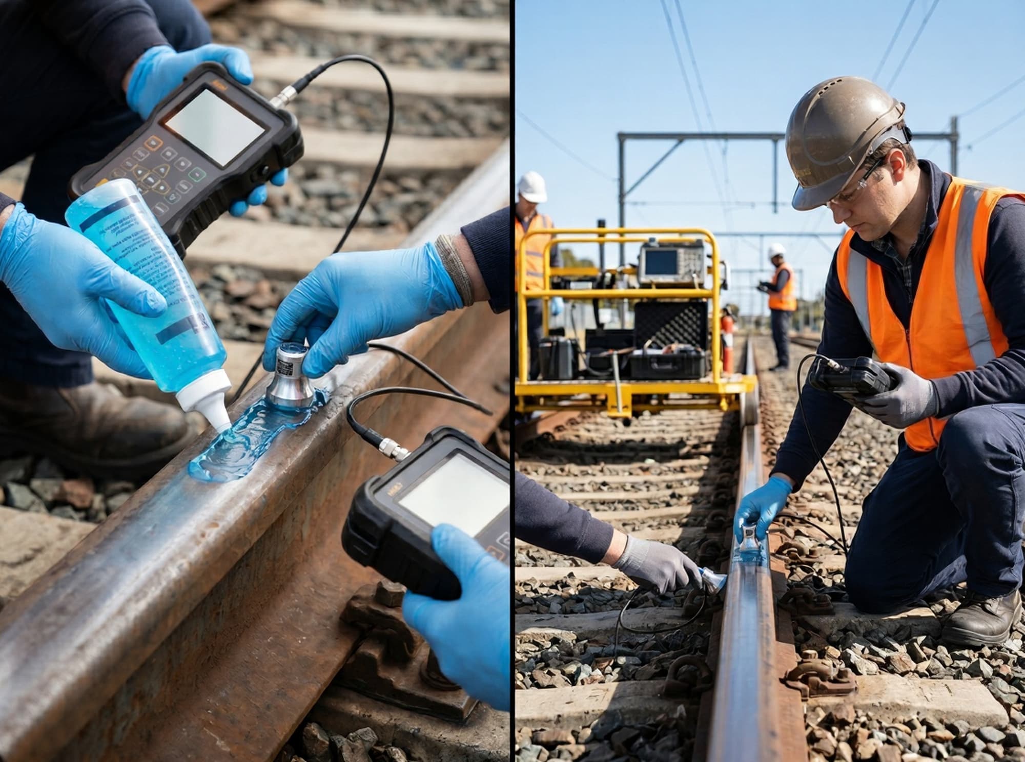
Ultrasonic couplant for rail inspection is the water, glycol mix or gel that carries sound from the probe into the rail, because a steel/air boundary reflects about 99.996% of ultrasonic energy. When coupling fails, 49 CFR 213.237(g) says that length of track may not be counted as internally inspected.
Couplant looks like a consumable, but it decides two things a track owner cares about. It sets how much sound reaches a defect, and it decides whether a stretch of rail was actually searched. This guide covers both, from the hand probe to the test car.
In this article
- What couplant does in rail ultrasonic testing
- Couplant types for hand probes, sliders and wheel probes
- Acoustic impedance, with a worked example
- Temperature and freezing
- The fluid inside a wheel probe vs the spray on the rail
- Environmental and track-side considerations from safety data sheets
- Loss-of-coupling monitoring
- What a no-test means under 213.237(g) and (h)
- What ASME Section V and ASTM standards say
- A field checklist, the limits, and an FAQ
What does couplant do in rail ultrasonic testing?
Couplant replaces the air between the probe and the rail with a liquid layer that sound can cross. Without it, almost nothing enters the steel at the MHz frequencies used for rail flaw detection.
Evident's couplant note puts it plainly: couplant is needed "because sound energy at the ultrasonic frequencies typically used for nondestructive testing is not effectively transmitted through air." It adds that "even an extremely thin air gap between the transducer and the test piece will prevent efficient sound energy transmission."
ASTM's weld examination practice describes the same job in its scope. ASTM E164-24 covers manual techniques "employing contact of the search unit through a couplant film or water column." A rail hand test uses the film; a rail test car uses a water column of sorts, inside a fluid-filled wheel.
In rail work, couplant also has a monitoring role. The rail base gives a strong, predictable echo to the 0° channel, so a steady base echo is the operator's running proof that sound is getting in. When that echo drops, the cause may be a defect, a surface condition or simply lost coupling, and the test can't tell which until someone looks.
Key takeaway: couplant is what makes a rail test possible at all, and the base echo is how the operator knows it is working.
Which ultrasonic couplant for rail inspection suits each probe type?
Hand probes usually take a gel or a water-based liquid, sliders take a water spray, and wheel probes take a sealed internal fluid plus a water spray on the rail. Each delivery method has its own failure modes, so the choice follows the equipment more than the product.
| Probe or carrier | How sound reaches the rail | Typical couplant | Main coupling risk |
|---|---|---|---|
| Hand contact probe (0° or angle beam), used to verify suspects and test welds | Probe face or plastic wedge pressed on the rail through a thin film | Gel on vertical or rough faces (web, base, weld collars); water or water-glycol on the head | Film too thick or uneven, runoff on vertical faces, air trapped on pitted steel |
| Slider or sled probe on a test car or cart | Probe shoe slides on the railhead through a sprayed water film | Water, with an antifreeze additive in cold weather | High water use; dry patches at speed; shoe wear changes the gap |
| Wheel probe (rolling search unit) | Transducers sit inside a fluid-filled flexible tire; the tire rolls on a wetted railhead | Internal fill fluid (often glycol-based) plus an external water spray | Air in the fill, wrong fill fluid, dry railhead under the tire |
| Walking cart | Usually wheel or sled probes fed from an onboard tank | Water | Running out of water mid-run; frost and debris |
The wheel and slider descriptions come from equipment sources. A 1999 university transportation center assessment of rail flaw data (MPC 99-106) described North American test cars as using fluid-filled wheels and said the coupling fluid "usually is oil- or water-based". One equipment maker's application note says sliders bring "huge consumption of the couplant (water)", while wheel probes use less (vendor note). The same maker lists about 1 liter of water per km for one hand-pushed tram-rail trolley. Treat both as single-vendor figures.
Couplant types compared
| Couplant | Acoustic impedance (MRayl) | Freezes at | Notes for rail work |
|---|---|---|---|
| Water | 1.48 | 0 °C (32 °F) | Cheap and clean; runs off vertical faces; needs antifreeze below freezing |
| Water + ethylene glycol | Between water and glycol | −13.7 °C (7 °F) at 30% by volume; −36.8 °C (−34 °F) at 50% | Effective antifreeze; SDS hazard classes apply (see below) |
| Water + propylene glycol | Between water and 1.61 | −14 °C (7 °F) at 30% by mass; −34 °C (−29 °F) at 50% | Antifreeze; generally not GHS-classified, but the SDS still limits discharge |
| Propylene glycol (neat) | 1.61 | Very low; see SDS | Common couplant base |
| Glycerin (neat) | 2.42 | 17 °C (63 °F) | Best impedance of the common liquids; very viscous when cold; "can promote rusting" if left on steel |
| Commercial gels | Varies by product | Per data sheet | Stay put on web and base; check the rated range and the SDS |
Impedance values are from Evident's couplant note. Glycol freezing points are from Engineering ToolBox's ethylene glycol and propylene glycol tables; glycerin's is from Lange's Handbook, as covered in our cold-weather UT testing guide.
Oil-based couplants work, and ASME-based procedures list "light or medium oil or grease" as acceptable. On a railhead they are a poor fit because they leave a film that has to be removed, and heavy lubrication on the head is itself a known coupling problem.
Key takeaway: match the couplant to the delivery method first, then to the temperature and the surface.
How does acoustic impedance decide how much sound gets into the rail?
The fraction of sound energy that crosses a boundary depends on how close the two materials' acoustic impedances are. Steel is about 46 MRayl and air is about 0.0004, so a steel/air gap reflects nearly everything; any liquid closes most of that mismatch.
Acoustic impedance Z is density times sound velocity. For rail steel, 7,850 kg/m³ × 5,890 m/s gives about 46.2 MRayl. At normal incidence, the energy transmitted across a single boundary is:
T = 4 Z₁ Z₂ / (Z₁ + Z₂)²
| Sound passes from … into steel | Energy transmitted | Loss, one way | Loss, pulse-echo round trip |
|---|---|---|---|
| Air | 0.0035% | −44.6 dB | −89.2 dB |
| Water | 12.0% | −9.2 dB | −18.4 dB |
| Propylene glycol | 13.0% | −8.9 dB | −17.7 dB |
| Glycerin | 18.9% | −7.2 dB | −14.5 dB |
| Acrylic wedge in perfect contact | 24.3% | −6.1 dB | −12.3 dB |
Glycerin transmits about 1.6 times as much energy as water across a single boundary, which is why it is the classic choice for rough surfaces. In a hand probe, though, the couplant isn't a half-space. It is a thin film between a plastic wedge or wear face and the steel, and the film's thickness matters as much as its impedance.
Worked example: how thick can the couplant film be?
Take a hand probe with an acrylic face (3.22 MRayl) on rail steel (46.2 MRayl) at 2.25 MHz, a frequency one rail-flaw patent gives as typical for test transducers. The film is water (1.48 MRayl, 1,480 m/s), so its wavelength is 1,480 ÷ 2,250,000 = 0.658 mm. For a layer of thickness d with wavenumber k = 2π/λ, the normal-incidence energy transmission is:
T = 4 Z₁ Z₃ / [ (Z₁ + Z₃)² cos²(kd) + (Z₂ + Z₁Z₃/Z₂)² sin²(kd) ]
| Water film thickness | Fraction of wavelength | Energy into steel | One-way loss | Change vs perfect contact, round trip |
|---|---|---|---|---|
| 0 (perfect contact) | 0 | 24.3% | −6.1 dB | 0 dB |
| 0.01 mm (0.0004 in.) | 1/66 | 23.6% | −6.3 dB | −0.2 dB |
| 0.025 mm (0.001 in.) | 1/26 | 20.6% | −6.9 dB | −1.4 dB |
| 0.05 mm (0.002 in.) | 1/13 | 14.4% | −8.4 dB | −4.5 dB |
| 0.10 mm (0.004 in.) | 1/6.6 | 7.7% | −11.2 dB | −10.0 dB |
| 0.164 mm (quarter wave) | 1/4 | 5.7% | −12.4 dB | −12.6 dB |
| 0.329 mm (half wave) | 1/2 | 24.3% | −6.1 dB | 0 dB |
Two results matter in the field. First, a film that varies between 0.01 and 0.05 mm under a hand probe changes the round-trip echo by about 4.3 dB (2 × (8.41 − 6.26)), which is enough to move an indication across a recording level. Second, a glycerin film transmits better at the same thickness: at 0.05 mm it passes 22.4% against water's 14.4%, because glycerin's higher impedance and longer wavelength (0.853 mm) keep it closer to the ideal.
Now replace the water with air. A gap of 0.0001 mm (0.1 µm) gives −36.0 dB one way, 0.001 mm gives −56.0 dB, and 0.01 mm gives −75.7 dB. That is why a probe lifted by a grain of ballast dust, or a dry patch under a slider, loses the signal completely rather than weakening it.
This model assumes plane waves at normal incidence with no attenuation in the film. Angle-beam wedges and wheel tires behave in the same direction but not by the same numbers, so use it to understand the trend, not to correct gain.
For the wider physics of impedance and reflection, see the science behind ultrasonic testing.
Key takeaway: keep the film thin and continuous; a thick or patchy layer costs several dB, and any air costs everything.
How do temperature and freezing affect couplant choice?
The couplant must stay liquid and keep a steady viscosity at the coldest rail temperature of the shift, so cold-weather rail testing uses glycol-water mixes or gels rated for that temperature. Plain water freezes at 0 °C (32 °F), and pure glycerin thickens long before that.
| Antifreeze in water | 20% | 30% | 40% | 50% | 60% |
|---|---|---|---|---|---|
| Ethylene glycol, by volume | −7.9 °C (17.8 °F) | −13.7 °C (7.3 °F) | −23.5 °C (−10.3 °F) | −36.8 °C (−34.2 °F) | −52.8 °C (−63 °F) |
| Propylene glycol, by mass | −8 °C (18 °F) | −14 °C (7 °F) | −22 °C (−8 °F) | −34 °C (−29 °F) | −48 °C (−55 °F) |
Source: Engineering ToolBox glycol tables (note that the two rows use different bases). Engineering ToolBox also warns against running a propylene glycol solution close to its freezing point, because slush forms first. Mix to a freezing point well below the forecast rail temperature, not at it.
Heat is the other end of the range. Evident gives about 200 °F (90 °C) as the maximum recommended temperature for glycerin and for most gels. Summer rail is well below that limit, but water evaporates faster from a hot railhead, so hand testers usually reapply more often on hot afternoons.
Temperature also matters between calibration and test. ASME-based procedures keep the calibration block and the examination surface within 25 °F (14 °C) of each other for contact work, and require the same couplant for calibration and scanning. How that applies to rail reference standards is covered in our ultrasonic testing calibration guide, and frost, ice, batteries and wedge effects are covered in the cold-weather UT testing guide.
Key takeaway: mix or choose for the coldest rail you will scan, with margin, and calibrate with the same couplant at a similar temperature.
How is the fluid inside a wheel probe different from the spray on the rail?
The internal fluid is part of the wheel probe's acoustic design and sets the beam angle in the rail, while the external spray only fills the contact between the tire and the railhead. Confusing the two leads to the wrong fix when a channel misbehaves.
A 1998 rail testing patent (US 5,777,891) describes transducers "contained within a fluid-filled wheel, which rolls on the rail surface." It adds that "a water spray on the surface of the rail is needed for adequately coupling the sound energy into the rail," and that its couplant system "will pump a total of up to twenty gallons of couplant per hour in front of the wheel probes." A 2022 rail flaw detector patent (US 11,254,336) describes the same split: the rolling search unit "is filled with fluid which carries the ultrasonic signal", and separate water valves "spray couplant onto the test area."
| Internal wheel fluid | External spray | |
|---|---|---|
| Job | Carries sound from the transducers to the tire wall; its sound velocity sets the refraction angle into the rail | Removes air between the tire and the railhead |
| Composition | Specified by the wheel maker; one maker says "usually ethylene glycole" | Water, with antifreeze in cold weather |
| Changed by the crew? | Only to the maker's fill procedure, with the angle checked afterward | Flow rate and mix adjusted to conditions |
| Failure signs | Wrong angle, shifted timing, noise from trapped air in one wheel's channels | Intermittent loss of all channels, worse on a dry or contaminated head |
Worked example: why the fill fluid's velocity matters
Snell's law links the angle in the fluid to the angle in the steel: sin θ_steel / v_steel = sin θ_fluid / v_fluid. Take a 70° shear-wave channel in steel (shear velocity 3,250 m/s) designed with water at 20 °C (1,481 m/s) as the path fluid, and ignore the thin tire wall:
- Incidence angle in the fluid: sin⁻¹(1,481 ÷ 3,250 × sin 70°) = sin⁻¹(0.428) = 25.4°
- Same wheel, fluid at 10 °C (1,447 m/s): sin⁻¹(3,250 ÷ 1,447 × 0.428) = 74.1°
- Same wheel, fluid at 0 °C (1,403 m/s): sin⁻¹(3,250 ÷ 1,403 × 0.428) = 82.7°
- Same wheel, fluid at 30 °C (1,507 m/s): 67.4°
Water sound speeds are from Engineering ToolBox. Real wheels use the maker's fill, often a glycol mix with its own velocity curve, and steel's shear velocity also shifts slightly with temperature. The point stands: a few percent change in the fill fluid's velocity moves a 70° beam by several degrees. Use only the specified fill, keep air out of it, and confirm the beam angles on the reference rail after any refill and at working temperature.
The 0° channel is the exception. At normal incidence there is no refraction, so a fill change shifts the 0° timing but not its direction.
More on how wheel and slider probes fit into a test system is in our article on the ultrasonic rail flaw detection system.
Key takeaway: treat the wheel fill as part of the probe and the spray as a consumable, and check angles whenever the fill changes.
What environmental and track-side considerations apply to couplant?
Most couplant ends up on the rail, the ties and the ballast, so read the safety data sheet (SDS) for every fluid and additive before it goes in the tank. The SDS, not the product label or this article, sets the hazard class, the spill steps and the disposal route.
What current SDSs say about the common antifreeze bases:
| Substance | GHS classification (per the SDS) | Environmental wording in the SDS |
|---|---|---|
| Ethylene glycol (BASF industrial grade, version 9.0, revised Sept 3, 2025) | Acute Tox. 4 (oral), H302 "Harmful if swallowed"; STOT RE 2, H373, kidney damage through prolonged or repeated exposure | "Readily biodegradable (according to OECD criteria)"; "Adsorption to solid soil phase is not expected"; "Discharge into the environment must be avoided" |
| Propylene glycol (two US supplier SDSs, 2019 and 2020) | "Not a hazardous substance or mixture" | One says "readily biodegradable" and "Prevent from entering into soil, ditches, sewers, waterways and/or groundwater"; the other says "No special environmental precautions required" but also "Do not discharge into drains or the environment" |
| Methanol (Sigma-Aldrich SDS, as summarized from search results) | Flam. Liq. 2 (H225); acute toxicity Category 3 by mouth, skin and inhalation (H301, H311, H331); STOT SE 1 (H370) at 10% or more | Check the supplier's section 12 before use |
Several practical points follow directly from those sheets:
- Ethylene glycol is the more hazardous antifreeze to handle. Its SDS classes it as harmful if swallowed and as a kidney hazard on repeated exposure, so crews need the SDS's PPE and hygiene steps.
- "Biodegradable" doesn't mean "dump it". Both glycol SDSs still say to keep the product out of the environment, and the ethylene glycol sheet says it won't bind to soil, so a spill can move with water.
- Alcohol additives change the hazard picture. Methanol is flammable and toxic by every route on its SDS, so it needs storage and handling rules that a water-glycol mix doesn't.
- SDSs for the same chemical differ. The two propylene glycol sheets above disagree on environmental precautions, so use the sheet for the exact product and supplier in the tank.
Two track-side points come from the owner's side rather than the SDS. Near bridges, culverts and waterways, the track owner's environmental rules may limit what can be sprayed, so ask before mobilizing. And for steel, Evident notes that glycerin left on a surface "can promote rusting or corrosion in some metals by absorbing and holding water from the atmosphere," so wipe hand-test couplant off welds and bolt holes when the test is done.
Key takeaway: pick the antifreeze from its SDS as well as its freezing point, and follow the SDS on spills and disposal.
How is loss of coupling monitored during a rail test?
Rail flaw systems watch the 0° rail-base echo; when it disappears, the system or the operator flags a loss of coupling or loss of bottom over that stretch. The flag doesn't say why the echo was lost, only that the rail beneath wasn't seen.
The 1998 patent above describes this directly. When the expected bottom-of-rail echo is missing, "the system generates a Lack-Of-Expected Response (LER) alarm," and "the operator is notified that a loss of base signal has occurred." It also uses "the strength and tracking of the bottom of rail echo from the zero degree transducer" as an alignment check.
Lost base echo has several causes, and coupling is only one of them:
| Cause | What the operator typically sees | Usual response |
|---|---|---|
| Dry railhead, empty tank or blocked spray nozzle | All channels drop together, often over a long stretch | Restore flow; re-run the stretch |
| Heavy lubrication or debris on the head | Patchy loss, often in curves | Clean the head; hand test or re-run |
| Rolling contact fatigue, shelling or spalls | Short, repeated losses at the same rail; 70° response weakened | Hand test; grinding may be needed before a valid search |
| Air in a wheel's fill fluid | Noise or loss on one wheel's channels only | Stop, bleed or refill to the maker's procedure; check angles |
| A real internal defect (for example a horizontal split head) | Loss of bottom with a flaw echo on the 0° or angle channels | Treat as a suspect and verify by hand |
FRA's 2014 Improving Rail Integrity rule (79 FR 4234) lists "heavy lubrication or debris on the rail head" among the conditions test crews meet. FRA's rolling contact fatigue review (DOT/FRA/ORD-11/24) says surface fatigue "prevents the successful transmission of ultrasonic waves to the base of the rail and back." More on that mechanism is in our rolling contact fatigue guide.
What New Brighton showed about loss-of-bottom limits
The NTSB's report on the 2006 New Brighton, Pennsylvania, derailment (NTSB/RAR-08/02) is the clearest public case. The railroad's instruction at the time required a re-run only when 0° loss of bottom lasted 5 ft or more. The last test before the accident showed intermittent loss over about 9 ft, with the longest continuous stretch about 7 in., and the defect that started the derailment lay inside a 2 in. loss area.
The staff director of FRA's Track and Structures Division told the NTSB that FRA was unaware of the 5 ft allowance and that such a search "would not constitute a continuous search for defects as defined by the FRA." The lesson for any testing program is that the threshold for "lost coupling" belongs in the written procedure, and that short, repeated losses can matter as much as long ones.
Key takeaway: a missing base echo is a coverage flag, and the procedure must say how short a loss still has to be re-tested.
What does a no-test mean under 213.237(g) and (h)?
A no-test is a length of rail where the qualified operator decides a valid search couldn't be made; under 213.237(g) it doesn't count as inspected, and under 213.237(h) the owner must re-search it, slow trains to 25 mph, or replace the rail before the test deadline. Lost coupling is the most common way a no-test happens.
The rule text, from 49 CFR 213.237:
(g) If the person assigned to operate the rail defect detection equipment (i.e., the qualified operator) determines that a valid search for internal defects could not be made over a particular length of track, that particular length of track may not be considered as internally inspected under paragraphs (a) and (c) of this section.
(h) If a valid search for internal defects could not be conducted, the track owner shall, before expiration of the time or tonnage limits in paragraph (a) or (c) of this section— (1) Conduct a valid search for internal defects; (2) Reduce operating speed to a maximum of 25 m.p.h. until such time as a valid search can be made; or (3) Replace the rail that had not been inspected.
Three linked definitions make this work:
| Rule | What it says | Couplant connection |
|---|---|---|
| 213.237(j)(4) | A valid search is "a continuous inspection for internal rail defects where the equipment performs as intended and equipment responses are interpreted by a qualified operator" | A coupling gap breaks "continuous" |
| 213.238(b)(4) | The qualified operator must be authorized to "determine that each valid search for an internal rail defect is continuous throughout the area inspected and has not been compromised due to environmental contamination, rail conditions, or equipment malfunction" | Contamination, rail condition and equipment faults are exactly the coupling failure causes |
| 213.241(c)(6) | The inspection record must specify the "location of any track not tested pursuant to § 213.237(g)" | Every no-test location goes in the record |
The 25 mph in 213.237(h)(2) is a limit on trains over the unsearched rail. It has nothing to do with how fast the test car runs. The three options also have a deadline: they must happen before the time or tonnage limit for that segment runs out, which our 49 CFR 213.237 guide sets out by track class.
A no-test isn't a false call. A false call is a reported suspect that turns out to be sound rail; a no-test is rail that was never seen. The difference is covered in our article on false calls in rail UT.
Key takeaway: under 213.237(g), lost coupling turns tested track into untested track, and 213.237(h) gives the owner three ways out before the deadline.
What do ASME Section V and ASTM standards actually say about couplant?
ASME Section V, Article 4 sets couplant rules for code work (not detrimental to the material, sulfur and halide limits for certain alloys, and the same couplant for calibration and examination), while the ASTM practices mention couplant mainly in their scope. Neither is a rail flaw testing standard, and 49 CFR Part 213 names no couplant or test method at all.
ASME Section V, Article 4
ASME's code text is paywalled, and no free copy of the current Article 4 was found for this article. The wording below is how ASME-based procedures and couplant certificates reproduce it; confirm the paragraph numbers in the edition named in your contract.
| Requirement (as reproduced) | Where it was read | Rail relevance |
|---|---|---|
| The couplant, including additives, "shall not be detrimental to the material being examined" | Sulzer UT procedure TP-0003 (2023), 5.3.2 | Applies to any couplant |
| Limits of 250 ppm sulfur for nickel-base alloys, and 250 ppm halides (chlorides plus fluorides) for austenitic stainless steel and titanium | Third-party procedures; couplant makers cite Article 4, T-433 (paragraph number CONFIRM) | Carbon rail steel isn't one of the listed materials |
| "The same couplant shall be used for calibration setting, sensitivity scanning and defect assessment" | Sulzer TP-0003, 5.3.3 | Calibrating on gel and testing with water breaks the sensitivity link |
| Calibration block and examination surface within 25 °F (14 °C) for contact examination | Sulzer TP-0003, 6.3 | Matters in winter and on hot rail |
| Couplant recorded by "brand name or type" | Sulzer TP-0003, 10.2.4 | Belongs on the test record |
ASME Section V has no acceptance criteria and isn't written for rail in track. It applies to rail work only when an owner's specification or contract invokes it, which is more common for shop and weld work than for rail flaw testing.
ASTM practices
| Standard (status, Oct 2026) | Couplant wording |
|---|---|
| ASTM E164-24, contact UT of weldments (active) | Manual techniques use "contact of the search unit through a couplant film or water column" |
| ASTM E587-15(2025), angle-beam contact testing (active) | Covers pulse-echo "using continuous coupling of angular incident ultrasonic vibrations" |
| ASTM E114-20, straight-beam contact testing (active) | Covers straight-beam waves "introduced by direct contact of the search unit with the material being examined" |
| ASTM E1316-26a, NDT terminology (active) | Defines the terms used in E07 standards, ultrasonic testing included; read the current edition for its couplant definition |
E114 is still active; the original version of this article was right to name it, though it doesn't set rail procedures. The European practice it also cited, EN 583-1, was withdrawn in 2014 and replaced by EN ISO 16810, now in its 2024 edition (genorma listing).
Key takeaway: quote ASME and ASTM couplant wording only where the contract invokes them, and remember Part 213 sets no couplant rule.
What does good couplant practice look like in the field?
Good practice is a written routine: the same couplant from calibration to scan, a clean head, continuous flow, and a logged response to every coupling loss. The steps below are a typical sequence; the owner's or provider's procedure governs.
- Confirm the mix before leaving the yard. Check the antifreeze ratio against the forecast low rail temperature, with margin, and keep the SDS with the vehicle or cart.
- Calibrate with the field couplant. Set sensitivity on the reference rail with the same couplant, at a temperature close to the rail's.
- Check wheel fills and angles. Look for air in each wheel, and confirm angles on the reference rail after any refill.
- Prepare the surface for hand tests. Remove scale, grease and loose debris where the probe will sit, and use gel on the web, base and weld collars.
- Watch the base echo continuously. Treat a falling 0° base echo as a coupling question first, before reading the angle channels.
- Log every loss. Record the location, length and cause of each loss of coupling, and whether it was re-tested, hand tested or left as a no-test for the owner under 213.241(c)(6).
- Re-check calibration after a couplant change. A new batch, a different mix or a switch from water to gel is a reason to re-verify on the reference rail.
- Clean up. Wipe hand-test couplant off welds and bolt-hole areas, and handle spills and waste as the SDS directs.
Key takeaway: coupling is controlled by procedure, and the record shows it was.
What can't couplant fix?
Couplant can't make a valid search over rail whose surface blocks sound, and it can't make a rated product perform outside its range. The main limits:
- Rolling contact fatigue and shelling. Surface cracks and shells scatter or block the beam no matter how good the coupling is; grinding or hand testing is the remedy, not more water.
- Frost and ice. A frost layer is mostly air. Couplant poured on frost doesn't reach steel; the head has to be cleared first.
- Heavy lubrication. Grease on the head displaces couplant and needs cleaning, not a higher spray rate.
- Surface geometry. Worn gauge corners and corrugation lift probes and change the contact path, which couplant only partly fills.
- Data sheet ranges. A product's rated temperature range is the maker's claim, not a measured performance on your rail. Check it on the reference rail in the conditions you'll test in.
- The worked examples. The film and wheel calculations above are idealized. They show why thickness and fill velocity matter but don't replace a calibration check.
Key takeaway: when coupling can't be restored, the honest outcome is a recorded no-test and one of the 213.237(h) options.
How EMA Industries applies this
EMA Industries performs ultrasonic rail flaw testing for transit agencies, short lines and industrial track owners, working from Southern California and mobilizing nationwide. Our crews calibrate with the same couplant they test with, log every loss of coupling with its location for the 213.241 record, and hand test or flag those stretches so the owner can act under 213.237(h) before the deadline.
For a test program or a no-test review, see our ultrasonic examination services or contact EMA Industries. For choosing between test platforms, see hi-rail truck vs inspection cart.
Frequently asked questions
Can plain water be used as ultrasonic couplant on rail?
Plain water works well above freezing and is what most sliders and wheel-probe sprays use. Its impedance (1.48 MRayl) is a little lower than glycerin's, and it runs off vertical faces, so hand tests on the web and base usually need a gel. Below about 0 °C (32 °F) it needs an antifreeze additive.
What antifreeze is used in rail testing couplant?
Glycol-water mixes are the usual choice. A 50% mix gives about −37 °C (−34 °F) for ethylene glycol by volume and −34 °C (−29 °F) for propylene glycol by mass. Ethylene glycol's SDS classes it as harmful if swallowed and a kidney hazard on repeated exposure, while propylene glycol is generally not classified, so the choice is about handling as well as freezing point.
Why must the same couplant be used for calibration and testing?
Sensitivity is set by the echo from a reference reflector, and that echo depends on how much sound the couplant passes. As the worked example shows, the type and thickness of the film can change the round-trip echo by several dB. ASME-based procedures therefore require the same couplant for calibration, scanning and evaluation.
Does a loss-of-coupling alarm mean there is a defect?
It means the rail beneath wasn't seen, not that it is cracked. The cause may be a dry head, lubrication, RCF, air in a wheel or a real defect such as a horizontal split head. Under 213.237(g) that stretch can't count as inspected until it is re-searched, slowed to 25 mph or replaced.
Is glycerin a good couplant for winter rail testing?
Neat glycerin is a poor winter choice. It freezes at 17 °C (63 °F) and becomes very thick in the cold, although it tends to supercool rather than freeze. Glycerin-water mixes, glycol mixes and gels rated for the temperature work better; our cold-weather UT testing guide gives the viscosity and freezing data.
Sources
- 49 CFR 213.237, Inspection of rail, eCFR (text read on Cornell LII, October 2026)
- 49 CFR 213.238, Qualified operator, eCFR (read on Cornell LII)
- 49 CFR 213.241, Inspection records, eCFR (read on Cornell LII)
- Track Safety Standards; Improving Rail Integrity, 79 FR 4234 (January 24, 2014), Federal Register
- NTSB/RAR-08/02, derailment at New Brighton, Pennsylvania, October 20, 2006
- DOT/FRA/ORD-11/24, Rolling Contact Fatigue: A Comprehensive Review (2011), ROSA P
- MPC 99-106, Assessment of Rail Flaw Inspection Data (1999), Upper Great Plains Transportation Institute
- Evident: Ultrasonic couplant application note
- US Patent 5,777,891, Method for real-time ultrasonic testing system (1998)
- US Patent 11,254,336, Rail flaw detector (2022)
- Rail UT with wheels or slides, application note (equipment maker)
- Engineering ToolBox: ethylene glycol freezing points
- Engineering ToolBox: propylene glycol freezing points
- Engineering ToolBox: speed of sound in water
- Ethylene glycol, industrial grade, safety data sheet (UN GHS), version 9.0, Sept 3, 2025
- Propylene glycol safety data sheet, version 1.1, 2019
- Propylene glycol industrial safety data sheet, version 1.3, 2020
- Methanol safety data sheet, product 322415
- Sulzer test procedure TP-0003, ASME-based UT procedure (Rev. 04, 2023)
- ASME BPVC Section V, Nondestructive Examination
- ASTM E164-24, ASTM E587-15(2025), ASTM E114-20 and ASTM E1316-26a, ASTM store pages
- EN ISO 16810:2014 life cycle (replaced EN 583-1:1998; revised 2024), Genorma