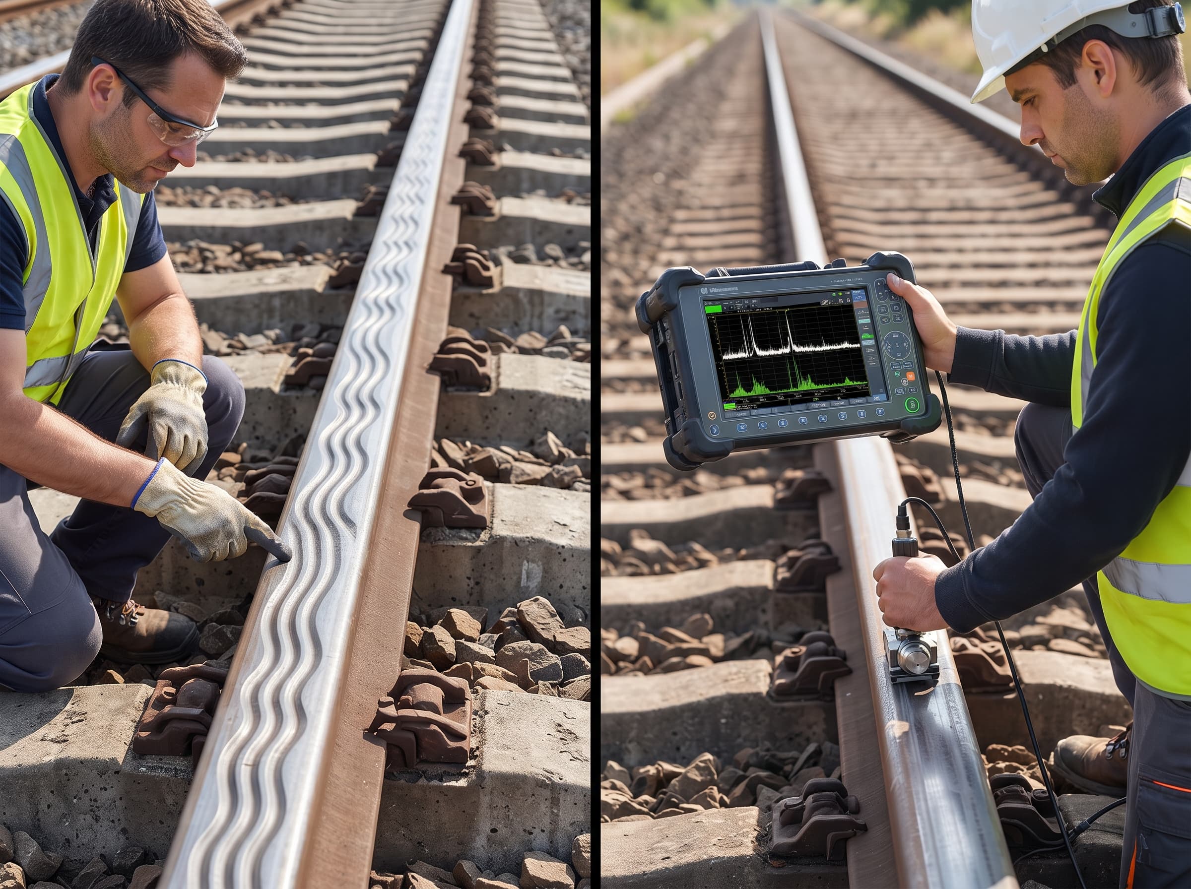
Corrugation on rail is a periodic, wave-like wear pattern on the rail running surface. Short-pitch corrugation typically repeats every 30 to 80 mm (about 1.2 to 3.1 in.) with peak-to-trough depths of 0.1 to 0.5 mm (0.004 to 0.020 in.). It is set by vehicle–track vibration, and its passing frequency follows f = v/λ.
Corrugation is a surface-geometry condition, not an internal flaw. FRA's own rail defect definitions in 49 CFR 213.113(d) exclude it from "flattened rail". It still matters to anyone responsible for internal rail testing, because a corrugated running surface is the surface every ultrasonic probe has to couple through.
This guide explains what causes corrugation, how it is measured and accepted after grinding, how to convert wavelength and speed into frequency, and what corrugation does to ultrasonic rail testing in the field.
What is corrugation on rail?
Corrugation on rail is a repeating pattern of peaks and troughs along the length of the rail head, with a fairly constant wavelength. It is described by its wavelength (crest-to-crest spacing), its depth or amplitude, and roughness measures such as RMS or peak-to-peak values.
A 2024 review in the MDPI journal Buildings (Wang et al.) gives the full range of observed rail corrugation as 20 to 1,200 mm (about 0.8 to 47 in.), exciting vibration from roughly 30 to 2,000 Hz. The same review defines short-wavelength corrugation as 30 to 80 mm long and 0.1 to 0.5 mm deep. On site it often shows as bright, polished crests and darker troughs on the running band.
How is corrugation different from other rail-head defects?
Corrugation on rail is often confused with other surface conditions. The difference matters, because each one is handled under a different rule or practice.
| Condition | What it looks like | Repeats at a regular spacing? | Where it sits in US practice |
|---|---|---|---|
| Corrugation | Wave pattern of crests and troughs along the running band | Yes, roughly constant wavelength | Surface geometry; treated by grinding. Not a 213.113 rail defect |
| Flattened rail | One short flattened length of the rail head | No | 213.113 defect when at least 3/8 in. deep and 8 in. or more long |
| Squat | A local dark depression, often with subsurface cracking | No | Surface-initiated RCF defect; can hide internal cracks |
| Head checks | Fine diagonal surface cracks on the gage corner | Loosely spaced, not a wave | RCF; see head checks and their risks |
| Shelling | Metal separating below the gage corner | No | Can mask internal defects from UT |
The FRA definition of flattened rail in 213.113(d)(9) draws the line explicitly:
"Flattened rail occurrences have no repetitive regularity and thus do not include corrugations, and have no apparent localized cause such as a weld or engine burn." (49 CFR 213.113(d)(9))
Key takeaway: corrugation on rail is identified by its regular spacing; a single depression is something else.
What causes rail corrugation?
Rail corrugation forms when a vibration mode of the wheel–track system fixes a wavelength, and a damage mechanism such as wear or plastic flow deepens it with every wheel pass. Researchers call these the wavelength-fixing mechanism and the damage mechanism, a framework set out by Grassie and summarized in both the MDPI review and the RailDamage overview.
Wheel–rail contact and creep
The wheel and rail touch over a patch roughly the size of a small coin. That patch carries the vertical wheel load and transmits traction, braking and curving forces. When creepage and friction vary as the wheel rolls over a small irregularity, the contact forces vary too. If those force variations repeat at a fixed spacing, wear or plastic deformation builds a repeating profile that grows with traffic.
Track dynamics and resonance
The rail, fasteners, pads, ties or slab and the wheelset all have their own stiffness, damping and natural frequencies. When the passing frequency of an initial roughness matches one of those frequencies, the system reinforces that wavelength.
A 2024 study in the Chinese Journal of Mechanical Engineering (Wang, Lei and Luo, Springer) measured a metro section on steel-spring floating-slab track with an actual operating speed of 99 km/h (61.5 mph). It found characteristic wavelengths of 34 mm (1.34 in.) on the inner rail and 59 mm (2.32 in.) on the outer rail. Finite element frequency-response models showed eigenfrequencies close to the measured passing frequencies. The authors attributed the inner-rail corrugation to third-order bending vibration of the wheelset and the outer-rail corrugation to lateral bending of the outer rail. On the long-sleeper embedded track they measured, the wavelengths were 46 mm and 47 mm.
The same study's conclusion on mitigation is specific: changing fastener and steel-spring stiffness "can shift the rail corrugation eigenfrequencies," which inhibits growth at the original wavelength. Other parameters only changed how fast the corrugation grew.
Support spacing
Support conditions can drive growth directly. The MDPI review summarizes an earlier test (Vadillo et al., Wear, 1998) in which corrugation reached 0.42 mm (0.017 in.) peak to peak after 920,000 wheelsets with 1,000 mm (about 39 in.) between sleepers. When intermediate sleepers cut the spacing to 500 mm (about 20 in.), corrugation growth stopped.
Rail steel and operating conditions
Head-hardened and wear-resistant rail can delay some forms of corrugation, but the RailDamage overview warns that reducing wear can raise the risk of rolling contact fatigue. Speed, axle load, curve radius, braking and traction all change the contact forces. Metro and light rail lines combine tight curves, frequent braking and uniform fleets running at similar speeds, which is why they report so much short-pitch corrugation.
Key takeaway: corrugation on rail is a system problem, so a lasting fix usually changes the system, not just the rail surface.
What types of rail corrugation are there?
Rail corrugation is classified by wavelength, by the mechanism that fixes the wavelength, and by the type of damage on the rail head. No single classification tells you the cause; a short wavelength can come from several mechanisms.
The MDPI review reproduces Grassie's six types, grouped by wavelength-fixing and damage mechanism:
| Type (Grassie) | Where it is reported | Damage mechanism (summary) |
|---|---|---|
| Heavy haul | Freight lines with high axle loads | Plastic deformation in the troughs |
| Light rail | Transit lines | Plastic bending of the rail |
| Booted (resilient) sleepers | Track on resilient tie boots (the review calls them elastic sleepers) | Wear at first, then plastic flow |
| Contact fatigue | Tangent and curved track | Rolling contact fatigue |
| Rutting | Mainly curves | Wear in the troughs |
| Roaring rails | Tangent and curved track | Wear in the troughs; the wavelength-fixing mechanism is listed as unknown |
The review's table is a summary of older literature, so treat the "where" column as typical, not exclusive.
The review also groups corrugation by what is happening to the rail head. Abrasion corrugation comes from uneven wear and is common on harder, heat-treated rail. Plastic-flow corrugation comes from uneven plastic deformation and is common under heavy loads. Hybrid corrugation shows both.
Key takeaway: record the wavelength, the location (inner or outer rail, curve or tangent) and the head appearance together, because the type is a diagnosis, not just a measurement.
How is corrugation on rail measured?
Corrugation on rail is measured by recording the longitudinal profile of the running surface and analyzing the repeating components in it, either directly (chord-based or inertial instruments) or indirectly (vehicle vibration or noise).
| Method | How it works | Speed range | Strengths | Limits |
|---|---|---|---|---|
| Hand-push trolley, inertial | An accelerometer or displacement sensor rides on the rail; the signal is integrated into a profile | Walking speed | High resolution; standard tool for acceptance work and diagnosis | Needs track time; short distances per shift |
| Hand-push trolley, chord-based | Laser or contact sensors measure offsets from a short chord; an inverse transfer function recovers the profile | Walking speed | Direct geometric measurement | Each chord layout has wavelengths it measures poorly; software must correct |
| Vehicle-mounted chord or inertial system | Sensors on a measuring car or grinding train | Up to about 12 mph (20 km/h) for one trolley-derived system; higher for dedicated cars | Covers long sections; repeatable runs for trend data | Must separate rail roughness from carbody and sensor motion |
| Axle-box or bogie acceleration | Accelerometers on in-service vehicles; the dominant frequency points to the wavelength | Line speed | Continuous monitoring without track access | Indirect; needs calibration against a direct measurement |
| Noise or sound-based | Microphones or in-car noise trending | Line speed | Cheap screening for "roaring" sections | Indirect; affected by wheels, track form and speed |
RailDamage, a site associated with the instrument maker RailTechnology GmbH, describes an inertial hand-push corrugation analysis trolley (CAT) that measures at walking speed and a higher-axle-load system that runs at up to 20 km/h (about 12 mph). Treat speed and accuracy figures from instrument makers as their published specifications, not independent test results.
Most measurement software reports roughness in wavelength bands, along with RMS, peak-to-peak and the dominant wavelength. Repeating the same measurement before and after grinding, and then at intervals, shows the growth rate. That trend is what predictive grinding is based on.
Key takeaway: a single measurement shows that corrugation is present; repeated measurements with the same method show whether it is accelerating.
Which standards cover corrugation measurement and grinding acceptance?
In the US, FRA's Track Safety Standards (49 CFR Part 213) set no corrugation limit; the published measurement and acceptance standards are European. In US practice, grinding acceptance is whatever the owner's grinding contract or specification says. AREMA's Manual for Railway Engineering (Chapter 4, Rail) may also be referenced; it is paywalled and not reproduced here. The European standards below are the published references for measurement and acceptance.
| Standard | Title (short) | What it is used for | Status (checked October 2026) |
|---|---|---|---|
| EN 13231-2:2020 | Acceptance of reprofiling rails in plain line, switches, crossings and expansion devices | Acceptance of rail grinding, milling and planing, including longitudinal (corrugation) and transverse profile | Current; replaced EN 13231-3:2012 |
| EN 13231-3:2012 | Acceptance of reprofiling rails in track | The older acceptance standard; two longitudinal and three transverse tolerance classes | Withdrawn by BSI on 24 Nov 2020. Contracts that still cite it should be updated |
| EN 13231-5:2018 | Procedures for rail reprofiling | Planning and carrying out reprofiling, including describing rail surface defects | Current |
| EN 15610:2019 (+A1:2025) | Rail and wheel roughness measurement related to noise generation | Direct measurement of acoustic roughness as one-third-octave spectra | Current, amended 2025. Does not cover grinding approval except where acoustic roughness is the criterion |
| EN ISO 3095 | Measurement of noise emitted by railbound vehicles | Vehicle pass-by noise type tests, run on a reference track whose rail roughness is controlled | The 2013 edition was replaced by a 2025 edition |
The numeric tolerance tables in these standards are paywalled. Use the edition named in your contract and read the limits from the purchased copy. Note that EN 13231 applies to Vignole (flat-bottom) rails of 46 kg/m and heavier, which covers most US rail sections from about 93 lb/yd upward.
Key takeaway: if a grinding specification cites EN 13231-3, it cites a withdrawn standard; ask for EN 13231-2:2020 or a stated in-house criterion.
Worked example: converting wavelength and speed to frequency
The passing frequency of corrugation on rail is f = v/λ: train speed divided by wavelength, in consistent units. In US units a convenient form is:
f (Hz) = 17.6 × speed (mph) ÷ wavelength (in.)
The factor 17.6 converts mph to inches per second (1 mph = 17.6 in./s).
Step 1: check the published metro case
The Springer study's section ran at 99 km/h. Converting: 99 ÷ 1.609 = 61.5 mph, which is 61.5 × 17.6 = 1,082 in./s (27.5 m/s).
| Rail | Wavelength | Calculation | Passing frequency |
|---|---|---|---|
| Inner | 34 mm = 1.34 in. | 1,082 ÷ 1.34 | ≈ 808 Hz (paper: about 809 Hz) |
| Outer | 59 mm = 2.32 in. | 1,082 ÷ 2.32 | ≈ 466 Hz (paper: about 466 Hz) |
The small difference on the inner rail is rounding in the unit conversion. The paper found a model eigenfrequency of 797 Hz close to the 809 Hz inner-rail passing frequency, which is how it linked that corrugation to wheelset bending.
Step 2: the same corrugation at different speeds
| Speed | Who runs at this speed | 1.34 in. corrugation | 2.32 in. corrugation |
|---|---|---|---|
| 2 mph | Hand-pushed UT cart or trolley | 26 Hz | 15 Hz |
| 10 mph | Slow test or measuring run | 131 Hz | 76 Hz |
| 35 mph | Light rail in street running | 460 Hz | 266 Hz |
| 61.5 mph | The measured metro section | 808 Hz | 466 Hz |
A wavelength fixed by a resonance near one frequency should change with speed. The fact that short-pitch corrugation often keeps a similar wavelength across a range of speeds is one reason its mechanism is still debated.
Step 3: work backward from a complaint
A transit agency logs a tonal noise near 500 Hz on a curve where trains run at 45 mph. The likely wavelength is λ = 17.6 × 45 ÷ 500 = 1.58 in. (about 40 mm). That points the measurement crew to short-pitch corrugation before they set up the trolley, and tells them which wavelength band to check in the report.
Key takeaway: frequency, speed and wavelength are linked by one line of arithmetic, so a noise or vibration complaint can be turned into a wavelength to look for.
How does corrugation on rail affect ultrasonic testing?
Corrugation on rail does not hide internal defects by itself, but it degrades the contact between the probe and the rail, which causes signal dropouts, extra noise and false calls, and can turn a test run into an invalid search. FRA report RR 22-36 (2022) lists acoustic coupling among the inherent limitations of conventional ultrasonic rail inspection and notes that poor coupling can weaken the signal reflected from a flaw.
Under 49 CFR 213.237, the test only counts if it is a valid search:
"Valid search means a continuous inspection for internal rail defects where the equipment performs as intended and equipment responses are interpreted by a qualified operator." (49 CFR 213.237(j))
Here is what corrugation does to each part of that definition in practice.
Couplant loss over the crests
Every rail UT system needs a liquid film between probe and rail, whether the probe is a fluid-filled wheel (roller search unit) or a sliding shoe. On corrugated rail the film thins over the crests and pools in the troughs. A 39 ft rail with 1.34 in. corrugation has about 349 crests (468 in. ÷ 1.34), and each crest is a chance for a momentary dropout. The symptom is a flickering or lost back-wall echo on the 0° channel and a drop in the noise floor on the angled channels. More on couplant choice and flow is in our guide to ultrasonic couplant for rail inspection.
Lift-off and probe rocking
A rigid sliding probe bridges the crests rather than following the troughs. When its footprint is close to the corrugation wavelength, it rocks. Rocking changes the beam's entry point and refracted angle slightly, so the amplitude of a real reflector can wander from pass to pass. A wheel probe follows the surface better, but at speed it can bounce, especially when the passing frequency approaches a carriage or suspension resonance.
False calls
Corrugation produces two kinds of false indication:
- Loss of back-wall echo (LOBW) on the 0° channel that looks like the signature of a horizontal split head or another reflector that blocks the beam. A loss that repeats at the corrugation pitch, on both rails or across a long section, is a coupling problem, not a flaw.
- Surface and near-surface noise on the angled channels, especially at the front of the gate, where the crests act as small reflectors. These can trigger alarms on systems with automated gating.
A practical check: if indications repeat at the same spacing as the measured corrugation, treat them as geometric until proven otherwise. Our guide to false calls in rail UT covers how to separate geometric, coupling and contamination causes from real defects.
Missed defects
The opposite risk is more serious. If sensitivity drops on every crest, a real transverse defect that sits under a poorly coupled stretch may give a weak or no response. This is why a run with sustained coupling loss should be logged as not searched rather than accepted as clean.
| Symptom on the display | Likely cause on corrugated rail | Field response |
|---|---|---|
| 0° back-wall flickers at a regular spacing | Couplant film breaking over crests | Increase couplant flow, slow down, re-run |
| Sustained LOBW over a long stretch | Lift-off or bounce, or very deep corrugation | Mark as not searched; hand-test with a contact probe |
| Noise at the start of the angled gate | Crest reflections | Check gate start, confirm on a reference standard |
| Amplitude of a known reflector varies pass to pass | Probe rocking, entry-point shift | Hand prove-up with a contact probe from both directions |
| Repeated alarms at the corrugation pitch | Geometric indications | Compare spacing with measured wavelength before calling a defect |
Key takeaway: on corrugated rail, the main UT risk is not a false call; it is accepting a run as a valid search when coupling was lost.
How should a UT crew handle corrugated rail?
On corrugated rail, a UT crew should confirm coupling before trusting the data, slow down, prove up every suspect by hand, and record any track that could not be validly searched. These steps apply to hand-pushed carts as much as to rail-bound test vehicles.
- Ask for surface data before mobilizing. Corrugation reports, grinding history and noise complaints show where coupling will be poor. On transit systems, short-pitch corrugation on curves is common.
- Check probe condition and set-up for the surface. For wheel probes, check tire condition and fluid fill as specified by the manufacturer. For sliding probes, a shoe contoured to the rail head and a steady couplant feed help it ride the crests.
- Slow down. Lower speed reduces bounce and gives the couplant time to fill the troughs. On a hand cart, a steady walking pace is better than stop-start pushing.
- Increase couplant flow through corrugated stretches, within what the system and track conditions allow, and watch the 0° back-wall echo as the coupling monitor.
- Verify sensitivity on a reference standard before and after the corrugated section, so a drop in response can be traced to the rail, not the instrument.
- Prove up every suspect by hand with a contact probe from both directions, after cleaning the spot. Hand testing is slower but takes the moving probe out of the equation.
- Record what was not searched. Under 213.237(g), rail that could not be validly searched is not counted as inspected. Under 213.237(h), the track owner must re-search it, reduce speed to no more than 25 mph, or replace the rail before the inspection interval runs out. 49 CFR 213.241 requires the inspection record to show untested track.
- Coordinate with grinding. Grinding removes corrugation and improves coupling, but grinding trains can also leave their own periodic marks. The MDPI review cites a study in which a grinding train at 12 to 13 km/h (about 7.5 to 8 mph) left marks about 60 mm (2.4 in.) long. See our guide to rail grinding and ultrasonic testing for test timing around a grinding program.
Hand-pushed carts are often the right tool for short, heavily corrugated sections, crossings and curves on transit lines, because the operator can watch the display and stop. Our comparison of a hi-rail truck and an inspection cart covers when each fits.
Key takeaway: a slower, documented test on corrugated rail is worth more than a fast run with silent dropouts.
How is corrugation treated?
Rail grinding is the most widely used treatment for corrugation on rail, but it removes the symptom; changes to the track or vehicle system address the cause. The RailDamage overview describes grinding as the most effective current method and notes that it can be corrective, preventive or predictive.
| Treatment | What it changes | Notes |
|---|---|---|
| Corrective grinding | Removes existing corrugation | Corrugation can return if the wavelength-fixing mechanism is unchanged |
| Preventive or cyclic grinding | Removes metal at intervals before corrugation deepens | Also removes surface RCF; grinding acceptance is checked by measurement |
| Friction management | Changes the creep conditions at the contact | Friction modifiers can help some types; effects vary by site |
| Fastener and pad stiffness changes | Shifts system eigenfrequencies | Shown in modeling to suppress growth at the original wavelength (Springer, 2024) |
| Rail dampers | Adds damping in a frequency range | Effective only if tuned to the site's frequency |
| Rail steel selection | Changes wear resistance | Harder rail may trade wear for RCF risk |
| Support spacing | Changes the support resonance | Closer sleepers stopped growth in the Vadillo test |
Grinding also matters for internal testing. Corrugation and RCF damage on the head are the conditions that degrade coupling and mask defects, so testing soon after a grinding pass usually gives cleaner data. Our guide to rolling contact fatigue in rail explains why surface fatigue and internal defects are linked.
Key takeaway: if corrugation returns at the same wavelength after grinding, look at the track and vehicle system, not the grinder.
What are the limits of corrugation measurement and UT?
Neither corrugation measurement nor ultrasonic testing gives the whole picture on its own, and each has limits that a track owner should know.
- Profile measurement sees only the surface. A clean corrugation report says nothing about transverse defects, vertical split heads or bolt hole cracks. Internal testing is still required under 213.237.
- UT does not measure corrugation. A loss of coupling can suggest corrugation, but UT data cannot give its wavelength or depth.
- Indirect methods need calibration. Axle-box and noise measurements infer the wavelength. They should be checked against a direct trolley measurement before they drive grinding decisions.
- Chord-based systems have blind wavelengths. Each chord geometry has wavelengths it measures poorly; the software correction depends on the instrument.
- Research results are site-specific. The 34 mm and 59 mm wavelengths and their mechanisms apply to the section studied. Other lines can form corrugation at similar wavelengths through different mechanisms.
- Masking still applies. Shelling and other surface defects can block the beam even where corrugation is light.
- This article does not give numeric acceptance tolerances. EN 13231-2 and EN 15610 limits are in the purchased standards, and owner-specific limits are in the grinding contract.
How EMA Industries applies this
EMA Industries provides ultrasonic rail flaw testing for transit agencies, short lines and industrial track owners, working from Southern California and mobilizing nationwide. On corrugated rail, the job is to keep the search valid: watch coupling, slow down where needed, prove up suspects by hand and report any track that could not be searched, so the owner can act under 213.237(h). If your line has known corrugation or a grinding program coming up, contact EMA Industries to plan test timing around it.
Related reading: how ultrasonic testing works for railways, ultrasonic rail testing for metro and light rail systems, railway track defects and detection methods and rail predictive maintenance.
Frequently asked questions
What causes corrugation on rail?
Corrugation forms when a vibration mode of the wheel–track system fixes a wavelength and wear or plastic deformation deepens it with each wheel pass. Track stiffness, fastener and pad properties, support spacing, curve radius, speed, axle load, friction and rail hardness all affect which wavelength forms and how fast it grows.
Is corrugation on rail an FRA rail defect?
No. Corrugation is not one of the defects listed in the 49 CFR 213.113 remedial action table, and the FRA definition of flattened rail in 213.113(d)(9) specifically excludes corrugations. Part 213 sets no corrugation depth limit. Owners control it through their own maintenance and grinding standards.
How is corrugation on rail measured?
The most direct method is a hand-pushed trolley that records the longitudinal profile of the running surface, using inertial or chord-based sensors. Vehicle-mounted systems cover longer distances, and axle-box acceleration or noise trending can flag sections for follow-up. Grinding acceptance is commonly checked against EN 13231-2:2020 or an owner's contract criterion.
Which defects does ultrasonic rail testing find?
Ultrasonic rail testing looks for internal defects such as transverse fissures, detail fractures, compound fissures, vertical and horizontal split heads, and bolt hole cracks. It does not measure surface geometry such as corrugation or wear. Surface conditions do affect how well the probes couple, which is why corrugation matters to a valid search. See our guide to FRA defect codes for how each defect is handled.
How do you remove corrugation from rail?
Rail grinding (or milling) removes corrugation by restoring the longitudinal profile, and the result is checked by measuring the profile after the pass. If the corrugation returns at the same wavelength, the cause is usually in the track or vehicle dynamics, and changes such as fastener stiffness, rail dampers, friction management or support spacing may be needed.
What is the difference between a squat and corrugation?
A squat is a single, localized depression on the running surface, usually associated with rolling contact fatigue, and it can hide subsurface cracks that need ultrasonic follow-up. Corrugation is a repeating wave pattern along a length of rail. A squat is a defect in its own right; corrugation is a surface-geometry condition.
Sources
- 49 CFR 213.113, Defective rails, including the (d)(9) flattened rail definition. eCFR; text checked in the 2024 CFR on govinfo
- 49 CFR 213.237, Inspection of rail (valid search, untested rail options). eCFR
- 49 CFR 213.241, Inspection records. eCFR
- Wang, Z., Lei, Z., Luo, Y. et al., "Cause Analysis of Rail Corrugation in Metro Lines Based on System Vibration Characteristics," Chinese Journal of Mechanical Engineering 37, 147 (2024). Springer Open, doi:10.1186/s10033-024-01151-0
- Wang, Q.-A. et al., "Concise Historic Overview of Rail Corrugation Studies: From Formation Mechanisms to Detection Methods," Buildings 14(4), 968 (2024). MDPI, doi:10.3390/buildings14040968
- RailDamage, "Corrugation" (22 May 2024), associated with RailTechnology GmbH. raildamage.com
- FRA, Expansion of the Rail Flaw Library at the Transportation Technology Center, RR 22-36 (November 2022). FRA eLibrary
- BS EN 13231-3:2012, Acceptance of reprofiling rails in track (withdrawn 24 Nov 2020). BSI Knowledge
- EN 13231-2:2020, Acceptance of reprofiling rails in plain line, switches, crossings and expansion devices. EVS catalog
- EN 13231-5:2018, Procedures for rail reprofiling. EVS catalog
- EN 15610:2019, Rail and wheel roughness measurement related to noise generation. SIS catalog
- EN ISO 3095:2013, Measurement of noise emitted by railbound vehicles (replaced by the 2025 edition). EVS catalog