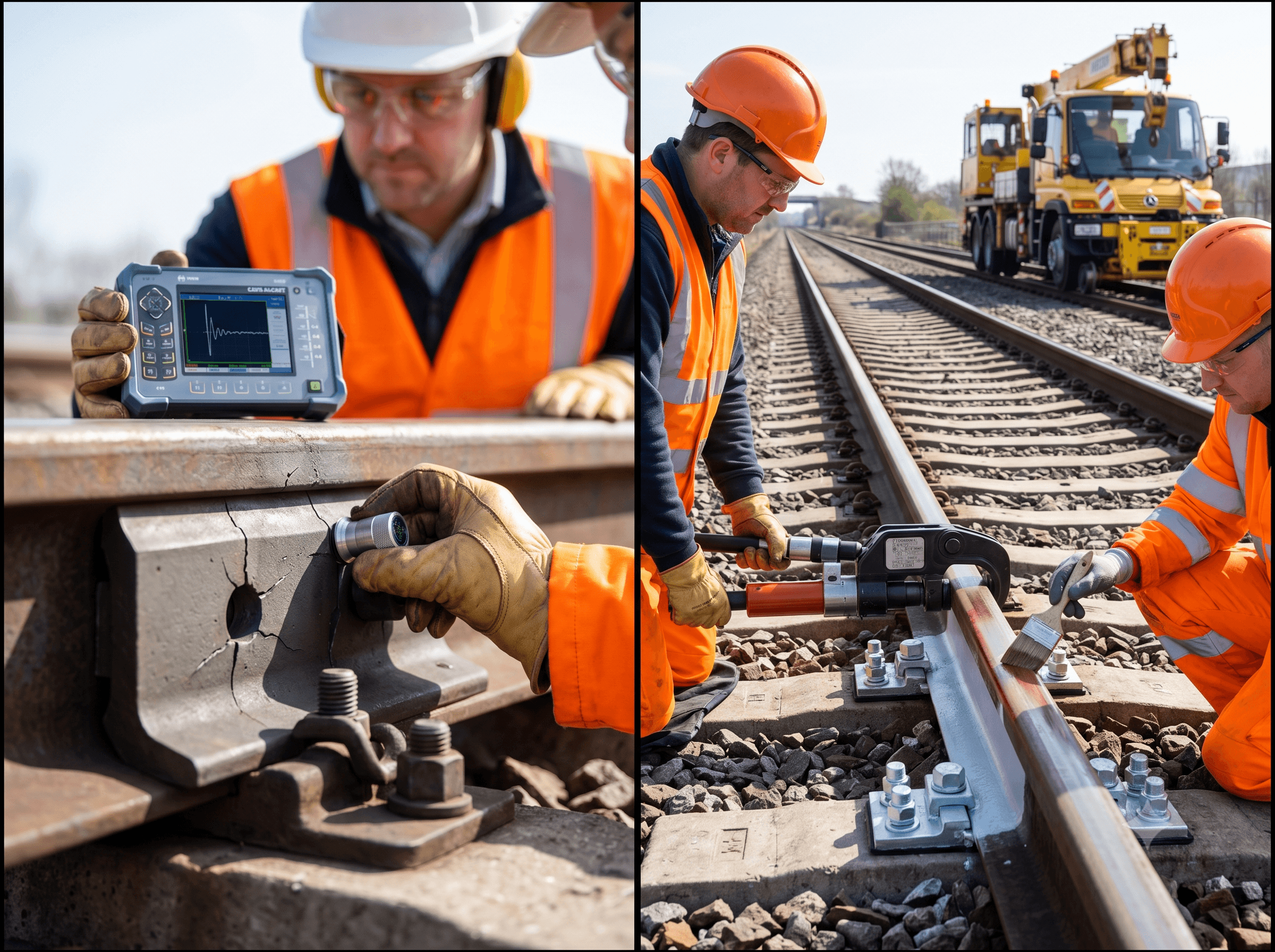
Bolt hole cracks are fatigue cracks that start at a bolt hole in a rail joint and run across the web toward the head or the base, as defined in 49 CFR 213.113(d)(1). Under the 213.113 table, a crack over 1/2 inch brings a 50 mph limit and reinspection, and one over 1-1/2 inches limits speed to 30 mph.
The crack sits behind the joint bars, so a track inspector walking the line can't see it until it is far along. Ultrasonic testing (UT) finds it with the bars in place. This guide covers what the rule says, why the cracks form, how angle-beam and straight-beam UT find them, what the owner must do once one is found, and how good drilling and joint maintenance keep them from starting.
It is about the crack in the rail. Cracks in the joint bars themselves, and insulated joints, have their own guides, linked below.
What is a bolt hole crack under 49 CFR 213.113?
A bolt hole crack is a crack across the rail web that starts at a bolt hole and climbs toward the head or drops toward the base. FRA defines it in 49 CFR 213.113(d)(1):
"Bolt hole crack means a crack across the web, originating from a bolt hole, and progressing on a path either inclined upward toward the rail head or inclined downward toward the base. Fully developed bolt hole cracks may continue horizontally along the head/web or base/web fillet, or they may progress into and through the head or base to separate a piece of the rail end from the rail."
The same paragraph sets two counting rules that matter for records and remedial action:
- Several cracks in one rail end count as one defect. A rail end with an upper and a lower crack from the same hole, or cracks at two of its holes, is reported once.
- Cracks in the two rail ends of one joint are separate defects. If both the leaving and the receiving rail are cracked, the owner has two defects, each with its own size and remedial action.
The definition describes a progression. The crack starts small at the hole wall, grows on an incline through the web, and once it reaches a fillet it can turn along the head or base. At the last stage it can break out a wedge of the rail end. That last stage is the "break out in rail head" row of the remedial action table, which carries the most restrictive action.
Key takeaway: the defect is in the rail web at the hole, not in the joint bar. Cracked bars fall under 213.121.
Why do bolt hole cracks form at rail joints?
Bolt hole cracks are fatigue cracks driven by the stress concentration of the hole and by wheel impact at the joint. FRA-sponsored research named this as the main way bolted joints fail more than 40 years ago. The 1980 report Sleeve Expansion of Bolt Holes in Railroad Rail (Lindh, Taylor and Rose, FRA/ORD-80/5) opens its abstract with: "The most predominant failure mode of rails with bolt joints is a web crack initiating at the rail bolt hole." It adds that the failure is "of a classical fatigue nature induced by web stress concentration around the bolt hole" (ROSA P record).
Four causes work together.
Stress concentration at the hole
A hole in a loaded plate raises the local stress at its edge well above the stress in the plate around it. In the rail web, that edge is where every passing wheel's shear and bending stress peaks. A 2016 finite element study from the University of Illinois RailTEC group (Zhu, Edwards, Qian and Andrawes, Transportation Research Record 2545) summarizes earlier research this way: the primary driving force for bolt hole cracks in jointed track is "the positive shear stress around the bolt hole", which is proportional to the wheel-rail impact load and is magnified by the stress concentration of the hole (RailTEC PDF).
Impact at the rail gap
A joint is a discontinuity. The rail gap, any height mismatch between the rail ends and the dip of a sagging joint all make the wheel strike the receiving rail. The joint bars are also less stiff in bending than the rail they replace. Zhu and co-authors point to these geometric and stiffness steps, and the impact loads they cause, as the main reason defects start at joints. Their model also found that the two center bolts, nearest the rail ends, have the most effect on stress at the rail end.
A TTCI test at the Facility for the Accelerated Service Testing (FAST) shows the same mechanism in special trackwork. In a high-angle crossing diamond, ultrasonic testing found rail cracks at three of 16 three-bolt connections after about 100 MGT. Four of the crack starts were at bolt holes, and TTCI wrote that these were "directly related to contact with the bolts, where the walls of the holes are subjected to vertical wheel impact forces and longitudinal rail stress" (TTCI TD-17-027, October 2017).
Temperature force in CWR joints
In continuous welded rail (CWR), a bolted joint also carries the rail's thermal force. When the rail is colder than its neutral temperature it pulls apart at the joint, and the bolts bear on the hole walls. Zhu and co-authors note that bolt hole cracks in temporary CWR joints "are typically generated by thermal-induced longitudinal stresses". That is one reason 213.119 asks for extra bolts, anchoring or welding at CWR joints (see the rules section below).
Hole quality: drilling, burrs, chamfers and torch cuts
The hole itself can start the crack. A 1952 AREA fatigue study of 132 lb RE and 140 lb PS rail tested holes with drill gouges, burrs and a rail brand at the hole edge. Its abstract reports that "a bolt hole drilled with a dull or improperly sharpened drill through a brand reduces the fatigue life of the rail by 50 percent" (AREA Bulletin 56, no. 521, 1952; TRID record). This is why drilling practice calls for sharp tools, correct hole size and location, and removal of the edge burr by chamfering.
A torch-cut or burned hole is worse still. Flame cutting leaves a rough, heat-affected wall with a hard, brittle edge layer. 49 CFR 213.121(g) bans them: "No rail shall have a bolt hole which is torch cut or burned in Classes 2 through 5 track."
Key takeaway: every bolt hole is a fatigue site. Impact, loose bolts, CWR tension and a poor hole surface decide how fast a crack starts there.
Where do the cracks start, and which way do they run?
Most bolt hole cracks start at the hole nearest the rail end and run at roughly 45° through the web. Zhu and co-authors, citing earlier work, state that bolt hole cracks typically start "at the bolt hole on the very end of the receiving rail" at a direction "approximately 45°" to the rail's neutral axis. Field people often call a hole with cracks in several directions a "star crack".
The orientation matters because UT finds a planar crack best when the beam strikes the crack face at a right angle. A crack inclined at 45° in the vertical plane of the web is face-on to a 45° beam travelling in one direction, and nearly edge-on to the same beam travelling the other way.
| Crack path from the hole | Where it goes if it keeps growing | Beam that meets it face-on (typical) |
|---|---|---|
| Upward toward the rail end | Into the head/web fillet, then along the head or into the head | 45° probe looking toward the rail end from behind the hole |
| Upward away from the rail end | Same, on the far side of the hole | 45° probe facing the other way |
| Downward toward the rail end | Base/web fillet, then along or through the base | 45° probe from the far side of the joint gap, which sound can't reach (see the worked example) |
| Downward away from the rail end | Base/web fillet on the far side | 45° probe facing the rail end |
| Steeper paths | Same | 37–38° web probes |
| Any crack that changes the hole outline | 0° beam: changed top-of-hole or base echo |
Probe angles are a typical arrangement, not a rule. Part 213 names no UT method or angle, and systems differ by maker and owner procedure.
How does ultrasonic testing find bolt hole cracks?
UT finds bolt hole cracks with web-directed angle beams, usually 37° to 45°, looking both ways along the rail, plus a 0° straight beam over the hole. All of them enter through the rail head, so the joint bars don't need to come off. That matters, because 213.237(f) requires that "Inspection equipment shall be capable of detecting defects between joint bars, in the area enclosed by joint bars."
The angle beams
A test car or cart typically carries 0°, 70° and one or more mid-angle channels in fluid-filled wheels or sleds. The 70° beams are aimed at transverse defects in the head. They are the wrong tool for a web crack, because a 70° beam entering the head runs almost flat and leaves the head long before it reaches the bolt-hole depth.
The web channels do that job. A rail testing patent (US 5,777,891, filed 1996, published 1998) describes "a beam of 45 degrees from the vertical" that "detects cracks which propagate from bolt holes", and a 38° beam that "is mainly used to test the web area of the rail for cracked bolt holes". Many systems use 37° or 38° channels for steeper paths and 45° channels for the classic 45° crack, each mounted forward and backward. A 1999 Mountain-Plains Consortium review of North American test cars listed 0°, 45° and 70° transducers plus a side-looker, with the 45° and 70° mounted forward and reverse (MPC 99-106, Upper Great Plains Transportation Institute). Wheel probes typically run near 2.25 MHz.
The 0° beam
The straight beam checks the rail height and sees the top of each hole as it passes. On 136RE rail, the top of a 1-1/4 inch hole lies about 3.59 inches below the running surface, so its 0° echo comes back at about 31 µs, against about 63 µs for the base. The same patent describes the 0° beam's use "for detecting cracked or elongated bolt holes". A crack that widens the hole outline, or a crack running down toward the base, can lengthen the hole echo or cut the base echo beside the hole.
Telling a crack from the hole
Every bolt hole gives an echo, so the operator is looking for a change in an expected pattern. TTCI describes it plainly: "A trained operator learns to discern the difference between defects and normal features such as bolt holes and welds" (TTCI TD-16-030, July 2016). In practice that means comparing each hole with its neighbors and with the same hole from the other direction. A crack shows as an extra echo that keeps responding after the probe has passed the point where the plain hole echo peaks. On a test car, a suspect at a joint is then confirmed by hand with a contact angle-beam probe before it is classed, sized and marked.
Key takeaway: bolt hole cracks are a web job for 37–45° beams in both directions, backed by the 0° beam, and every suspect is checked against the normal hole signature before it is called.
Worked example: where the probe must be to hit a 45° crack
On 136RE rail, a 45° beam meets an upward 45° crack face-on only when the probe is about 1.2 to 3.3 inches behind the hole centerline, for the first 1-1/2 inches of crack. This example shows why systems need beams in both directions, and why some cracks can't be reached from their own rail.
Inputs (nominal, from supplier drawings): 136RE rail height 7-5/16 in.; bolt-hole center 3-3/32 in. above the base, so 4.219 in. below the running surface; hole diameter 1-1/4 in. (radius 0.625 in.); first hole 3-1/2 in. from the rail end. Shear velocity 0.1280 in./µs. The crack runs from the hole edge at 45°, upward toward the rail end. Wedge and wheel delay, beam spread and probe footprint are ignored.
Geometry. A crack at 45° is face-on to a beam travelling at 45° the other way, down and toward the rail end. So the probe must sit behind the hole (away from the rail end) and look toward it. For a point on the crack at depth y, the probe sits y inches back from that point, and the sound path is y × √2.
| Point on the crack | Probe position behind the hole centerline | Depth of the point | Sound path | Round-trip time |
|---|---|---|---|---|
| Crack root at the hole edge | 3.34 in. | 3.78 in. | 5.34 in. | 83.5 µs |
| 0.25 in. up the crack | 2.98 in. | 3.60 in. | 5.09 in. | 79.6 µs |
| 0.50 in. up the crack | 2.63 in. | 3.42 in. | 4.84 in. | 75.6 µs |
| 1.00 in. up the crack | 1.92 in. | 3.07 in. | 4.34 in. | 67.8 µs |
| 1.50 in. up the crack | 1.21 in. | 2.72 in. | 3.84 in. | 60.0 µs |
What the operator sees. The plain hole gives its strongest 45° echo with the probe 4.22 in. behind the centerline, from the hole's near wall at a 5.34 in. sound path (83.5 µs). A cracked hole keeps answering as the probe moves closer. The echo walks in to shorter sound paths: about 0.5 in. shorter for every 0.5 in. of crack. A 1-inch crack keeps its echo over about 1.41 in. of probe travel (crack length × √2), from 3.34 to 1.92 in. behind the hole.
Sizing check. If that travel span were measured as 1.41 in., the crack would be about 1.0 in., right on the boundary between the 1/2–1 in. and 1–1-1/2 in. rows of the remedial action table. Beam spread lengthens the apparent span, so the result depends on the sizing method (for example a 6 dB drop from the peak), which the procedure and the record should state.
The crack the beam can't reach. Now take a crack running downward toward the rail end from the same end hole. The beam that meets it face-on travels down and away from the rail end, so the probe must sit on the rail-end side of the hole: about 5.1 in. from the hole centerline for the crack root and 6.5 in. for a point 1 in. along. The hole is only 3.5 in. from the rail end, so those positions are 1.6 to 3.0 in. past the end of the rail, across the joint gap. Sound doesn't cross the gap. That crack has to be found indirectly: by the other beams (edge-on response, tip diffraction), by the 0° hole and base echoes, or by hand probing with other angles.
Depth check. The crack root at 3.78 in. depth lies inside the web (the head underside is about 1.94 in. down and the base starts about 6.13 in. down). An upward crack would run about 2.6 in. along its path before reaching the head fillet, about 2.3 in. toward the rail end, still short of the end at 3.5 in.
Key takeaway: each crack direction needs its own beam direction, and at the end hole some face-on positions fall off the rail. That is why one pass in one direction is not a full test of a joint.
What limits UT at the joint bars?
UT tests the rail inside the joint, but the joint itself blocks some beam positions, hides the crack from the eye and leaves the bars untested. These are the main limits.
- The rail gap cuts off probe positions. As the worked example shows, some face-on positions for end-hole cracks fall past the rail end. A test car moving through a joint also has a few inches where its wheel probes straddle the gap.
- Detection rates for small cracks are poorly known. In a 1998 TTCI benchmark of six hi-rail systems, bolt hole cracks were the worst-detected flaw type, at 33% (TTCI TD-99-006, Garcia and Reiff, 1999). That figure rests on only two cracks, 0.25 and 0.38 in. long, so it can't be read as a rate. The 1999 MPC 99-106 review listed both as "frequently missed" on the test track. The honest reading is that cracks well under 1/2 inch are hard to find reliably.
- Joint bars cover the crack. A visual inspection under 49 CFR 213.233 usually sees a bolt hole crack only once it reaches the edge of the bar, the fillet or the base. Rust streaks or a dropped rail end can be clues, but they come late.
- The bars themselves aren't tested. A rail flaw test examines the rail. A cracked joint bar is a 213.121 condition that needs a close on-foot check or dedicated joint-bar UT, covered in our guide to rail joint inspection.
- Coupling and surface condition. Batter, chipped rail ends and dirt at the joint can weaken coupling just where the beams need to enter. If a valid search couldn't be made, the stretch counts as untested under 213.237(g), not as clean rail.
- Insulated joints. The end post and insulation add their own failure modes and signal issues. See our guide to insulated rail joint inspection.
Key takeaway: treat every joint as a place where coverage is partial, and plan hand verification and follow-up there.
What remedial action does 213.113 require for bolt hole cracks?
The remedial action depends on crack length: over 1/2 to 1 inch means 50 mph and reinspection in 90 days, over 1 to 1-1/2 inches means 50 mph and reinspection in 30 days, over 1-1/2 inches means 30 mph, and a break out in the head needs a person to supervise each move. The rows below were read from the remedial action table in the 2014 final rule, because Cornell LII and eCFR show the table as an image (79 FR 4256, January 24, 2014). The table has not changed since 2014.
| Bolt hole crack length | Remedial action | What the notes require |
|---|---|---|
| 1/2 in. or less | None prescribed | The table's bolt hole crack rows start at "more than 1/2" in. |
| More than 1/2 in., not more than 1 in. | H and F | H: 50 mph or the class maximum, whichever is lower. F: reinspect within 90 days |
| More than 1 in., not more than 1-1/2 in. | H and G | H: 50 mph. G: reinspect within 30 days |
| More than 1-1/2 in. | B | No more than 30 mph or the class maximum, as authorized by a 213.7(a) person with at least one year of supervisory experience |
| Break out in rail head | A | A 213.7 designated person visually supervises each operation over the defective rail |
Source: 49 CFR 213.113(c), remedial action table and notes.
Four points from the rest of 213.113 shape what happens on the ground:
- Verify fast. Under 213.113(b), an indication must be verified within four hours, or immediately when it suggests a defect needing action A, A2 or B. A suspect bolt hole crack longer than 1-1/2 inches falls in that group.
- A designated person decides. Under 213.113(a), a person designated under 213.7 decides whether the track may stay in use. The test operator finds and sizes the crack; the designated person disposes of it.
- Reinspection repeats. Under notes F and G the 90- or 30-day cycle starts over at each reinspection until the rail is replaced or repaired, or the crack grows into a more restrictive row. A missed reinspection drops the speed to Class 2 or the class maximum, whichever is lower.
- Count and record correctly. One rail end is one defect; two cracked rail ends in a joint are two. The 213.241 record must give each defect's location, type and size if it isn't removed before the next train.
Note A is not a stop order. It sets no speed, but each move needs a person watching the rail. Replacing the rail end removes the defect entirely, and most owners do that rather than manage a growing crack for months.
Worked example: three cracks, one joint
A Class 4 freight line (maximum 60 mph) is tested on a Monday. At one joint the operator verifies a 3/4-inch crack in the receiving rail's end hole and a 1-3/8-inch crack in the leaving rail's end hole. A second joint has a 3/8-inch crack.
| Defect | Length | Row | Action |
|---|---|---|---|
| Joint 1, receiving rail | 3/4 in. | >1/2–1 | H and F: 50 mph; reinspect by day 90 |
| Joint 1, leaving rail | 1-3/8 in. | >1–1-1/2 | H and G: 50 mph; reinspect by day 30 |
| Joint 2 | 3/8 in. | none | No prescribed action; record it and watch it |
The two cracks at joint 1 are two defects, and the 30-day reinspection governs the joint in practice. The speed over joint 1 drops from 60 to 50 mph. If the leaving-rail crack is found at more than 1-1/2 inches at reinspection, the action becomes B and the speed no more than 30 mph. More on the lettered actions is in our guide to FRA defect codes.
What do 213.121 and 213.119 require at the joint?
213.121 sets the rules for every bolted joint, and 213.119 adds bolting, repair and inspection duties for joints in CWR. Together they control most of the conditions that start bolt hole cracks.
| Rule | Requirement | Link to bolt hole cracks |
|---|---|---|
| 213.121(a) | Each rail joint, insulated joint and compromise joint of structurally sound design and dimensions for the rail | Wrong or worn bars let the joint work and raise impact |
| 213.121(b) | Class 3–5: replace a bar that is cracked, broken or worn enough to allow excessive vertical rail movement with all bolts tight | Vertical movement loads the hole walls |
| 213.121(c) | Any class: replace a bar cracked or broken between the middle two bolt holes | A failed bar transfers load to the rail ends |
| 213.121(d) | Jointed track: at least two bolts per rail at each joint on Class 2–5, one on Class 1 | Missing bolts change stress at the remaining holes |
| 213.121(e) | CWR: at least two bolts per rail at each joint | Same |
| 213.121(f) | Bolts tight enough to support the rail ends firmly but allow expansion and contraction; no-slip joints over 400 ft are treated as CWR | The tension balance discussed under prevention |
| 213.121(g) | No torch-cut or burned bolt holes on Class 2–5 | Removes the worst hole condition |
| 213.121(h) | No joint bar reconfigured by torch cutting on Class 3–5 | |
| 213.115 | Rail end mismatch limits, for example 1/8 in. on tread and gage side for Class 4–5 | Mismatch drives wheel impact at the receiving rail |
49 CFR 213.119 requires each CWR plan to cover joints:
- 213.119(c)(1)–(2): at least two bolts per rail at each CWR joint. A bolted joint installed during CWR installation after October 21, 2009 must, within 60 days, be welded, given six bolts, or have every tie anchored 195 feet in both directions.
- 213.119(c)(3): a CWR joint with a service failure or a failed bar and a rail gap must be welded, or rebuilt with new bars and bolts plus one of several follow-ups (weld within 30 days, an extra bolt per rail end, 195 ft of anchoring, or added rail).
- 213.119(h): written procedures for inspecting CWR joints, including periodic on-foot inspections. Inspectors must look at least for loose, bent or missing bolts, rail end batter or mismatch, and signs of excessive longitudinal rail movement. Cracked bars are handled under 213.121.
- 213.119(h)(6): minimum CWR joint inspections per calendar year, set by class, traffic type and tonnage. They range from none on Class 1 track to four a year on the busiest Class 4 and 5 lines, with set spacing: 4 a year at least 60 days apart, 3 at least 90, 2 at least 120, 1 at least 180.
These on-foot inspections look at the joint from outside. They are not a test for bolt hole cracks, which still comes from the 213.237 rail flaw test. The CWR side is covered in more depth in our guide to continuous welded rail, and joint types in our guide to rail joints.
How can bolt hole cracks be prevented?
Prevention comes down to three things: a good hole, the right bolt tension and a joint that doesn't take impact. The most complete answer is to remove the joint by welding it out. Where joints stay, these practices lower the risk.
1. Drill a good hole
- Drill, don't burn. Torch-cut holes are illegal on Class 2–5 track under 213.121(g). In the 2014 rule FRA noted that such holes "are easily identifiable through the rail flaw detection technology currently in use".
- Use sharp tools and chamfer the edges. The 1952 AREA tests found a dull drill through a brand halved fatigue life. Removing the drill burr with a chamfer takes away the sharpest edge defect. The 2016 Zhu paper summarizes the AREMA Manual for Railway Engineering as recommending "proper hole drilling and dressing" to prevent uneven stress around the hole. AREMA MRE Chapter 4 has a section titled Rail Drillings, Bar Punchings and Bolts. Check the current edition for its details, which aren't public.
- Put the hole in the right place. Use the standard drilling for the section (for 136RE, holes 3-1/2 in. and then 6 in. apart from the rail end on a supplier drawing). Drill at the right height, and don't drill through the brand.
- Consider cold expansion. Cold expansion squeezes the hole wall past yield so it is left in residual compression. The 1980 FRA study found "a factor of 10 or greater improvement in rail life due to reduction in bolt-hole failure could be anticipated" from laboratory fatigue tests, with an 8.5-mile field trial then still under evaluation. More recent work, such as Pucillo and co-authors' 2021 International Journal of Fatigue paper (doi:10.1016/j.ijfatigue.2021.106275), models the process for rail-end bolt holes. Treat the factor-of-10 figure as a 1980 laboratory projection, not a field result.
2. Keep bolt tension right
Bolt tension has a trade-off. In the Zhu model of a 115RE joint, raising bolt load reduced rail-end deflection and stress at the upper fillet, but increased the stress at the rail-end bolt hole. Loose bolts are worse overall: they let the joint work, which raises impact and allows head-web cracking near the rail end. AREMA MRE Chapter 5 has a section titled Track Bolt Tension Practice for the target values. The practical rule is to tighten to the owner's specified tension and recheck after the joint has seated, not "as tight as possible".
3. Maintain the joint
The Zhu paper also summarizes AREMA's other measures: regular surfacing and track maintenance to prevent excessive vertical deflection at the joint, properly fitting bars, tight bolts and adjusted rail restraints to prevent longitudinal stress. In field terms:
- Keep the joint surfaced and the ties under it sound, so the joint doesn't pump.
- Correct rail end batter and mismatch before they exceed 213.115, by grinding or welding.
- Replace worn bars, which let the rail ends move vertically under 213.121(b).
- In CWR, keep anchors and rail neutral temperature in order so the joint isn't loaded in tension. Weld out joints wherever the plan allows.
- Follow up known small cracks. A 3/8-inch crack has no prescribed action, but it will grow.
Lubrication does not stop a bolt hole crack once it has started, and no current method removes the risk while the hole is there. Only removing the cracked rail end, or the joint itself, ends it.
How often do bolt hole cracks cause train accidents?
FRA accident data list a bolt hole crack or break (cause code T201) as the primary cause of 64 reported train accidents from 2016 through 2025, 37 of them in yards. The breakdown by track type, from FRA's Rail Equipment Accident/Incident data on data.transportation.gov (queried October 25, 2026):
| Track type | T201 accidents, 2016–2025 |
|---|---|
| Yard | 37 |
| Main | 21 |
| Industry | 5 |
| Siding | 1 |
| Total | 64 |
Yearly totals ranged from 3 (2016 and 2020) to 9 (2017 and 2018). Three caveats apply. These are FRA-reportable accidents only, above the damage threshold. Only the primary cause is counted, so contributing bolt hole cracks are missed. And an accident on jointly used track can carry more than one railroad's report. The yard share fits the defect's habits: yards keep many bolted joints and are often below Class 3, where 213.237 requires no internal testing.
What this guide does not cover
| Topic | Where to find it |
|---|---|
| Cracks in the joint bars, and joint-bar UT | Rail joint inspection: how UT detects joint bar cracks |
| Insulated joints, end posts and track circuits | Insulated rail joint inspection |
| Joint types and components | Rail joints |
| How the NDT methods compare across rail defects | Detection of rail defects using NDT methods |
| Test intervals and valid searches | 49 CFR 213.237 rail flaw detection requirements |
How EMA Industries applies this
EMA Industries performs ultrasonic rail flaw testing for transit agencies, short lines and industrial track owners. We're based in Southern California and mobilize nationwide. On jointed track and at CWR joints, a useful test report should list each suspect bolt hole crack by joint location, rail end and hole number. It should give the verified length and the sizing method, and flag any joint where a valid search couldn't be made, so the owner's designated person can apply 213.113 without guesswork. Yard and industry track often falls outside 213.237's required testing, which is where many bolt hole crack accidents happen. To scope joint-heavy territory, see our ultrasonic rail testing services or request a quote.
Related reading: How ultrasonic rail flaw detection works · FRA defect codes explained · Rail joint inspection · Continuous welded rail
Frequently asked questions
What causes bolt hole cracks in rail?
Fatigue at the hole edge, where the hole concentrates the web's shear stress from each wheel. Joint impact from the rail gap, mismatch and loose or worn bars raises that stress. CWR tension adds load at CWR joints, and burrs, gouges or torch-cut holes give the crack an easy start.
How big does a bolt hole crack have to be before FRA requires action?
More than 1/2 inch. From there to 1 inch the rule is 50 mph and reinspection within 90 days. Over 1 to 1-1/2 inches it is 50 mph and 30 days, over 1-1/2 inches no more than 30 mph, and a break out in the head needs a person supervising each move (49 CFR 213.113).
Which ultrasonic probe finds bolt hole cracks?
Web-directed angle beams, typically 37° to 45°, run in both directions along the rail, backed by the 0° beam over each hole. The 70° beams used for transverse defects in the head don't reach the web at bolt-hole depth.
Can a visual inspection find bolt hole cracks?
Usually not until late. The crack starts at the hole wall behind the joint bar and is hidden until it reaches the bar edge, a fillet or the base. That is why 213.237(f) requires test equipment that can find defects between the joint bars.
Do several cracks at one rail end count as several defects?
Multiple cracks in one rail end count as a single defect. Cracks in the two rail ends of the same joint are reported as separate defects, each with its own size and remedial action.
Sources
- 49 CFR 213.113, Defective rails, eCFR (text read on Cornell LII, October 2026)
- Track Safety Standards; Improving Rail Integrity, final rule, 79 FR 4234 (January 24, 2014): remedial action table and notes (p. 4256–4257); torch-cut bolt holes (preamble)
- 49 CFR 213.121, Rail joints, eCFR
- 49 CFR 213.119, Continuous welded rail (CWR); plan contents, eCFR
- 49 CFR 213.115, Rail end mismatch, eCFR
- 49 CFR 213.237, Inspection of rail, eCFR
- 49 CFR 213.241, Inspection records, eCFR
- Lindh, Taylor and Rose, Sleeve Expansion of Bolt Holes in Railroad Rail, Vol. I (FRA/ORD-80/5, February 1980), ROSA P
- Zhu, Edwards, Qian and Andrawes, Finite Element Analysis of the Effects of Bolt Condition on Bolted Rail Joint Stresses, TRR 2545 (2016), RailTEC, University of Illinois
- Jimenez, Wilk, Jones and Davis, Continued Performance of a High-Angle Crossing Diamond at FAST, Part 2, TTCI TD-17-027 (October 2017)
- TTCI TD-16-030, High-Speed Rail Flaw Detection Using Phased Array Ultrasonics (July 2016)
- AREA, The Effect of Stress Raisers Around a Bolt Hole on the Fatigue Life of a Rail, AREA Bulletin 56(521), 1952, TRID
- Assessment of Rail Flaw Inspection Data, MPC 99-106 (1999), Upper Great Plains Transportation Institute
- Garcia and Reiff, Benchmarking Results of North American Rail-Flaw Detection Technologies, TTCI TD-99-006 (February 1999)
- US Patent 5,777,891, Method for real-time ultrasonic testing system (published 1998)
- Pucillo et al., Cold expansion of rail-end-bolt holes: finite element predictions and experimental validation by DIC and strain gauges, International Journal of Fatigue (2021)
- FRA Rail Equipment Accident/Incident data (Form 6180.54), dataset byy5-w977, queried October 25, 2026