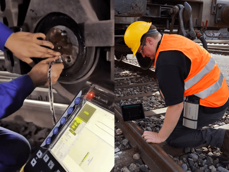
The difference between UT and PAUT is how the beam is made. Conventional ultrasonic testing (UT) uses one element at one fixed angle, such as 45°, 60° or 70°. Phased array ultrasonic testing (PAUT) fires many elements with timed delays, so one probe sweeps a range of angles, typically 40° to 70° on welds, and records an image.
Both methods use the same physics, and neither one decides whether a weld passes. Acceptance comes from the construction code, such as AWS D1.1, ASME Section VIII or ASME B31.3.
This guide compares the two methods, sets out the code basis, works a sectorial scan coverage example on a 1 in. weld, and explains where PAUT fits on rail welds. For how phased array instruments and probes work in depth, see our phased array ultrasonic testing guide.
How is a PAUT beam different from a conventional UT beam?
A conventional UT probe makes one beam at one angle; a phased array probe builds many beams from many small elements. That single difference drives the contrasts in coverage, speed, records and cost.
A conventional angle-beam probe has one crystal on a plastic wedge, and the wedge angle sets the refracted angle in steel. To change from 45° to 70°, the technician changes the wedge or the probe.
The screen shows an A-scan: amplitude against time. The technician raster-scans the weld and builds the picture mentally. Our angle beam testing guide covers that technique and its geometry.
A phased array probe has a row of small elements, often 16, 32 or 64, each pulsed at a slightly different time. The wavefronts add up into one beam whose angle and focal depth are set by the delays. Evident's phased array tutorial explains the delay calculation and beam forming.
The instrument repeats this many times a second, sweeping a fan of angles from one position and drawing a cross-section image. PAUT is still pulse-echo UT: a technique within the UT method, not a separate method.
Key takeaway: PAUT changes how the beam is aimed and how the data is shown; it doesn't change the physics of what reflects sound.
UT vs PAUT: how do they compare feature by feature?
PAUT wins on coverage per pass, imaging and recorded data; conventional UT wins on simplicity, setup time and cost on small jobs. The table sets out the practical differences for weld inspection.
| Feature | Conventional UT | PAUT |
|---|---|---|
| Probe | One element (or a dual-element pair) | Array of many elements, commonly 16 to 64 |
| Beam steering | Fixed by the wedge; change wedges to change angle | Electronic; angle changed by element delays |
| Focusing | Natural focus only, set by crystal size and frequency | Electronic focus at a chosen depth or sound path |
| Scan types | Manual raster, swivel and along-weld scans | Sectorial (S-scan), linear (E-scan), plus manual or encoded line scans |
| Angles per pass | One | A range, for example 40° to 70° in 1° steps |
| Display | A-scan | A-scan plus S-scan, B-scan and C-scan views |
| Coverage | Built up by repeated passes at each angle | A fan of angles from each index position; still needs a scan plan |
| Records | Usually a written report; signals not stored unless an encoded system is used | Encoded data files can store every A-scan for later review and audit |
| Setup time | Short: calibrate one probe and angle | Longer: focal laws, scan plan, encoder and calibration of each beam |
| Equipment cost | Lower | Higher: multi-channel instrument, array probes, wedges, encoder, software |
| Skill needed | UT Level II for the method | UT Level II plus PAUT-specific training and experience |
| Best fit | Short welds, spot checks, thickness readings, simple joints | Long seams, thick sections, recorded inspection, RT replacement programs |
The cost row is qualitative on purpose: prices vary by vendor and channel count, and no neutral published comparison was found. A contractor's day rate also depends on setup, analysis and reporting time.
Conventional UT can also be mechanized and encoded, so the table compares the common case of hand-held UT against encoded PAUT. For that distinction, see AUT vs PAUT.
Key takeaway: the bigger the weld and the more you need a stored record, the stronger the case for PAUT.
What are sectorial scans, linear scans and focal laws?
A focal law is one set of element delays that makes one beam; a sectorial scan sweeps angles from one aperture, and a linear scan steps one angle along the array. These three terms appear in every PAUT procedure.
Focal laws
A focal law tells the instrument which elements to fire, with what delays, giving one beam at one angle and focus. An S-scan from 40° to 70° in 1° steps uses 31 focal laws, each with its own A-scan.
Sectorial scans (S-scans)
An S-scan keeps the same elements active and changes the delays to sweep the angle, giving a fan-shaped cross-section. It is the usual choice for welds, because one position looks at many angles, including the one that meets a fusion face square on.
Linear scans (E-scans)
A linear scan fires a small group of elements, then shifts the group along the array at the same angle. It is the electronic version of a one-angle raster scan. ASTM E2700 names S-scan and E-scan as the two basic modes.
Encoded line scans
For an encoded scan, the probe runs along the weld at a fixed offset with a position encoder, and data is stored by position for later replay and audit. A manual, unencoded PAUT scan is closer to conventional UT with a better display.
Key takeaway: in PAUT, the focal laws and the scan plan are part of the procedure, so they must be written down and checked, not improvised.
Worked example: does one sectorial scan cover a 1 in. weld?
No. In this example, one S-scan position from one side leaves gaps; two index offsets, or scanning from both sides, gives full geometric coverage. This is why codes require a written scan plan.
Inputs
- Plate thickness t = 1.00 in.
- Single-V butt weld, 30° bevel (60° included angle), 1/8 in. root opening
- Examination volume: weld plus 1/4 in. of base metal on each side (an illustrative choice; the procedure and code set the real volume)
- S-scan 40° to 70° shear, 1° steps (31 focal laws)
- Simple ray model: each focal law is one ray from one exit point, with no beam spread and no exit-point shift. Real beams have width, and real wedge exit points move with angle, so check both on a block.
Step 1: weld geometry
At depth z, the fusion face sits 0.0625 + (1.00 − z) × tan 30° from the weld centerline.
- At the root (z = 1.00 in.): 0.0625 in.
- At the cap (z = 0): 0.0625 + 0.577 = 0.640 in., so the cap is 1.28 in. wide.
The probe has to sit off the cap, so the exit point is always more than 0.64 in. from the centerline, plus the wedge front length.
Step 2: leg and skip distances
Sound path per leg = t ÷ cos θ. Full skip on the surface = 2t × tan θ.
| Angle | Sound path, one leg (in.) | Full skip distance (in.) |
|---|---|---|
| 40° | 1.31 | 1.68 |
| 45° | 1.41 | 2.00 |
| 60° | 2.00 | 3.46 |
| 70° | 2.92 | 5.49 |
Step 3: which angle hits a fusion face square on?
The fusion face is 30° from vertical, so a beam at 90° − 30° = 60° meets it at normal incidence, the best angle for lack of sidewall fusion. The 60° beam meets the far-side face in the first leg and the near-side face in the second leg, after the back-wall bounce.
With the exit point a distance X from the centerline, the 60° ray meets each face at depth:
- Far face, first leg: z = (0.640 + X) ÷ (tan 60° + tan 30°) = (0.640 + X) ÷ 2.309
- Near face, second leg: z = (2 × 1.732 + 0.640 − X) ÷ 2.309 = (4.104 − X) ÷ 2.309
| Index offset X (in.) | 60° ray meets far face (first leg) at depth | 60° ray meets near face (second leg) at depth |
|---|---|---|
| 1.00 | 0.71 in. (sound path 1.42 in.) | Past the root (no hit) |
| 1.25 | 0.82 in. (sound path 1.64 in.) | Past the root (no hit) |
| 2.00 | Below the plate (no hit) | 0.91 in. (sound path 2.18 in.) |
| 2.50 | Below the plate (no hit) | 0.69 in. (sound path 2.61 in.) |
| 3.00 | Below the plate (no hit) | 0.48 in. (sound path 3.04 in.) |
Check: every depth is under the 1.00 in. thickness. The second-leg sound path is (2t − z) ÷ cos 60°, so at X = 2.50 it is (2.00 − 0.69) ÷ 0.5 = 2.61 in.
From one position, the 60° ray reaches only a band of one fusion face. Covering both faces squarely from one side needs at least two offsets, for example X = 1.25 in. and X = 2.50 in.
Step 4: total volume coverage
This step checks a 0.02 in. grid across the examination volume, counting any angle from 40° to 70° in the first or second leg.
| Scan plan | Share of the examination volume not reached |
|---|---|
| One side, X = 1.50 in. | About 26% (mostly the upper half of the weld on the probe side) |
| One side, X = 2.50 in. | About 0.4% (small corners) |
| One side, two offsets, X = 1.00 and 2.60 in. | 0% |
| Both sides, X = 1.75 in. each side | 0% |
What the example shows
A 40° to 70° sweep is not automatic full coverage. The index offset, the leg and the scan side all matter, and the fusion faces need the right angle, not just any angle.
ASME Section V and AWS D1.1 both expect a written scan plan that shows coverage. A Level III should check any real plan on a calibration block, because beam spread, exit-point shift and the weld cap change these numbers.
Which codes and standards govern UT and PAUT?
For welds in US practice, the examination method comes from ASME Section V or the welding code's own UT clause, and acceptance comes from the construction code. Most of these documents are paywalled. This summary uses only public pages and agreeing secondary sources, so check clause numbers against the edition in your contract.
| Document | What it covers for PAUT | Status checked |
|---|---|---|
| ASME BPVC Section V, Article 4 | UT examination method for welds, including PAUT, TOFD and FMC appendices | 2025 edition current (ASME) |
| ASTM E2700-26 | Practice for contact UT of welds using phased arrays; S-scan or E-scan; butt and tee welds; 9 to 200 mm | Active, Feb 2026 (ASTM store) |
| ASTM E2491-23 | Guide for evaluating performance of phased-array instruments and systems; sets no performance limits | Active, Aug 2023 (ASTM store) |
| ISO 13588:2019 | Semi- or fully automated phased array testing of fusion welds, 6 mm and up; four testing levels; no acceptance levels | Valid (SIS catalog) |
| ISO 19285:2017 | PAUT acceptance levels for full-penetration ferritic welds, 6 mm and up, linked to ISO 5817 quality levels | Confirmed 2022; revision started |
| AWS D1.1/D1.1M:2025 | Structural steel welding; PAUT annex first added in the 2020 edition | 2025 edition current (AWS) |
ASME Section V, Article 4
Section V says how to examine; acceptance comes from the referencing code, such as Section VIII or B31.3. The 2025 edition is current.
Public summaries place encoded PAUT (E-scan and S-scan linear scanning with linear arrays) in Mandatory Appendix V, TOFD in Appendix III, and full matrix capture in Appendix XI, added in 2019. Manual raster PAUT with linear arrays is commonly cited as Appendix IV; confirm that number in your edition.
An instrument maker's summary of Article 4 and Appendix V gives these working rules:
- an S-scan angle step of no more than 1°, or enough for at least 50% beam overlap
- at least 10% overlap between scan lines
- unprocessed A-scan data recorded, with no thresholding
- a scan increment of no more than 1 mm below 3 in. thickness and 2 mm at 3 in. and above
- indications over 20% of the reference level investigated
Treat these as secondary and check them in the code. ASME also issued code cases for manual phased array S-scan and E-scan work, reported as Code Cases 2557 and 2558.
ASTM E2700 and E2491
ASTM E2700-26 is the general PAUT weld practice. Its scope is angle-beam S-scan or E-scan examination, mainly of butt and tee welds 9 to 200 mm thick. Other thicknesses are allowed where mockups show the technique works. It carries a sizing warning:
"Extreme caution should be used when attempting to size indications using phased array." (ASTM E2700-26, scope 1.2.1)
The practice adds that, without proper procedures, indications can be oversized by beam divergence and by several virtual probes seeing the same reflector.
ASTM E2491-23 is the guide for checking phased array instruments and systems and for spotting drift over time. It sets no pass or fail limits.
ISO 13588 and ISO 19285
ISO 13588:2019 covers semi- or fully automated phased array testing of fusion welds at least 6 mm thick. It targets simple full-penetration joints in low-alloy or fine-grained steel; coarse-grained and austenitic steels also need ISO 22825. It defines four testing levels and no acceptance levels.
ISO 19285:2017 supplies PAUT acceptance levels for indications classified under ISO 13588.
AWS D1.1
AWS D1.1/D1.1M:2025 is the current Structural Welding Code – Steel, though many contracts still cite 2020. D1.1 doesn't require UT on its own; the contract, or AISC 360 and 341 for buildings, decides which welds get UT.
The 2020 edition added a mandatory PAUT annex, reported as Annex H. A vendor summary of the 2020 annex says it applies whenever PAUT is used, covers 3/16 in. to 8 in., and calls for:
- 40° to 70° shear waves
- at least a 16-channel instrument and a 16-element probe at 1 to 6 MHz
- encoded, recorded scans
- its own amplitude tables, with no planar indications allowed
- length measured by the 6 dB drop method
Public summaries of the 2025 edition don't describe changes to the PAUT annex. Confirm the annex letter, tables and personnel rules in the 2025 edition before writing a procedure. Our AWS D1.1 weld inspection criteria article covers the conventional UT rating and visual limits.
Key takeaway: cite the method document and the acceptance document separately in any PAUT procedure or RFP.
Can UT or PAUT replace radiography?
Yes, in many pressure-equipment and piping codes, provided the technique is recorded, demonstrated and accepted to the code's criteria. Recorded PAUT, often combined with TOFD, is the usual way to do it.
ASME Code Case 2235
Code Case 2235 allows UT in lieu of RT for welds in pressure vessels and power boilers. Secondary sources place it under Section I and Section VIII, Divisions 1 and 2, with revision 2235-9 the one most often cited. Its requirements include:
- a defined examination volume
- a written procedure demonstrated on qualification blocks
- qualified personnel
- recorded data with probe position
- flaw acceptance by thickness
The case also sets a minimum material thickness. Check it, and the current revision, for your edition.
ASME B31.3 process piping
B31.3 has its own route. Forum quotations of para. 341.4.1(b)(1) show that random examination of normal fluid service girth welds may be by RT under 344.5 or UT under 344.6.
Code Case 181 gives alternative UT acceptance criteria for welds 25 mm and thicker. The 2016 edition added fracture-mechanics UT acceptance as Appendix R, for techniques that size flaws. Under 344.6.2, a linear indication rejects only if its amplitude and its length both exceed the limits (CONFIRM).
Our UT acceptance criteria standards article sets out those limits, and ASME weld ultrasonic inspection covers the Section V and VIII side.
Bridges
For bridge welds under AWS D1.5, a Florida DOT study compared RT, UT and PAUT on test welds (Wilkinson and Duke, University of South Florida, report BDK84-977-26, 2014). PAUT rejection rates were similar to RT and UT. The authors concluded that "PAUT would make a suitable substitute for RT (and UT) in bridge weld inspection" with an appropriate procedure (ROSA P record).
That is a research finding, not a D1.5 permission.
Key takeaway: UT in lieu of RT is a code-by-code permission with conditions; it isn't automatic because the equipment is phased array.
How are PAUT technicians qualified?
PAUT technicians are certified by their employer, usually under ASNT SNT-TC-1A or ANSI/ASNT CP-189, with PAUT-specific training and experience on top of a UT certification. No outside body certifies them under SNT-TC-1A.
ASNT describes the two documents differently:
- SNT-TC-1A (2024, with addendum) is a recommended practice: "employer guidance" for in-house qualification and certification.
- CP-189 (2024) is a standard that "establishes minimum requirements" for employer-based certification, building on SNT-TC-1A.
Both treat phased array as a technique within the UT method, so the employer's written practice should state the extra PAUT training, experience and practical exam. The PAUT hour tables weren't verified from a public source for this article, so check the current edition (CONFIRM).
Codes add their own rules. A vendor summary of the D1.1:2020 PAUT annex says a UT Level II needs 320 hours of PAUT experience and a practical exam on two flawed samples (CONFIRM in the 2025 edition).
Code cases can add a procedure demonstration. For the base UT levels, see UT Level 2.
Key takeaway: ask for the PAUT-specific line in the technician's certification, not just "UT Level II".
Is PAUT used on rail welds?
PAUT is used on rail welds mainly for verification, sizing, weld-plant work and research; it is not standard revenue-service rail flaw testing in North America. Production rail testing still uses wheel or sled probes at fixed angles.
Rail test vehicles and carts use fixed angles, typically 70° for transverse head defects and 0° for horizontal defects, plus side-looking probes. 49 CFR 213.237 sets how often rail is tested and 213.238 who may operate the equipment; neither names a technology or requires PAUT.
Rail welds are where PAUT gets the most interest, because the weld shape defeats single-angle probes:
- Thermite (aluminothermic) field welds. Test cars miss most of the rail base, so field welds need hand UT of the base (TTCI TD-00-013, 2000). See our aluminothermic weld inspection article.
- Head-contact PAUT trials. A TTCI technology digest described a head-contact phased array prototype, run at up to 20 mph, that found transverse defects under shells and weld and web defects. It could not inspect the base flanges (TTCI TD-16-050, 2016).
- Hand PAUT on suspect welds. A sectorial scan can help size a weld indication found by a test car or hand UT. It needs a written procedure, a reference block in the same rail section and a technician trained on rail geometry.
No FRA rule or published North American rail standard requiring PAUT on in-track rail welds was found. For how PAUT compares with TOFD on rail welds, see PAUT vs TOFD for rail weld inspection.
Key takeaway: for rail, specify conventional UT for compliance testing and keep PAUT for sizing and weld-specific questions.
What can't UT and PAUT do?
Neither method sees every flaw, and PAUT's images can make an inspection look more certain than it is. These limits apply whichever method you pick.
- Surface-breaking flaws. Both UT methods have a near-surface dead zone under the probe. Toe cracks are better found with MT (ferromagnetic steel) or PT.
- Badly oriented flaws. A flaw that lies along the beam reflects little sound back. PAUT's angle range helps but doesn't solve it; a fusion face is best hit near 90° minus the bevel angle.
- Volumetric flaws. Porosity and slag give weak, scattered echoes, and radiography usually characterizes them better. See our weld defect types hub.
- Tight lack of fusion. Very tight lack of fusion can give weak echoes with any NDT method; see lack of fusion in welds.
- Coarse-grained materials. Austenitic welds and cast manganese steel scatter sound, and ISO 13588 points to ISO 22825 for them.
- Sizing. ASTM E2700 warns that PAUT can oversize indications without a proper procedure.
- Surface and curvature. Both methods need couplant and a smooth surface, and PAUT wedges must match pipe curvature within the code's limits.
- Acceptance. No UT image makes a weld acceptable. The construction code does, applied by qualified people.
When should you choose UT, and when PAUT?
Choose conventional UT for short, simple or one-off jobs; choose PAUT for long or thick welds, a stored record, or an RT replacement.
| Situation | Usual choice | Why |
|---|---|---|
| A few short fillet or groove welds, spot checks | Conventional UT | Fast setup; the code's standard rating applies |
| Thickness and corrosion readings | Conventional UT (straight beam) | No need for beam steering |
| Long seams or many identical welds | PAUT, encoded | Coverage per pass and stored data |
| Thick sections, multiple angles needed | PAUT | One probe covers the angle range |
| Owner wants a replayable record or audit trail | PAUT, encoded | Full A-scan data stored by position |
| Replacing RT on a pressure vessel or pipe | PAUT (often with TOFD) to the code case or code rules | Needs a recorded, demonstrated technique |
| Rail flaw compliance testing | Conventional rail UT (test vehicle or cart) | What 213.237 programs use |
| Sizing a suspect rail weld indication | Hand PAUT or conventional UT by a trained technician | Better picture of the weld volume |
Write the choice into the contract: the method document, the acceptance code and edition, scan plan approval, data format and who reviews the data.
How EMA Industries applies this
EMA Industries provides AWS D1.1 structural weld UT, MT and PT, rail weld inspection, ultrasonic rail flaw testing and NDT Level III services from Southern California, and mobilizes nationwide. On a weld or rail weld scope, we help owners decide whether conventional UT meets the code or PAUT is worth the setup. The method, acceptance code and scan plan go into the procedure before work starts.
See our ultrasonic examination services or contact EMA Industries to discuss a scope.
Frequently asked questions
Is PAUT more accurate than conventional UT?
PAUT usually gives better coverage and a clearer picture of where a reflector sits, because it sweeps many angles and draws an image. It is not automatically better at sizing: ASTM E2700 warns it can oversize indications without proper procedures.
Does AWS D1.1 allow PAUT?
AWS D1.1 has included a mandatory PAUT annex since the 2020 edition. Vendor summaries say it covers 3/16 in. to 8 in., uses 40° to 70° shear waves and requires encoded scans with the annex's own acceptance tables. Check the 2025 edition for the exact clause, tables and personnel rules.
Can PAUT replace radiography on a pressure vessel?
PAUT can replace radiography under ASME Code Case 2235 and related code rules when the conditions are met. These include a minimum thickness, a demonstrated written procedure, qualified personnel, recorded data and the code's flaw acceptance criteria.
Why does a PAUT inspection cost more than conventional UT?
PAUT needs a multi-channel instrument, array probes, an encoder and software. It also takes more time for focal laws, the scan plan and data review. On long or thick welds, faster coverage can offset that setup cost.
Do rail test cars use phased array?
Production rail flaw testing in North America uses fixed-angle probes in wheels or sleds, typically 70° and 0° plus side-looking probes. Phased array has been trialed on rail, including a TTCI head-contact prototype in 2016. It is mainly used to verify and size indications at welds.
Sources
- ASME, BPVC Section V: Nondestructive Examination (2025 edition; Article 4 appendix details from secondary summaries)
- ASTM International, E2700-26 Standard Practice for Contact Ultrasonic Testing of Welds Using Phased Arrays
- ASTM International, E2491-23 Standard Guide for Evaluating Performance Characteristics of Phased-Array Ultrasonic Testing Instruments and Systems
- SIS, SS-EN ISO 13588:2019 Non-destructive testing of welds – Ultrasonic testing – Use of automated phased array technology
- ISO, ISO 19285:2017 Phased array ultrasonic testing (PAUT) – Acceptance levels
- American Welding Society, AWS announces release of D1.1/D1.1M:2025
- Sonatest, PAUT of Welds to 2020 AWS D1.1 (vendor summary, 2023)
- Inspenet / Sonatest, PAUT weld inspection according to ASME Section V Article 4 (vendor summary, 2026)
- Evident, Ultrasonic phased array in lieu of radiography and Phased array tutorial
- Becht, ASME B31.3 – Substantive Changes in the 2016 Edition (Frikken, 2016)
- Wilkinson and Duke, Comparative testing of RT, UT and PAUT in accordance with the AWS D1.5 bridge welding code, Florida DOT report BDK84-977-26, 2014
- ASNT, Standards: SNT-TC-1A and ANSI/ASNT CP-189
- TTCI, Technology Digest TD-16-050 (2016) and TD-00-013 (2000)
- 49 CFR 213.237 and 213.238, eCFR Part 213 Subpart F