

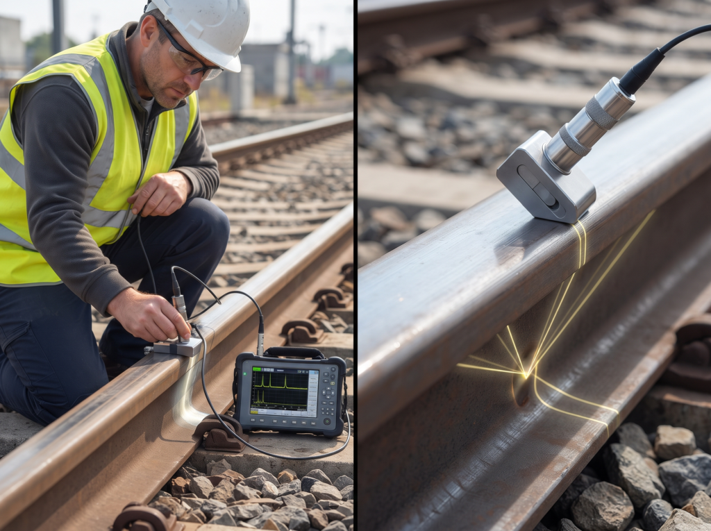
Angle beam testing plays an important role in ultrasonic testing when a straight beam cannot reliably reveal a discontinuity. Angle beam testing directs ultrasonic energy into a component at a controlled angle, helping inspectors examine flaws whose orientation makes direct reflection difficult. This approach has become especially important in weld inspection, where weld geometry and defect orientation often demand examination from the side rather than directly above the weld.
The principle sounds simple, but the physics behind the beam is more involved. Once sound leaves the probe wedge and enters the test material, its direction and wave mode can change. Understanding that transition explains why particular probe angles work so well.
What Is Angle Beam Testing?
Angle beam testing uses an ultrasonic probe and wedge arrangement to introduce sound into a test piece at an angle. The transducer converts electrical energy into mechanical vibration, while the wedge guides that vibration toward the material surface. A couplant removes the air gap between the wedge and the test surface so ultrasonic energy can enter the component efficiently.
In contact inspection, the wedge usually sits directly on the test surface. The wedge may form part of the probe housing or remain a separate, replaceable component.
The main advantage appears when the expected discontinuity does not face a straight-beam probe favorably. Angle beam testing can direct sound toward fusion boundaries, cracks, lack of fusion, and other weld discontinuities.
The next question is what causes the beam to bend and change mode at the material boundary.
Refraction, Mode Conversion and Snell’s Law
When an ultrasonic wave crosses from one material into another, its direction can change. This bending is called refraction. The amount of bending depends mainly on the sound velocities in the two materials and the angle at which the wave reaches the boundary.
Angle beam testing therefore depends heavily on controlled refraction. The wedge and test material have different acoustic properties, so the beam changes direction at their interface.
Snell’s Law describes this relationship:
[ = ]
Here, θ1 represents the incident angle, θ2 represents the refracted angle, V1 represents the sound velocity in the first material, and V2 represents the velocity in the second material. The equation helps relate the wedge angle to the desired beam angle inside the test piece.
Mode conversion adds another important part of the process. A longitudinal wave entering the boundary at an appropriate angle can generate both longitudinal and shear components in the second material. The two modes travel at different velocities, so they also refract at different angles.
A shear wave moves particle motion perpendicular to the direction of propagation. A longitudinal wave moves particle motion parallel to propagation. In conventional weld inspection, the refracted shear wave weld inspection usually becomes the principal inspection beam because its direction and characteristics suit many common weld examinations.
The first critical angle helps explain why. As the incident angle increases, the refracted longitudinal-wave angle can reach 90 degrees. Beyond that condition, a propagating longitudinal solution is no longer possible in the test material. The shear-wave component remains available, allowing the probe arrangement to produce predominantly shear-wave inspection at commonly used angles.
This is why an angle-beam probe is more than a transducer mounted at a slant. Its wedge, material properties, incident angle, and wave velocities work together to create a controlled beam inside the component.
Common Refraction Angles in Ultrasonic Testing
Several refracted shear-wave angles appear frequently in conventional ultrasonic inspection. The most familiar are 45°, 60°, and 70°. These numbers normally describe the beam angle inside the test material, measured from the normal to the surface.
| Beam angle | Typical characteristic | Potential inspection use |
| 45° | Relatively shallow beam | Selected component geometries and coverage requirements |
| 60° | Versatile intermediate angle | Common weld-volume examination |
| 70° | Steeper beam | Selected flaw orientations and weld regions |
The correct choice depends on material thickness, weld profile, access, expected flaw orientation, and the inspection procedure. A higher angle is not automatically better. The objective is to place the sound beam where it can interrogate the relevant volume and interact favorably with likely reflectors.
This balance makes angle selection a practical decision rather than a fixed rule for every ultrasonic inspection application.
How the Sound Beam Travels Through a Weld
During a weld examination, the probe usually sits on one side of the weld and sends the refracted beam through the base material toward the weld. The sound travels along its first leg until it reaches the opposite surface. The bottom surface reflects the beam, sending it back upward along a related path.
That reflected portion forms a second leg. By moving the probe across the examination area, the inspector changes the beam’s point of entry and sweeps sound through different portions of the weld. Repeated movement allows the beam to cover the weld body, fusion lines, root region, and other areas that might contain discontinuities.
Angle beam testing becomes particularly useful here because a weld is not a simple flat reflector. Its crown, root, fusion boundaries, and internal geometry can all generate echoes. The inspector must recognize these expected responses before deciding whether another indication represents a discontinuity.
Once the beam encounters a real discontinuity, the returned signal can change in amplitude and position. That response is where interpretation begins.
Detecting and Interpreting Discontinuities
A discontinuity can reflect ultrasonic energy back toward the probe when its orientation and location provide a suitable reflecting surface. Common weld-related indications include cracking, lack of fusion, lack of penetration, and porosity. The resulting echo may appear as a distinct indication within the expected weld zone.
Inspectors do not normally identify a defect from amplitude alone. They consider the sound path, probe position, indication movement, weld geometry, and relationship between the indication and known reference points. An echo that moves predictably with a geometric feature may come from the weld profile rather than a flaw.
Cracks and lack-of-fusion indications can produce strong responses because they often present relatively planar reflecting surfaces. Porosity can behave differently because it contains smaller, irregular reflectors. The indication’s appearance and movement therefore provide useful clues during evaluation.
Calibration shear wave and written inspection procedures establish the conditions under which these signals should be interpreted. Without proper setup, even a clear echo can lead to an incorrect conclusion.
What Is the First Critical Angle in Ultrasonic Testing?
Yes, the first critical angle is the incident angle at which the refracted longitudinal wave reaches 90 degrees along the material boundary. At that point, the longitudinal component no longer propagates into the test material as a normal transmitted wave. The shear component can continue to propagate at an angle, which supports conventional shear-wave angle-beam inspection.
Angle Beam Testing Probe Selection and Equipment
A typical angle-beam system includes a piezoelectric transducer, wedge, housing, cable, instrument, and coupling medium. The transducer generates and receives ultrasonic signals, while the wedge controls how those signals enter the test material.
Three parameters strongly influence probe selection: frequency, refracted angle, and element size.
1. Frequency affects the balance between resolution and penetration. Higher frequencies generally improve the ability to distinguish small reflectors but can experience greater attenuation. Lower frequencies generally penetrate farther, particularly in coarse-grained or highly attenuative materials, but provide lower resolution.
2. Beam angle determines how the sound crosses the component and interacts with anticipated discontinuities.
3. Element size affects the beam characteristics, coverage, and probe footprint.
Inspectors also consider component thickness, material structure, surface condition, access, and the applicable inspection standard. A probe that performs well on a thin, fine-grained plate may not provide the same performance on a thick or coarse-grained component.
Applications of Angle Beam Testing
Weld inspection remains one of the most important uses of angle beam testing. Pipes, structural welds, plates, fabricated components, and other welded products can contain discontinuities whose orientation makes straight-beam examination less effective.
In welds, the technique can help locate and evaluate cracks, lack of fusion, lack of penetration, and other discontinuities. The beam can travel through the weld from different directions, allowing inspection of areas near fusion lines and within the weld body.
Angle beam testing methods also have applications beyond welds. Plates, tubes, bars, forgings, and selected composite components can require angled ultrasonic inspection when expected discontinuities have an unfavorable orientation for a normal beam.
The inspection can only produce meaningful results when the beam characteristics and instrument response have been verified.
Calibration and Factors Affecting Inspection Accuracy
Before an inspection begins, the system requires appropriate calibration. The process can verify the probe’s exit point, refracted angle, sound path, and sensitivity. Reference or calibration blocks provide known features against which the system response can be checked.
Couplant also plays an important role because air severely restricts ultrasonic transmission between the probe and test surface. A suitable coupling layer allows sound to pass efficiently while maintaining consistent probe movement.
Surface condition can influence coupling and probe contact. Rough, dirty, curved, or damaged surfaces can affect the beam and the repeatability of indications. Probe wear can also alter the expected response over time.
Straight Beam Testing vs Angle Beam Testing
| Feature | Straight Beam Testing | Angle Beam Testing |
| Beam direction | Approximately perpendicular | Angled |
| Common wave | Longitudinal | Usually shear |
| Typical target | Laminar or parallel flaws | Angular and weld-related flaws |
| Wedge | Usually unnecessary | Commonly required |
| Main principle | Direct propagation | Refraction and mode conversion |
Neither method universally replaces the other. Straight-beam UT remains valuable for many laminar discontinuities and thickness measurements, while angle beam testing provides an important solution for welds and other situations involving unfavorable flaw orientations.
Final Thoughts
Angle beam testing provides a controlled way to direct ultrasonic energy toward discontinuities that may escape a straight-beam examination. Refraction and Snell’s Law determine how the beam enters the material, while mode conversion makes refracted shear waves practical for many weld inspections. Common 45°, 60°, and 70° configurations offer different coverage and interaction with potential reflectors.
Reliable results also depend on correct frequency, probe selection, calibration, coupling, scanning, and interpretation. When these factors match the component geometry and expected discontinuity orientation, angle beam testing becomes considerably more effective.
Key Takeaways
- Angle beam testing inspection redirects sound toward flaws that straight beams can miss.
- Refraction changes the ultrasonic beam direction when sound crosses material boundaries.
- Snell’s Law helps determine the refracted angle from known sound velocities.
- Mode conversion allows angled probes to generate useful shear waves inside materials.
- Forty-five, sixty, and seventy degrees represent common refracted inspection angles.
- Weld geometry and flaw orientation strongly influence appropriate angle selection decisions.
- Probe frequency affects penetration, resolution, and sensitivity during ultrasonic examinations.
- Proper calibration establishes reliable beam angle, sound path, and inspection sensitivity.
- Echoes from weld geometry must be distinguished from genuine discontinuity indications carefully.
- Effective inspection depends on matching probe characteristics with component and flaw conditions.
Frequently Asked Questions
What is an angle beam?
Yes, an angle beam is an ultrasonic beam that travels through a test material at an angle relative to its surface. A wedge commonly creates the required refracted direction. In conventional weld inspection, the beam is often a refracted shear wave. The selected angle helps the sound interact favorably with discontinuities that a perpendicular beam may not detect effectively.
What is a 60 degree beam angle?
Yes, 60° is a common refracted angle used in ultrasonic testing, particularly for weld inspection. The angle normally describes the direction of the beam inside the test material, measured from the normal to the surface. A 60° beam provides a useful balance between sound-path coverage and access to different portions of a weld.
How to calculate beam path in ultrasonic testing?
Yes, beam path can be calculated using sound velocity and travel time, together with the beam geometry. For a basic sound path, distance equals velocity multiplied by travel time, with appropriate consideration of instrument timing. Beam angle then helps determine horizontal and vertical components. In practical inspection, calibrated equipment and known reference blocks verify calculated sound-path values.
How to determine beam angle?
Yes, beam angle can be determined from the probe specification, wedge design, material velocities, or direct calibration. Snell’s Law relates the incident and refracted angles through their respective sound velocities. In practical ultrasonic inspection, a suitable calibration block can verify the actual refracted angle and probe exit point before examination of the production component.
What is the symbol for beam angle in degrees?
Yes, the standard symbol for degrees is °. Ultrasonic beam angles are therefore commonly written as 45°, 60°, or 70°. In conventional angle beam testing, the stated angle generally describes the refracted beam direction inside the test material relative to the normal. Clear angle notation helps inspectors distinguish beam orientation from the physical angle of a wedge.
