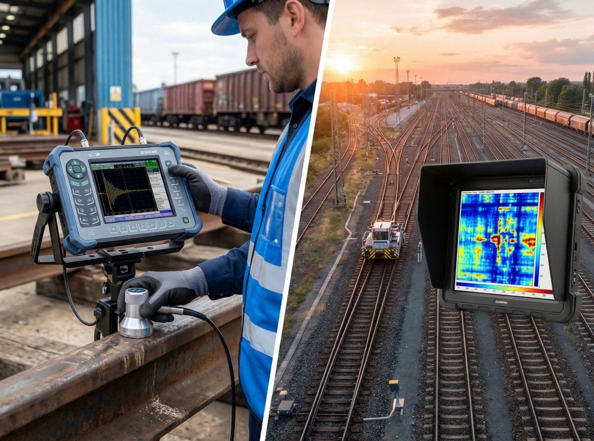
Ultrasonic rail testing data interpretation means reading the B-scan-style channel displays that a test car or cart records, then confirming each suspect on an A-scan. Under 49 CFR 213.237(j)(4), a search only counts when a qualified operator interprets the equipment responses, so these reading rules decide whether a defect is found.
Rail testing doesn't use the textbook trio equally. Test cars and carts show channel strips along the rail, the A-scan verifies a suspect at the stop, and C-scan appears mostly in phased array (PAUT) research. This guide shows what typical features and defects look like on the strip, with a worked 70° location example.
Contents: Scan types · Reading a B-scan · Normal rail · Joints and bolt holes · Welds · Loss of bottom · 70° transverse defects · Horizontal split heads · Shelling and noise · False calls · Pattern table · A-scan verification · C-scan · Limits · FAQ
What do A-scan, B-scan and C-scan show in rail testing?
The three displays differ in what they plot against what. An A-scan plots echo amplitude against time at one probe position. A B-scan plots echo time (depth or sound path) against probe position along the rail. A C-scan is a plan view of amplitude or depth over an area, which needs raster or array scanning.
| Display | Axes | Where it appears in rail testing | What it is good for |
|---|---|---|---|
| A-scan | Amplitude vs time at one position | Hand verification at a stop; also stored per channel by digital systems | Sound path, depth and amplitude of one suspect; sizing by hand technique |
| B-scan (strip or channel display) | Time or depth vs distance along the rail, one lane per channel | Main display on test cars and walking carts | Seeing patterns along the rail: bolt holes, welds, base echo, lost signal, defect echoes |
| C-scan | Plan view of amplitude or depth over an area | Not a standard test-car display; used in encoded PAUT, lab and research work | Mapping a reflector's extent over a scanned area |
An AAR technology digest says a detector car's reflected sound energy "is displayed on a time chart", and a trained operator learns to tell defects from bolt holes and welds (TTCI TD-16-030, 2016). Vendors draw that chart differently, so check your system's legend.
Key takeaway: in rail testing the B-scan strip finds the suspect, and the A-scan confirms it.
How is ultrasonic rail testing data interpretation done on a B-scan?
Read the strip channel by channel against what the rail should look like at that spot. The horizontal axis is encoder distance along the rail. Each lane is one probe channel, and the vertical position in a lane is echo time, which scales to sound path.
A typical channel set is 70° forward and reverse for transverse defects in the head, 0° for horizontal defects and the base echo, 37–45° for the web and bolt holes, and often side-looking channels. No public source names one standard North American channel set, so treat this as typical. Why each angle suits a given crack plane is covered in the science behind ultrasonic testing.
Five reading rules replace the generic advice in many UT guides:
- A continuous horizontal band is usually normal. In the 0° lane the base echo runs as a steady band at full rail height. A second, shallower 0° band is a horizontal reflector such as a split head, and the base band usually weakens under it.
- Angled beams draw a slope for almost any reflector. As the probe approaches and passes a reflector the sound path shortens, then lengthens. Bolt holes, rail ends and weld geometry all draw slopes, so a slope alone doesn't mean a crack.
- Forward and reverse channels mirror each other. A real head reflector usually shows in both 70° directions, offset along the strip. An echo in one direction only needs a reason before it is dismissed.
- Known features repeat; defects break the pattern. Bolt holes come at the drilling spacing and welds have their own signature. An extra line, a missing echo or an unexpected feature is the suspect.
- Missing signal matters as much as extra signal. A gap in the base echo can be a defect, a coupling loss or surface damage, and it isn't a clean result until it is explained.
Key takeaway: interpret each echo against the expected rail geometry at that location, never by its shape alone.
What does sound rail look like on the B-scan?
Sound rail shows a steady base echo in the 0° lane and little else. Away from joints and welds, the angled channels should be quiet inside their gates, and the 0° base echo should hold its amplitude.
The times below show where the 0° echoes fall on 136RE rail, using a longitudinal velocity of 0.2320 in./µs (5,890 m/s) with the wedge or wheel delay excluded. The head depth of 1-15/16 in. comes from one supplier drawing and should be confirmed against the rail section in use.
| 0° reflector (136RE, 7-5/16 in. rail) | Depth below running surface | Round-trip time |
|---|---|---|
| Horizontal split head at 0.50 in. | 0.50 in. | 4.31 µs |
| Horizontal reflector at 1.00 in. | 1.00 in. | 8.62 µs |
| Underside of the head | 1.94 in. | 16.70 µs |
| Top of a bolt hole | 3.59 in. | 30.98 µs |
| Base (bottom of rail) | 7.31 in. | 63.04 µs |
An echo at 31 µs between bolt holes is not a bolt hole, and one at 4.3 µs over a long stretch is a horizontal reflector in the head. With the common 5,920 m/s gauge default the base echo moves to about 62.7 µs, which is why velocity is calibrated on rail.
How do bolt holes, joints and rail ends appear?
Bolt holes draw a repeating set of echoes at the joint, and the rail end draws a strong echo across the angled channels. In the 0° lane the base echo drops out over each hole and a hole echo appears at mid-web depth. In the 37–45° lanes each hole draws a short slope; a research PAUT B-scan showed "the four bolt holes" of a joint "as diagonal lines" (TTCI TD-16-050, 2016).
On that scan the bolt hole crack appeared "as an additional line on the second bolt hole". So compare each hole with its neighbors and with the holes across the gap: a branch, an extra slope or one odd hole is the suspect for a bolt hole crack.
At the rail end the angled channels pick up the end face as a strong reflector, every lane loses signal across the gap, and the pattern repeats in mirror image on the next rail. The rail end is also a datum for measuring a suspect's position. The joint can't be skipped as noisy: 49 CFR 213.237(f) requires equipment that detects defects between joint bars.
Key takeaway: at a joint, compare every hole with its neighbors; the crack is the line that doesn't repeat.
How do thermite and flash-butt welds appear?
Field thermite welds usually show geometry echoes from the collar, and flash-butt welds usually show little or nothing. A thermite weld's cast collar and its ground or unground head profile reflect angled beams, so the 37–45° and 70° lanes often show a symmetrical cluster of echoes centered on the weld. The 0° base echo may dip at the collar. A flash-butt weld's upset is trimmed, so its signature is usually small.
The weld signature drives weld false calls. In a 2000 TTCI survey of thermite welds removed from track, 24.4 percent of the 41 detector car finds examined contained no observable defect. TTCI suggested that "the various surface finishes introduced from thermite welds" can reflect 45° and 70° shear waves the way slag, gas pockets and cracks do (TTCI TD-00-013, 2000).
PAUT research shows the same issue. TTCI noted that "un-ground flashing surrounding the weld" causes reflections that must be told apart from defects, and showed a healthy electric flash-butt weld giving a lower head fillet echo on only one probe angle (TD-16-050). A later study warned that thermite welds' "variable geometry" generates indications that could be misread as defects (TTCI TD21-027, 2021).
At a weld, the suspects are an echo inside the weld volume rather than at the collar edges, an echo on one side only, and a weld that looks different from others of its type on the same run. A defective weld under 49 CFR 213.113 has discontinuities exceeding 5 percent of the head area individually or 10 percent in aggregate, so disposition needs a hand-verified size. See aluminothermic weld inspection and flash-butt weld inspection.
What does loss of bottom mean on a rail B-scan?
Loss of bottom is a gap in the 0° base echo: sound sent down from the running surface didn't come back from the base. It is a symptom, not a defect type. The cause can be a horizontal defect in the head, a vertical split head or piped rail deflecting the beam, a bolt hole, surface damage such as shelling or engine burns, or a plain coupling loss.
The 2006 New Brighton, Pennsylvania derailment shows why. The last test before the accident showed "an intermittent loss of bottom signal" over about 9 feet, and the initiating defect lay "within a 2-inch area that had a loss of bottom signal" (NTSB RAR-08/02). The railroad's instruction then required a rerun only for 0° loss of bottom of 5 feet or more, and the testing contractor said shelling would have interfered with the base signal.
FRA's track division staff director told the NTSB that a search allowing that much loss of bottom would not be a continuous search as FRA defines it. That ties loss of bottom to the valid-search rule:
"Valid search means a continuous inspection for internal rail defects where the equipment performs as intended and equipment responses are interpreted by a qualified operator as defined in § 213.238." — 49 CFR 213.237(j)(4)
A loss of bottom that can't be explained by a known feature should be rerun or hand tested. If the rail still can't be searched, it is untested rail. 49 CFR 213.241(c)(6) requires the record to show the location of any track not tested under 213.237(g), and 213.237(h) gives the options: retest, run at 25 mph or less, or replace the rail.
Key takeaway: a lost base echo is untested rail until it is explained, and it is not a false call.
How do transverse defects appear in the 70° channels?
A transverse defect in the head usually shows as a short echo inside the head gate of both 70° channels, offset along the strip in opposite directions. A transverse fissure is a crosswise fracture at substantially a right angle to the rail length, so it faces a 70° beam at about 20° off normal. A 0° beam meets it edge-on, which is why the head is searched with 70° channels.
A detail fracture starts at or near the head surface, often at the gauge corner under shelling, so its echo sits shallower and is more easily masked. Gauge-side and field-side 70° channels help place a defect across the head; disposition follows the 213.113 table by hand-verified type and size.
Worked example: from 70° sound path to position along the rail
A forward-looking 70° shear channel shows a head indication. The analyst reads its peak on the A-scan and locates it from a thermite weld seen on the same strip.
Inputs: shear velocity 0.1280 in./µs (3,250 m/s); refracted angle 70°; peak round-trip time 37.5 µs, with the wheel delay already zeroed out; at the peak, the probe index point is 31.0 in. past the weld centerline, measured on the encoder.
| Step | Calculation | Result |
|---|---|---|
| Sound path | 0.1280 × 37.5 ÷ 2 | 2.40 in. |
| Depth below running surface | 2.40 × cos 70° (0.3420) | 0.821 in. |
| Surface distance ahead of the index point | 2.40 × sin 70° (0.9397) | 2.255 in. |
| Depth check against the head | 0.821 ÷ 1.9375 in. (136RE head, CONFIRM) | 42% of head depth, so inside the head |
| Reflector position | 31.0 + 2.255 | 33.26 in. past the weld |
| Where the reverse 70° channel peaks | 33.26 + 2.255 | 35.51 in. past the weld |
| Offset between the two channel peaks | 35.51 − 31.0 | 4.51 in. |
The midpoint of the two peaks, (31.0 + 35.51) ÷ 2 = 33.26 in., matches the reflector position. Where a display plots echoes at the probe position, one defect's forward and reverse indications sit about 4.5 in. apart on the strip.
Each 1 µs of timing error moves the sound path 0.064 in. (0.022 in. of depth, 0.060 in. of position). An angle error matters more for depth: at 68° the same path gives 0.899 in. and at 72° gives 0.742 in., while position moves less than 0.03 in.
The datum makes the number usable. FRA research on rail head repair welds needed defects located within ±1 inch, and measuring from a nearby bolt hole, rail end or weld gave about ±0.5 inch, while GPS defined location only "to the nearest few feet" (FRA RR 20-16, 2020).
How does a horizontal split head appear in the 0° channel?
A horizontal split head shows as an early 0° echo in the head, with the base echo weakened or lost beneath it. Under 49 CFR 213.113 it is "a horizontal progressive defect originating inside of the rail head, usually 1/4 inch or more below the running surface". It is face-on to the 0° beam, so the echo is strong.
On the B-scan this reads as a 0° band at head depth, about 4.3 µs for a split 0.50 in. down on 136RE, with the base echo dropping beneath it. Its length estimates the defect's length, but the disposition size comes from hand scanning, and the crew can look for the flat spot. A split that turns up or down becomes a compound fissure and also shows in the angled channels; see horizontal split head.
A vertical split head is parallel to the 0° beam, so its 0° response is indirect (loss of bottom), and side-looking channels give the direct echo.
Why do shelling and surface noise matter?
Shelling and other surface damage scatter the sound at the running surface, so the strip shows noise near the top of the head gate and intermittent loss of bottom, while the defects below can go unseen. This is masking. It mainly affects detail fractures, which start at or near the surface, often under shells.
The best-known measured figure comes from a 1998 TTCI benchmark of six hi-rail test systems on known defects: transverse defects under shells were found about 62 percent of the time against about 77 percent with no apparent surface anomaly (TTCI TD-99-006). The sample was small, 7 defects under shells against 33 without, so treat it as an indication, not a rate. FRA's 2014 rail integrity rule also listed shells, engine burns, spalling, flaking, corrugation and head checking as the main poor surface conditions behind rail flaw detection limits (79 FR 4234).
On the strip, shelling shows as a ragged echo field at the top of the 70° head gate, short gaps in the 0° base echo, and weld or bolt-hole signatures that fade where they must be present. Noise is not a reason to clear rail: heavy shelling may need a hand test, a slower rerun or grinding before a valid search. See rail shelling and spalling.
Which patterns cause false calls?
False calls come mostly from normal geometry that looks like a defect: weld collars and flashing, bolt holes, rail ends and worn profiles. TTCI's phased array work put it simply:
"Not all indications are from defects, e.g., bolt holes and some welds have distinct ultrasonic signatures that must be distinguished from defects and from bolt holes and welds with defects." — TTCI TD-16-030, 2016
The digest adds that on worn rail "the wrong volume of material is inspected", and that agreement between probes "reduces the likelihood of false alarm". An FRA handheld rail UT study found that calibration varied between operators and that too low a threshold gives too many false positives (FRA DOT/FRA/ORD-26/07, 2026).
Three rules keep the terms straight:
- A suspect is not yet a defect. Under 49 CFR 213.240(e)(4), for owners running continuous testing, "A suspect location is not considered a defect under § 213.113(c) until it has been field-verified by a person qualified under § 213.238."
- Lost coupling is not a false call. Rail that couldn't be searched is untested rail under 213.241(c)(6), not a benign indication.
- No federal false-call rate exists. The 213.240(g) annual report counts tests, defects and service failures, not benign suspects.
A full treatment of causes and costs is in false calls in rail UT.
Rail UT indication patterns at a glance
The table below gives typical appearances for common rail features and defects. Displays and channel sets differ by system, so treat it as a starting point for a written procedure, to be reviewed by the owner's or contractor's NDT Level III.
| Feature or defect | Main channel(s) | Typical appearance on the strip | What to do |
|---|---|---|---|
| Sound rail | 0° | Steady base echo at full height; angled lanes quiet in their gates | Use the base echo as the coupling and continuity check |
| Bolt holes | 0°, 37–45° | Base echo drops at each hole; hole echo at mid-web; short slopes at the drilling spacing | Compare each hole with its neighbors; an extra or branching line is a suspect bolt hole crack |
| Rail end and joint gap | All | Strong end-face echo in angled lanes, all lanes lose signal across the gap, mirrored on the next rail | Use as a datum; confirm the joint was searched between the bars (213.237(f)) |
| Thermite weld | 37–45°, 70°, 0° | Symmetric collar echoes about the weld; 0° may dip at the collar | Compare with other welds of the same type; hand verify echoes inside the weld volume or on one side only |
| Flash-butt weld | Angled | Little or no signature; sometimes a small geometry echo on one angle | An isolated single-angle echo is often geometry, but verify per procedure |
| Loss of bottom | 0° | Gap in the base echo, continuous or intermittent | Explain it by a known feature or rerun and hand test; if still unsearched, record as untested rail |
| Transverse defect or detail fracture | 70° forward and reverse | Short echo in the head gate in both directions, offset along the strip | Stop, hand verify with 70°, size, and apply the 213.113 table |
| Horizontal split head | 0° | Early echo at head depth with base echo lost beneath it | Hand scan to size the length; look for a flat spot on the running surface |
| Vertical split head or piped rail | 0° (indirect), side-looking | Loss of bottom over a length; direct echo only on side-looking channels | Verify with side-looking or hand techniques; don't expect a 0° flaw echo |
| Shelling and surface noise | 70°, 0° | Ragged near-surface echoes; intermittent loss of bottom | Treat as possible masking; hand test, rerun slower, or grind before calling the rail searched |
Where does the A-scan fit?
The A-scan is the verification tool: once the strip flags a suspect, the operator stops, hand tests and reads the echo on an A-scan. The A-scan gives the sound path, depth and amplitude of that one reflector, and hand scanning gives its size. It doesn't show the defect's shape.
Reading the screen itself is covered in how to read a flaw detector. For rail work, carry the strip's numbers to the stop: channel, time, side of the head and distance from the nearest datum.
Under 213.240, continuous-test data is reviewed by a qualified interpreter and every suspect is field-verified by a person qualified under 213.238; in stop-and-verify testing one operator usually does both. Either way, the A-scan at the stop is where a suspect becomes a typed, sized defect or is cleared with a reason.
Where is C-scan used in rail?
C-scan is not the standard test-car display. A plan-view image needs encoded raster scanning or an array that covers an area, which conventional fixed-angle wheel probes moving along the rail don't do. Rail test cars present strip or B-scan-style channel maps and A-scans.
Area images appear mainly in phased array research. TTCI's head-contact PAUT prototype produced rolling B-scans and, in FRA RR 20-16, "heat map" images with 256 amplitude colors to locate head defects for repair welds; it can't inspect the base flanges (TD-16-050). TTCI's thermite weld study modeled PAUT probe sets for a portable weld scanner (TD21-027), and lab scans of rail and weld samples can map a reflector's extent. C-scan is not used to monitor long track sections. See phased array ultrasonic testing.
What rail UT data interpretation can't do
Interpretation can only work with what the beam reached. These are the main limits:
- Most of the base flanges are outside the test. Head-contact probes cover the head, web and the base under the web.
- Masking hides defects under surface damage, and fixed angles miss cracks tilted away from the beam or shifted by a worn profile.
- Closed cracks reflect less than open ones, because a compressed crack transmits some sound.
- The strip doesn't size defects. Size for 213.113 comes from hand verification.
- Standards don't supply acceptance. EN 13674-1 is a rail product specification (profiles and grades), not an acceptance standard, and EN 16729-1 sets in-track UT principles without saying what to do with results. US disposition comes from 49 CFR 213.113 and owner procedures; AREMA publishes recommended practice, not federal rules.
TTCI put conventional UT at "about 90 percent" of flaws found, leaving about 10 percent undetected during periodic inspection (TD-16-030), a general figure, not one for any run.
How EMA Industries applies this
EMA Industries performs ultrasonic rail flaw testing for transit agencies, short lines and industrial track owners, and provides NDT Level III services. We're based in Southern California and mobilize nationwide. A useful test report should show each suspect's channel, position from a named datum, verification result and size, plus every stretch where loss of bottom or surface damage prevented a valid search. To discuss a testing program, see our ultrasonic rail testing services or contact us.
Related reading: How ultrasonic testing works for railways · 49 CFR 213.237 rail flaw detection requirements · Continuous vs stop-and-verify rail testing
Frequently asked questions
What is the difference between an A-scan and a B-scan in rail testing?
An A-scan shows echo amplitude against time at one probe position and is used to verify a suspect at the stop. A B-scan plots echo time against distance along the rail for each channel, and it is the main display a test car or cart records.
How do you read a B-scan from a rail test car?
Read each channel against the expected rail geometry at that location. A steady 0° base echo is normal, bolt holes and welds repeat a known signature, and a suspect is an echo that breaks the pattern or a gap in the base echo that no feature explains.
Why does the base echo disappear on a rail B-scan?
Loss of bottom means the 0° sound didn't return from the base. It can come from a horizontal defect, a vertical split head, a bolt hole, surface damage such as shelling, or lost coupling. Until it is explained it is treated as untested rail.
Is C-scan used in rail flaw detection?
Not as a routine test-car output. C-scan needs area or array scanning, so it appears mainly in phased array research, weld research and lab work on rail samples.
What is a false call in rail ultrasonic testing?
A false call is a suspect that field verification shows to be sound rail, often caused by weld collars, flashing, bolt holes or worn profiles. Rail that couldn't be searched because of lost coupling is a different thing: it is untested rail.
Sources
- 49 CFR 213.237, Inspection of rail, eCFR (text checked on Cornell LII, 24 Oct 2026)
- 49 CFR 213.240, Continuous rail testing, eCFR
- 49 CFR 213.241, Inspection records, eCFR
- 49 CFR 213.113, Defective rails, eCFR
- Track Safety Standards; Improving Rail Integrity, 79 FR 4234 (January 24, 2014), Federal Register
- NTSB RAR-08/02, Derailment of Norfolk Southern train 68QB119, New Brighton, Pennsylvania (2008)
- FRA RR 20-16, Locating and Sizing Rail Head Defects for Rail Head Repair Welds Using Phased Array Ultrasonics (September 2020)
- FRA DOT/FRA/ORD-26/07, model-assisted POD for handheld rail UT (July 2026)
- TTCI TD-16-030, High-Speed Rail Flaw Detection Using Phased Array Ultrasonics (July 2016)
- TTCI TD-16-050, phased array rail inspection prototype results (November 2016)
- TTCI TD-00-013, Thermite Weld Failure Survey (July 2000)
- TTCI TD21-027, Phased Array Ultrasonic Beam Modeling for Rail Thermite Welds (September 2021)
- TTCI TD-99-006, Benchmarking Results of North American Rail-Flaw Detection Technologies (February 1999)
- EN 13674-1:2011+A1:2017, Railway applications – Track – Rail – Part 1 (catalog listing)
- EN 16729-1:2016, Non-destructive testing on rails in track – Part 1: ultrasonic inspection (catalog listing)