
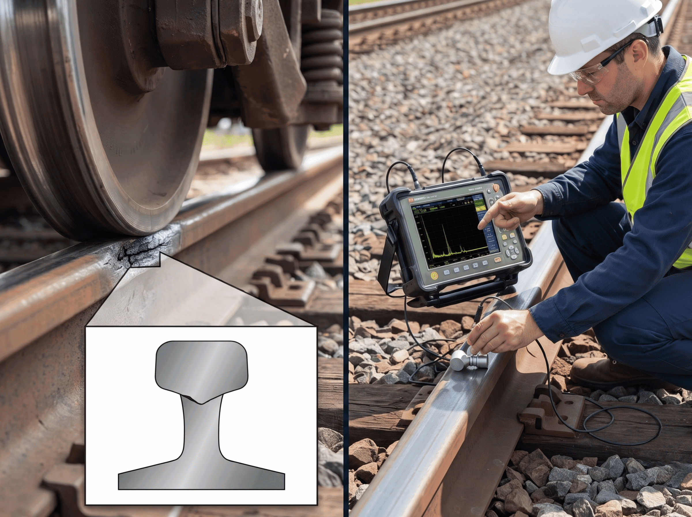
Transverse Fissure in Rail represents one of the most critical safety challenges facing modern railway systems. This progressive crosswise fracture develops within the rail head, creating extraordinary risks for train derailments and passenger safety. Understanding this defect becomes essential for anyone involved in railway maintenance, safety management, or infrastructure assessment.
The numbers are stark. Between 2005 and 2014, transverse cracks caused 21.7% of all railway accidents in the United States. Consider this: in 1911, the Philadelphia Day Express derailment occurred due to a transverse fissure. Twenty-nine people died. Sixty more were injured. That single tragedy fundamentally changed how the industry approaches rail inspection and defect detection.
What Defines This Critical Defect?
Transverse Fissure in Rail is officially a progressive crosswise fracture originating from a crystalline center or nucleus deep within the rail head. It spreads outward as a smooth, bright, or dark round or oval surface developing substantially at a right angle to the rail's length. The distinguishing features? The crystalline center point. The nearly smooth surface surrounding the development area.
The defect typically appears centrally located within the railhead. Unlike other fracture types originating at the surface or edges. When examined under magnification, Transverse Fissure in Rail exhibits distinctive "growth rings." Similar to tree cross-sections. Evidence of how the fracture develops over time through repeated stress cycles.
Multiple instances can exist simultaneously within a single rail section. Creating compound danger scenarios. This is why detection matters so critically.
These defects are inherent to manufacturing. They appear predominantly in noncontrol cooled rail produced before the mid-1930s. But here's the concerning part: modern high-chrome rail can also develop these fractures. Hydrogen imperfections create the same vulnerability. This defect isn't a problem of the past. It remains an ongoing concern despite steel production advances.
The Root Causes: Where It All Starts
Oxide Inclusions and Stress Risers
Oxide inclusions represent the leading cause of Transverse Fissure in Rail formation. During steel manufacturing, impurities present in the ingot become elongated through forging operations. These oxide particles act as stress risers, points where mechanical stress concentrates and magnifies exponentially.
When a stress riser exists within the rail head, constant flexing under wheel loads promotes crack growth from this nucleation point. The inclusion flaw expands. Eventually the rail fractures. Grain sizes from 1.0 to 5.0 micrometers prove particularly problematic. Higher particle densities significantly increase failure probability.
Manufacturing's Hidden Problems
The manufacturing environment creates multiple pathways for defect development:
- Rapid solidification affects inclusion distribution
- Slag entrapment during casting creates discontinuities
- Porosity introduces weakness points
- Incomplete fusion during welding leaves vulnerable zones
Lead oxide-based inclusions. Manganese sulfide-based inclusions. Entrapped particulates. All function as potential nucleation sites. The ratio of long-side to short-side dimensions directly influences stress concentration and fracture likelihood.
Service-Induced Stress and Fatigue
Installation doesn't end the problem. It begins it. Rails experience relentless mechanical loading that activates latent defects. Growth accelerates through constant cyclic flexing from passing train wheels. Work hardening of the railhead material compounds the issue. Wheel-rail contact creates residual stress zones. Engine slip damage occurs where driving wheels spin on rail.
And here's what's particularly dangerous: wheel slip generates localized heating. This creates additional stress concentration. Dormant defect zones suddenly expand. The fracture propagates faster than most inspection schedules can detect.
What Gets Found During Testing?
Rail testing identifies numerous defect categories. Yet Transverse Fissure in Rail consistently emerges as the most dangerous. The Federal Railroad Administration classifies 14 distinct rail defect types under 49 CFR 213.113. Bolt hole cracks to vertical split heads. Among these, Transverse Fissure in Rail ranks as the most critical. It initiates internally. Remaining invisible until the fracture reaches catastrophic size.
Defects discovered during testing fall into three location categories. Rail head defects. Web defects. Base defects. Transverse Fissure in Rail predominantly occurs in the railhead. That's the surface carrying wheel loads. That's where rail integrity is determined.
Detection proves challenging because external signs remain minimal. Internal growth reaches advanced stages before any surface indication appears. Modern detection systems that identify subsurface defects represent critical safety investments. Not optional upgrades. Essential infrastructure protections.
How Detection Actually Works
Visual and Contact Inspection
The earliest method? Visual inspection. Completely inadequate for internal defects. Modern contact-based ultrasonic transducers roll along the rail, transmitting sound waves through the rail structure. Reflected signals indicate defects. But here's the problem: horizontal cracks and shelling mask the ultrasonic signature of internal fractures. Creating false negatives. Additionally, contact transducers limit inspection speeds to approximately 50 kilometers per hour.
What is Ultrasonic Testing for Flaw Detection?
Advanced ultrasonic detection systems represent a significant evolution. They employ several distinct approaches. Conventional pulse-echo configuration uses piezoelectric transducers. Guided wave systems propagate elastic waves through rail structure in sophisticated patterns. Laser-generated ultrasound creates non-contact excitation. Rotational laser vibrometry measures deformation without physical contact.
Laser-generated ultrasound systems produce focused laser pulses on the rail head. Exciting elastic waves that travel through rail material. Reflected echoes return to laser vibrometry sensors measuring angular velocity and angular displacement with remarkable precision. These non-contact methods enable inspection speeds exceeding conventional contact-based approaches.
The principle underlying detection relies on acoustic impedance differences between steel and air. Sound waves encountering a crack partially reflect at the discontinuity. Creating an echo indicating defect presence, location, and estimated size. Modern systems incorporate automated pattern recognition algorithms analyzing signal characteristics to distinguish fractures from other defects and debris.
Eddy current methods operate at low frequencies (70-100 Hertz) specifically chosen to penetrate deeply into the rail head. This approach proves particularly valuable for detecting defects beneath horizontal cracks that would mask ultrasonic detection. Horizontal cracks make subsurface transverse cracks essentially transparent to eddy current probes. That's why this dual-method approach works.
Which Probe is Used to Detect Transverse Defects in Rail Head?
Multiple probe types serve different detection methodologies. Conventional ultrasonic transducers function as piezoelectric probes. Converting electrical energy into mechanical vibrations. These contact-based probes generate and receive sound waves, typically operating at frequencies between 500 kilohertz and 5 megahertz.
Linear array probes arrange multiple elements in a line. Enabling sophisticated beam steering. Phased array transducers offer enhanced flexibility by allowing electronic beam manipulation without physical probe movement.
Eddy current probes generate electromagnetic fields detecting defects through material conductivity changes. These non-contact probes excel at detecting fractures beneath surface conditions. Surface proximity doesn't significantly affect performance. Making them suitable for corroded or rough rail surfaces common in field conditions.
Laser-based probes represent emerging technology. Generating ultrasonic waves through laser irradiation without mechanical contact. Laser vibrometry sensors detect resulting vibrations through laser reflection measurement. Offering non-contact capability ideal for high-speed inspection applications.
The Challenges Nobody Talks About
Despite technological advances, detection before catastrophic failure remains challenging. The masking problem is genuinely insidious. Horizontal cracks, shelling, and head checks create reflective surfaces. They prevent ultrasonic waves from reaching deeper defects. This limitation directly caused the Superior, Wisconsin train derailment in 1991. A hazardous material spill forced nearby town evacuation. People had to leave their homes because of what couldn't be detected underground.
Early detection difficulty arises because defect signatures remain small. Internal growth reaches substantial proportions before producing significant acoustic reflections. The crystalline nucleus of a nascent defect produces minimal acoustic reflections. Disappearing within background noise. Engineers must set detection thresholds carefully. Too sensitive? False positives reduce inspection efficiency. Too insensitive? Developing defects get missed.
The speed versus accuracy trade-off creates operational constraints. Non-contact ultrasonic systems enable higher inspection velocities than contact methods. But sensitivity may decrease with increased speed. Track owners must balance thoroughness against operational efficiency. Advanced signal processing and artificial intelligence now enable faster detection without sacrificing accuracy. Representing major advancement in railway safety technology.
Safety and Economics
During 2002 to 2011, transverse defects caused 1,181 derailments. That's $294 million in direct damage costs. The 1990s witnessed particularly severe impacts. One decade alone recorded $162 million in damage. But monetary costs miss the point. This defect poses immeasurable risks to human life. Emergency response capabilities. Environmental safety when hazardous materials are involved.
The historical significance cannot be overstated. Railway evolution itself was driven partly by addressing this defect. American railroads experienced extensive transverse fractures beginning in the late 1800s and early 1900s. This prompted development of systematic inspection methods. Preventive maintenance protocols. Standards that persist today.
Modern economic modeling demonstrates something crucial: proactive detection and repair prevents far greater losses than inspection program costs. A single major derailment exceeds $50 million in recovery expenses. That doesn't account for fatalities, injuries, or environmental restoration. One accident. Fifty million dollars. Suddenly inspection budgets look like excellent investments.
Regulatory Requirements and What They Mean
The Federal Railroad Administration requires verification within four hours of detection. Remedial actions follow the Remedial Action Table. This prescribes specific timelines based on defect severity and rail location. Three options exist for non-compliant tracks. Repair the defect. Reduce operating speeds to a lower track class. Remove the track from service entirely.
Track Geometry Measurement Systems (TGMS) and Automated Trigonometric Geometry Measurement Systems (ATGMS) provide modern monitoring capabilities. They detect numerous defect types simultaneously. These systems have evolved considerably since the 1970s. Detection technologies now achieve high sensitivity to identifying geometry conditions. And subsurface defects. They're not just measuring anymore. They're actively protecting lives.
Current FRA Requirements and Compliance
The Federal Railroad Administration requires track owners to verify indications of Transverse Fissure in Rail within four hours of detection. Remedial actions must follow the Remedial Action Table, which prescribes specific timelines based on defect severity and rail location. Three options exist for non-compliant track: repair the defect, reduce operating speeds to a lower track class, or remove the track from service entirely.
Track Geometry Measurement Systems (TGMS) and Automated Trigonometric Geometry Measurement Systems (ATGMS) provide modern monitoring capabilities that detect numerous defect types simultaneously. These systems have evolved considerably since the 1970s, with detection technologies now achieving high sensitivity to identifying geometry conditions and subsurface defects including Transverse Fissure in Rail.
Final Thoughts
This defect represents a persistent challenge demanding sustained industry attention and technological innovation. It originates from manufacturing impurities. It evolves through decades of cyclic loading. Creating unpredictable failure points. Threatening track integrity. Endangering passenger safety.
The evolution from visual inspection to advanced laser-based ultrasonic systems demonstrates genuine commitment to addressing this critical issue. Future detection technologies promise even greater sensitivity. Enabling identification before critical growth occurs.
Meanwhile? Continued vigilance through established inspection protocols remains essential. Railway professionals must maintain a comprehensive understanding of these defect characteristics. Modern infrastructure demands nothing less.
Key Takeaways
- Transverse Fissure in Rail causes 21.7% of United States railway derailments according to Federal Railroad Administration data from 2005-2014.
- Oxide inclusions create stress risers in rail steel, initiating defect development through decades of accumulated cyclic wheel loading during operations.
- Manufacturing process defects including slag entrapment and incomplete fusion directly contribute to defect formation in newly produced railway rail steel.
- Service-induced factors such as wheel slip and contact fatigue accelerate existing defect growth rates in operational railway track infrastructure conditions.
- Internal crystalline nucleation distinguishes this defect from surface-initiated defects, making subsurface detection extraordinarily challenging for conventional inspection methodologies.
- Horizontal cracks effectively mask ultrasonic detection signals in contact-based inspection systems, creating false negatives during routine railway track assessments.
- Non-contact ultrasonic and laser-based detection methods overcome masking limitations, enabling significantly higher inspection speeds than conventional contact-based systems.
- Federal Railroad Administration regulations require verification and remedial action within strict timelines based on defect severity and railway location factors.
- Economic analysis demonstrates proactive detection and repair costs substantially less than consequences of single catastrophic derailment events in railways.
- Modern artificial intelligence and automated pattern recognition technologies enable rapid, accurate defect identification without sacrificing inspection velocity or detection sensitivity.
FAQs
What is a rail test?
Rail tests use ultrasonic, eddy current, and visual methods identifying defects and Transverse Fissure in Rail precisely. Safety absolutely depends.
What is ultrasonic testing for flaw detection?
Ultrasonic testing employs high-frequency sound waves to detect rail defects including Transverse Fissure
Which probe is used to detect transverse defects in rail head?
But multiple probe types serve different purposes. Piezoelectric, phased array, eddy current, laser-based. Each addresses specific detection needs within railways.
What are the types of defects in rails?
The Federal Railroad Administration classifies fourteen rail defect types, with Transverse Fissure in Rail critical. Shelling, detail fractures, breaks occur.
How to detect cracks in railway track?
And multiple detection methods apply systematically. Visual inspection. Ultrasonic and eddy current techniques. Laser systems. Track Geometry Systems. All work.