A compound fissure in rail is a progressive fracture that starts as a horizontal split head and then turns up or down across the rail head, as defined in 49 CFR 213.113(d). On Class 1 to 5 track, a compound fissure covering 5% to under 70% of the head area takes remedial action B (30 mph maximum), 70% to under 100% takes A2, and 100% takes A.
Because the defect has a horizontal part and a transverse part, finding it takes two ultrasonic beams: a 0° straight beam for the horizontal separation and a 70° angle beam for the transverse turn. It is also one of the four defect types that count toward the FRA rail service failure rate under 49 CFR 213.237.
This guide covers the regulatory definition, how the defect differs from a transverse fissure and a horizontal split head, how ultrasonic testing finds and sizes it, the exact 213.113 remedial actions with worked examples, the T220 accident cause code, and what testing can't tell you.
What is a compound fissure in rail?
A compound fissure is a horizontal split head that has turned transverse. The FRA Track Safety Standards define it in 49 CFR 213.113(d):
"Compound fissure means a progressive fracture originating from a horizontal split head that turns up or down, or in both directions, in the head of the rail. Transverse development normally progresses substantially at a right angle to the length of the rail." — 49 CFR 213.113(d), eCFR
Three points in that definition matter in the field:
- The origin is a horizontal split head. A compound fissure is not "several intersecting cracks", a description some drafts use. It is one defect that began as a horizontal separation inside the head.
- It can turn up, down or both ways. The transverse part may grow toward the running surface, toward the web, or in both directions from the horizontal plane.
- The transverse part ends up roughly perpendicular to the rail. Once that happens, the defect behaves like a crosswise fracture and can break the rail across its section.
The Subpart G version of the definition, for Class 6 and higher track in 49 CFR 213.337, adds a useful note for failure analysis: compound fissures "require examination of both faces of the fracture to locate the horizontal split head from which they originate." When a broken rail is examined after a service failure, the horizontal origin is often on only one side of the break.
Key takeaway: if the horizontal origin isn't there, the defect isn't a compound fissure.
How is a compound fissure different from a transverse fissure or a horizontal split head?
A compound fissure has the origin of a horizontal split head and the failure plane of a transverse fissure. The three defects are often confused on a test readout, but 213.113(d) separates them by where they start and which way they grow.
| Feature | Compound fissure | Transverse fissure | Horizontal split head |
|---|---|---|---|
| Where it starts | A horizontal split head inside the head | A crystalline center or nucleus inside the head | Inside the head, usually 1/4 in. or more below the running surface |
| Direction of growth | Horizontal first, then up, down or both, ending roughly at a right angle to the rail | Outward from the nucleus as a round or oval surface at a right angle to the rail | Horizontally in all directions |
| Surface sign | Often none until late; may share the flat spot of the original split head | Usually none until the rail breaks | Generally a flat spot on the running surface; a lengthwise crack at the side of the head when it breaks out |
| How 213.113 sizes it | Percent of head cross-section area | Percent of head cross-section area | Length in inches |
| Remedial action (Class 1–5) | B, A2 or A | C, D, A2 or [E and H], A or [E and H] | H and F, I and G, B, or A if broken out |
| Main UT beam | 0° for the horizontal part, 70° for the transverse part | 70° | 0° |
| Counts toward the 213.237 service failure rate | Yes | Yes | No |
Sources: 49 CFR 213.113(c) and (d); 49 CFR 213.237(j). The beam column describes typical practice and should be confirmed against your test system's procedure.
The difference matters for disposition, not just labeling. A horizontal split head is sized by length, and a 3 in. split head takes actions I and G (30 mph, reinspect in 30 days). Once the same defect turns transverse, it is sized by head area, and anything from 5% upward takes at least remedial action B. A rail that was being reinspected on a 30-day cycle may now need a speed restriction at once.
For the full definitions of each defect, see EMA Industries' articles on the transverse fissure in rail and the horizontal split head. A detail fracture is different again: 213.113(d) says it starts "at or near the surface of the rail head" and "should not be confused with transverse fissures, compound fissures, or other defects which have internal origins."
Key takeaway: a compound fissure is a horizontal split head that has graduated to a transverse defect, and its remedial action changes with it.
What causes a compound fissure to form?
A compound fissure forms when an existing horizontal split head grows under traffic and its edge turns into the transverse plane. The regulation defines the defect by its geometry, not its cause, so the causes below are the ones commonly described in rail metallurgy and track practice.
The starting horizontal split head. Horizontal split heads usually begin at an internal discontinuity in the head, such as a seam, segregation or a non-metallic inclusion lying parallel to the running surface. Repeated wheel loads open and extend that discontinuity horizontally. Treat this as a general description; the cause of any one defect can only be confirmed by examining the broken faces.
The turn. As the horizontal separation grows, the stress at its edge changes. Bending of the head under each wheel, lateral flange loads on curves and longitudinal stress all act on the crack front. At some point the crack front stops following the horizontal plane and turns up or down. Several conditions are generally associated with this:
- heavy axle loads and impact loads from flat wheels, battered joints or poor support
- lateral loading on curves
- longitudinal tensile stress in continuous welded rail in cold weather, when rail temperature drops below the rail neutral temperature
- residual stress in the rail head from manufacture or head hardening
What we don't know: growth rate. The original version of this article said a compound fissure grows slowly "until 30 to 35 percent of head area." We found no FRA, AREMA or peer-reviewed source for that figure, so it has been removed. The 2014 Improving Rail Integrity rule did cite detail fracture growth of more than 5% of head area per million gross tons when it lowered the threshold for detail fractures and transverse fissures, but that figure applies to detail fractures, not compound fissures. Growth depends on traffic, rail section, temperature and the defect itself. The regulation responds by treating any compound fissure of 5% or more as needing a speed restriction straight away.
Rail age. Control cooling of rail was introduced around the late 1930s to prevent hydrogen shatter cracks, which were a known nucleus of transverse fissures. Older rail is often described as more prone to internal-origin defects in general. We found no source that ties compound fissures specifically to pre-control-cooled rail, so don't assume newer rail is immune.
Key takeaway: every compound fissure began as a horizontal split head, so finding and removing split heads early is the main way to prevent them.
How does ultrasonic testing find a compound fissure in rail?
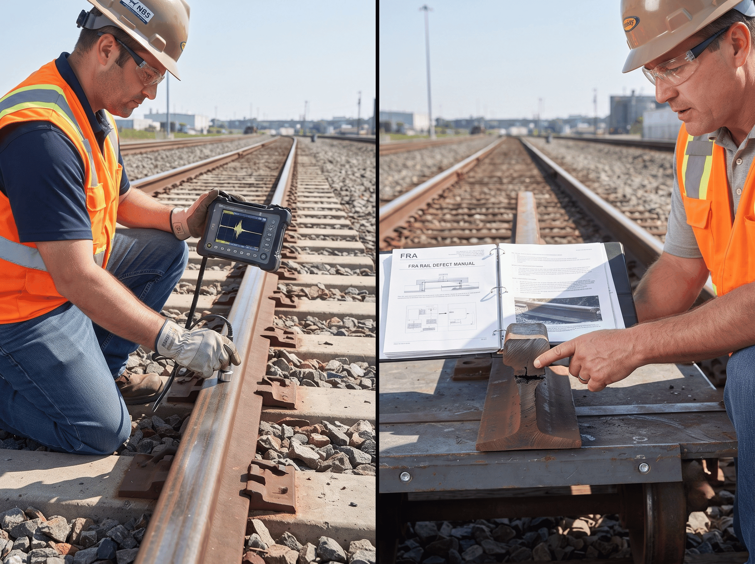
Ultrasonic rail testing finds a compound fissure by combining two beams: a 0° straight beam detects the horizontal part and a 70° shear-wave angle beam detects the transverse part. Neither beam alone gives the full picture.
The physics follows from the orientation of each part of the defect. An ultrasonic beam reflects best from a surface it hits at or near a right angle. A flaw lying parallel to the running surface reflects a 0° beam straight back, but it deflects an angle beam away from the probe. A flaw lying across the rail does the opposite.
| Part of the defect | Orientation | Beam that finds it | What the operator typically sees |
|---|---|---|---|
| Horizontal split head (origin) | Parallel to the running surface | 0° straight beam (longitudinal wave) | An echo from inside the head, earlier than the normal base echo, and usually a loss or drop of the base (back-wall) echo |
| Transverse turn | Roughly at a right angle to the rail | 70° shear-wave angle beam, looking forward and backward | A head-area reflector from the 70° channels at the same location as the 0° indication |
| Both together | Horizontal plus transverse | 0° and 70° channels at one spot | The pattern that should make the operator suspect a compound fissure rather than a plain split head |
The table reflects typical rail test configurations. A common search unit pairs a 0° transducer for split heads and head-and-web separations with 70° transducers aimed at the gauge, center and field side of the head for transverse defects. Some systems add 37° to 45° probes for bolt holes and the web. The exact channels and gates depend on the equipment, so confirm them against the operating procedure.
Search units on a hi-rail vehicle or a walking cart scan continuously. Every indication then needs a hand test to confirm and classify it. Under 49 CFR 213.113(b), an indication of a defect that needs remedial action A, A2 or B, which covers every compound fissure of 5% or more, must be verified immediately, not within the normal four hours. The equipment operator must be qualified under 49 CFR 213.238.
For background on how the beams and search units work, see how ultrasonic testing works for railways.
Worked example: classifying an indication on a hand test
A test car flags a location on the field side of a curve. Its 0° channel showed a head-area echo over about 4 in. of rail, with the base echo dropping out. Its 70° forward channel also showed a reflector at the same location. Here's how the hand test might run:
- Mark the location and confirm the rail section and any visible surface condition, such as shelling, a flat spot or a dark streak on the running surface.
- 0° scan: map the horizontal separation along the rail and across the head. Its depth below the running surface and its length are recorded. A length of about 4 in., with nothing else, would size it as a horizontal split head over 2 in. but not over 4 in. (actions I and G).
- 70° scan, forward and backward: look for a reflector rising from or dropping from the end of the horizontal separation. A confirmed transverse component at the edge of the split head means the defect is a compound fissure.
- Estimate the transverse size as a percentage of the head cross-section area, using the system's sizing procedure. Suppose the operator estimates 40%.
- Classify and act: a compound fissure of 40% falls in the 5% to under 70% band, so remedial action B applies at once: a speed no higher than 30 mph, set by a designated person (see the next section).
Note what changed between step 2 and step 5. Sized as a split head alone, the rail could have run at 30 mph with a 30-day reinspection. Classified as a compound fissure, the same rail needs immediate verification and a designated person's speed decision. Misclassifying the defect as a plain split head would leave the transverse part unmanaged.
Key takeaway: a 0° indication with a 70° indication at the same spot is the signature to investigate as a compound fissure.
What does 49 CFR 213.113 require when a compound fissure is found?
On Class 1 to 5 track, 49 CFR 213.113 requires a person designated under 213.7 to decide whether the track can stay in use, and if it can, the rail must be replaced or repaired or the remedial action in the table must start before trains run over it. Paragraph (a) puts it this way:
"If the designated person determines that the track may continue in use, operation over the defective rail is not permitted until— (1) The rail is replaced or repaired; or (2) The remedial action prescribed in the table contained in paragraph (c) of this section is initiated." — 49 CFR 213.113(a), eCFR
The compound fissure row of the 213.113(c) remedial action table:
| Percent of rail head cross-sectional area weakened by the defect | Remedial action (if the rail is not replaced) |
|---|---|
| Less than 5% | No action in the table |
| 5% to less than 70% | B |
| 70% to less than 100% | A2 |
| 100% | A |
What each action means:
| Note | Requirement |
|---|---|
| A | A designated person visually supervises each operation over the defective rail |
| A2 | A designated person visually inspects the rail and may then allow operation without visual supervision at no more than 10 mph for up to 24 hours before another visual inspection, or replacement or repair |
| B | Speed over the defective rail limited to what a designated person authorizes, with at least one year of supervisory experience in railroad track maintenance; never over 30 mph or the maximum for the track class, whichever is lower |
Sources: 49 CFR 213.113(c), eCFR; the table is printed as an image online, so check it in the annual CFR edition on govinfo or the 2014 Federal Register rule.
Notice what the compound fissure row does not offer. For a transverse fissure or detail fracture, the table allows joint bars (actions C, D and E) at the smaller sizes. For a compound fissure, there is no joint-bar option at any size; the only choices are a speed restriction, supervised operation, or replacing the rail.
Worked example: the same size, two different defects
Two defects of similar size are found on a Class 4 line with a 60 mph freight speed:
| Defect | Size | Remedial action | What it means in practice |
|---|---|---|---|
| Transverse fissure | 40% of head area | D | Joint bars applied within 7 days; 30 mph maximum until they're applied |
| Compound fissure | 40% of head area | B | 30 mph maximum (or lower, as the designated person decides) until the rail is replaced; no joint-bar option |
| Compound fissure | 75% of head area | A2 | Visual inspection by a designated person, then 10 mph for up to 24 hours at a time |
| Compound fissure | Through the full head | A | Every train is visually supervised over the rail until it is replaced or repaired |
In most cases, a track owner who finds a compound fissure of any reportable size plans to replace the rail rather than run under B for long, because B carries no end date and holds the speed at 30 mph or below.
Key takeaway: the compound fissure thresholds are 5%, 70% and 100%, and the remedies are B, A2 and A, with no joint-bar option.
Why is 213.337 the wrong rule for Class 1 to 5 track?
49 CFR 213.337 covers defective rails on Class 6 and higher track only; on Class 1 to 5 track the rule is 213.113. The original version of this article cited 213.337 as the governing rule without mentioning 213.113, and that was an error for almost every reader of this page.
| Track | Defective rail rule | Internal rail inspection rule | Designated person |
|---|---|---|---|
| Class 1 to 5 (up to 80 mph freight, 90 mph passenger) | 49 CFR 213.113 | 49 CFR 213.237 | Under 213.7 |
| Class 6 to 9 (Subpart G, high-speed) | 49 CFR 213.337 | 49 CFR 213.339 | Under 213.305 |
Transit agencies, short lines and industrial track owners, who are EMA Industries' main clients, almost never operate Class 6 track. Any procedure, RFP or report that cites 213.337 for their track should be corrected to 213.113.
How is a compound fissure recorded and coded?
A compound fissure found by testing is recorded under 49 CFR 213.241; a rail that breaks from one counts as a service failure under 213.237 and, in an FRA-reportable accident, is coded T220. These are three separate systems, and they're often mixed up.
| What happens | Rule or system | What's required |
|---|---|---|
| Found by an internal rail test | 49 CFR 213.241 | Record the date, track and limits, defect location, type and size (if not removed before the next train), the initial remedial action and its date. Keep records 2 years after the inspection and 1 year after the remedial action |
| Rail breaks in service | 49 CFR 213.237(a) and (j) | A broken rail from a transverse fissure, compound fissure, detail fracture or vertical split head is a service failure and counts toward the segment's failure rate (0.08 to 0.10 per mile per year, depending on traffic) |
| Rail breaks and causes a reportable accident | FRA accident report, Form F6180.54, Appendix C cause codes | Cause code T220, "Broken Rail - Transverse/compound fissure" |
Two things follow from this. First, T220 covers transverse and compound fissures together, so FRA accident statistics can't tell you how many accidents came from compound fissures alone. Second, 213.113 itself has no numeric defect codes; it names defects and lettered remedial actions. Numbers like "TF 101" or "CF 309" are not FRA codes. EMA Industries' article on FRA defect codes explains the difference between the T-series cause codes and the 213.113 defect names. For test intervals, valid searches and the failure rate, see 49 CFR 213.237 rail flaw detection requirements.
The original article said FRA and the AAR both inspect track. The AAR is an industry association; it publishes standards and recommended practices but does not inspect or enforce. Track safety is enforced by FRA and, on rail transit, by the state safety oversight agency.
What can't rail flaw testing tell you about a compound fissure?
Ultrasonic testing can miss or undersize a compound fissure when the horizontal part shadows the transverse part, when the rail surface blocks the beam, or when the split lies outside the beam path. These limits should be stated in any test report.
- Shadowing by the horizontal split. A horizontal separation reflects the sound above it, so a transverse defect below it can be hidden from beams entering from the running surface. A 2020 US patent on rail head testing (US 10,766,510) describes "detecting detailed transverse fractures that are in the shadow or masked by the horizontal defects" as an unsolved problem. A downward-turning compound fissure is exactly this case.
- Surface condition. Shelling, head checks, spalling and heavy wear scatter the beam and break the probe's coupling with the rail, which can mask internal defects. See rail shelling and spalling.
- Position across the head. A 0° beam from the running surface covers the part of the head above the web best. A horizontal split near the gauge or field corner may give a weaker 0° response, and the 70° channels must be aimed to cover those areas.
- Sizing is an estimate. The percentage of head area is estimated from the echo response and scan extent, not measured. A defect near a band edge (close to 70%, for example) should be treated as the larger size.
- No growth prediction. A test tells you the defect's size on the test date. It doesn't tell you how fast it will grow, which is why 213.113 imposes the remedial action immediately.
- Not a visual inspection substitute, and the reverse. A compound fissure is usually invisible until late. A flat spot, a dark streak on the running surface or a rust-stained crack under the head may appear, but by then the defect is often large.
Key takeaway: a clean test isn't proof of a sound rail where the surface is badly shelled or a split head is present.
How can track owners reduce compound fissure risk?
The most effective control is to find horizontal split heads early and replace the rail before they turn transverse. Practical steps include:
- Keep to the 213.237 test interval or better. On Class 4 and 5 track and on Class 3 track with passenger trains or hazmat traffic, that means no more than 370 days or 30 MGT between tests, whichever is shorter.
- Plan to replace split heads, not just reinspect them. A horizontal split head on a 90-day or 30-day reinspection cycle is the precursor of a compound fissure.
- Ask for both beams in the report. Ask the test provider to record 0° and 70° findings at each defect location, so a split head with a transverse component is not reported as a plain split head.
- Grind to keep the surface testable. Preventive grinding controls rolling contact fatigue and shelling, which keeps the running surface clean enough for the probes to couple.
- Manage CWR stress. Keeping the rail neutral temperature in range under the CWR plan (49 CFR 213.119) limits tensile stress in cold weather, when transverse defects are most likely to break.
- Track the service failure rate per segment. Every rail broken by a compound fissure counts toward the 213.237 rate, so a cluster on one segment is a reason to test more often.
How EMA Industries applies this
EMA Industries provides ultrasonic rail flaw testing for transit agencies, short lines and industrial track owners from Southern California, mobilizing nationwide. On compound fissure calls, the deliverable should give the 0° and 70° findings at each location, the defect type as defined in 213.113(d), the estimated head-area percentage and the remedial action band, so the owner's designated person can act without reinterpreting the data. EMA Industries also offers NDT Level III services to review rail test procedures and sizing practice. To scope a test program, contact EMA Industries.
Frequently asked questions
What is the difference between a compound fissure and a transverse fissure?
A transverse fissure starts from a crystalline center or nucleus inside the head and grows outward at a right angle to the rail. A compound fissure starts as a horizontal split head and then turns up or down into the transverse plane. Under 213.113 they also have different remedial actions: a transverse fissure allows joint bars at smaller sizes, while a compound fissure goes straight to B, A2 or A.
What remedial action does FRA require for a compound fissure?
On Class 1 to 5 track, 49 CFR 213.113 requires remedial action B for a compound fissure of 5% to under 70% of the head area, A2 for 70% to under 100%, and A for 100%. B limits speed to 30 mph or less, as set by a designated person. The owner can always replace or repair the rail instead.
How do you detect a compound fissure with ultrasonic testing?
Use a 0° straight beam to find the horizontal separation and a 70° angle beam to find the transverse part. A 0° indication and a 70° indication at the same location point to a compound fissure. The indication is then confirmed by a hand test, and for a defect needing action A, A2 or B, it must be verified immediately under 213.113(b).
What FRA cause code is used for a compound fissure?
In FRA accident reporting, a rail broken by a compound fissure is coded T220, "Broken Rail - Transverse/compound fissure." The code is shared with transverse fissures. 49 CFR 213.113 itself uses defect names and lettered remedial actions, not numeric codes.
Does a compound fissure count as a rail service failure?
Yes. Under 49 CFR 213.237, a broken rail caused by a transverse fissure, compound fissure, detail fracture or vertical split head is a service failure, and it counts toward the segment's annual failure rate.
Sources
- 49 CFR 213.113, Defective rails, eCFR (definition in (d); remedial action table in (c)), current as of October 2026
- Cornell LII text of 49 CFR 213.113 (alternate copy)
- 49 CFR Part 213, 2024 annual edition, govinfo (full text, including the 213.113 and 213.337 definitions and remedial action notes)
- 49 CFR 213.237, Inspection of rail, eCFR
- 49 CFR 213.238, Qualified operator, eCFR
- 49 CFR 213.241, Inspection records, eCFR
- 49 CFR 213.337, Defective rails (Class 6 and higher), eCFR
- 49 CFR 213.339, Inspection of rail in service (Class 6 and higher), eCFR
- Track Safety Standards; Improving Rail Integrity (January 24, 2014), Federal Register
- FRA Appendix C, Train accident cause codes: Track, roadbed and structure (numeric), FRA Office of Safety Analysis
- US Patent 10,766,510, Method and apparatus for detecting defects located in the head area of rail (granted September 8, 2020)