

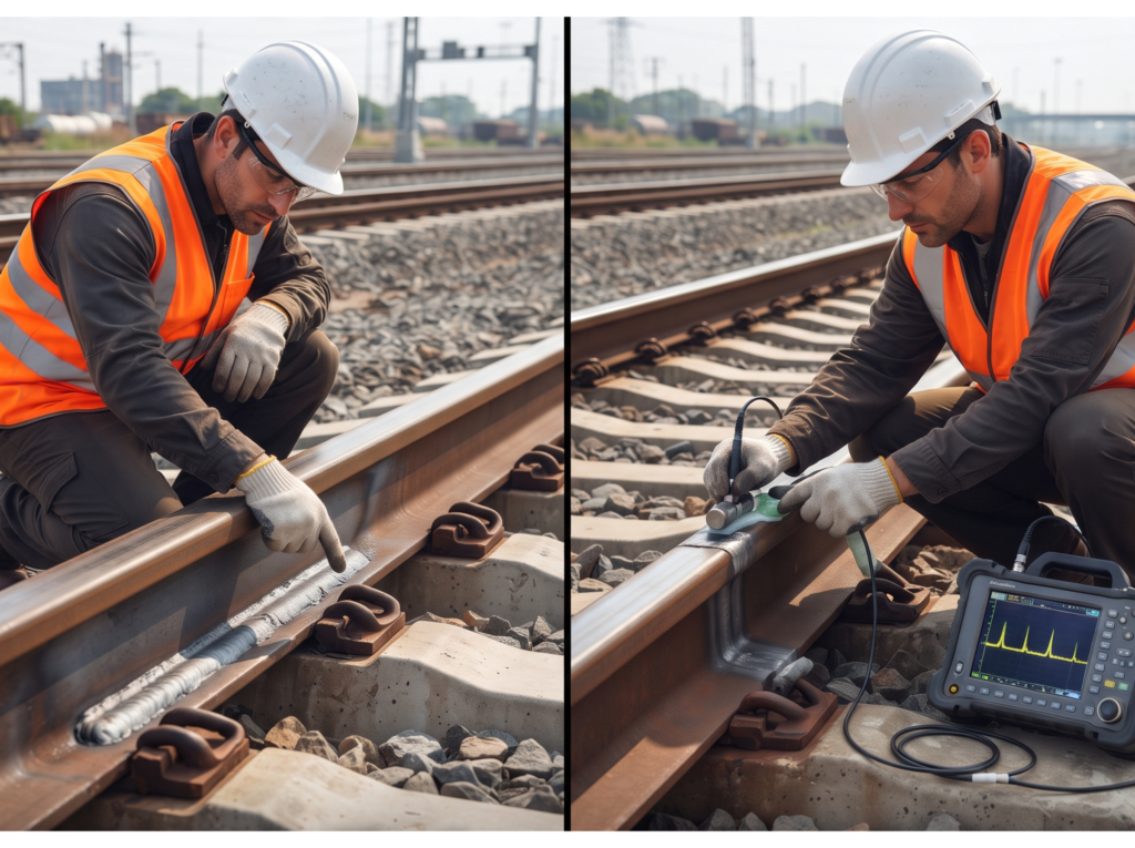
A weld can look perfectly sound and still hide a problem beneath the surface. Small changes in welding speed, heat, joint preparation, shielding, or consumable condition can leave behind imperfections that are not obvious during a routine visual check. This is why understanding weld defect types matters when the quality of a welded joint has to be verified rather than simply judged by its appearance.
Some problems are easy to spot. Undercut, excessive reinforcement, overlap, or a visible crack may be noticed during visual inspection. Others, such as lack of fusion, incomplete penetration, internal cracking, or inclusions, can remain hidden inside the joint. These weld defect types require a suitable NDT method to establish what is actually happening below the surface.
Ultrasonic testing (UT) is one of the methods used for that purpose. Instead of cutting a weld apart, an inspector sends high-frequency sound waves through the material and studies the returning signals. The result depends on more than the size of an indication. Its position, shape, orientation, and relationship to the ultrasonic beam can all change the response.
That is where proper UT technique becomes important. The following sections look at the defects inspectors commonly encounter and explain how ultrasonic testing helps find them.
What Causes Common Weld Defect Types?
Welding problems rarely result from a single factor. Several small process issues can combine to produce an unacceptable condition in weld defect types.
Common causes include:
· Incorrect current, voltage, or travel speed
· Poor groove preparation
· Incorrect root opening
· Contaminated base material
· Moisture in consumables or the welding environment
· Inadequate shielding gas coverage
· Insufficient cleaning between passes
· Incorrect preheat or interpass temperature
· Excessive restraint
· Poor welding sequence
· Inconsistent welding technique
For example, excessive travel speed can prevent sufficient heat from reaching the sidewall and contribute to lack of fusion. Poor interpass cleaning can leave slag between passes. An unsuitable root gap can contribute to incomplete penetration, while contamination or inadequate shielding can increase porosity.
Understanding the likely cause also helps inspectors interpret findings. A weld containing repeated indications in the same location across several joints may point toward a process problem rather than an isolated event.
But identifying the cause is only part of the job. The next challenge is recognizing the actual condition after welding has been completed.
How to Identify Weld Defects?
Identifying weld defect types begins with a systematic inspection rather than relying on appearance alone.
Visual testing (VT) normally provides the first assessment. Inspectors examine the weld profile, dimensions, reinforcement, undercut, overlap, visible cracking, surface porosity, arc strikes, and other accessible features. Surface condition and lighting can have a significant effect on the quality of a visual examination.
When a surface indication needs further investigation, magnetic particle testing (MT) can be used on suitable ferromagnetic materials to reveal surface and near-surface discontinuities. Liquid penetrant testing (PT) can identify surface-breaking discontinuities on suitable non-porous materials.
These methods have an important limitation: they cannot provide a complete picture of the weld interior.
Ultrasonic testing and radiographic testing can address that limitation. UT uses high-frequency sound waves to investigate material beneath the surface. RT uses penetrating radiation to create an image based on differences in material thickness and density.
The appropriate method depends on several factors:
1. Material type
2. Weld thickness
3. Joint configuration
4. Accessibility
5. Expected discontinuity
6. Required sensitivity
7. Applicable specification or code
A sensible inspection process therefore moves from surface examination to additional NDT when the application requires it. An indication can then be located, characterized, sized, and compared against the relevant acceptance criteria.
A surface can only reveal so much. The real question is how an inspection method can reveal a condition hidden inside the joint.
UT Weld Testing
An UT weld test sends high-frequency sound waves into a material and analyzes the energy that returns. A transducer introduces the ultrasonic pulse, while a couplant helps transfer sound efficiently between the probe and the inspection surface.
When the sound encounters a change in material structure or an interface, part of the energy can return toward the probe. A discontinuity can create such a reflection. The instrument displays the returning signal, and the inspector evaluates its amplitude, position, sound path, and movement as the probe travels.
Two broad approaches are especially relevant.
Straight-beam UT introduces sound approximately perpendicular to the inspection surface. It can be useful for assessing parent material and identifying laminations or other conditions that could affect a subsequent weld examination.
Angle-beam UT introduces sound into the material at an angle, commonly using shear waves. This arrangement allows the beam to travel through the weld region and reach areas such as the root and fusion boundaries.
Probe angles such as 45°, 60°, and 70° are commonly used in suitable applications, although the correct arrangement depends on the material, thickness, weld geometry, and inspection procedure. ISO 17640:2018 covers manual ultrasonic testing techniques for specified fusion-welded joints in metallic materials and defines testing levels associated with different probabilities of detection.
Calibration is another essential part of the process. Equipment settings, probe characteristics, reference standards, sensitivity, and scanning conditions must be established according to the approved procedure.
One principle matters more than almost anything else in weld UT: beam orientation.
A planar discontinuity can produce a strong response when the ultrasonic beam reaches its surface at a favorable angle. The same discontinuity may produce a weak response when the beam approaches it in an unfavorable direction.
This is why proper scanning requires more than one simple pass over a weld.
UT Detection Methods for Different Weld Defect Types
The response produced by weld defect types depends heavily on geometry and orientation.
A crack can produce a sharp reflection when the beam reaches an appropriate surface. Depending on the technique, diffracted signals from crack tips can also provide useful information. Multiple scan directions can help determine whether an indication behaves like a planar reflector.
Lack of fusion is particularly important during angle-beam inspection. Because the condition often follows a fusion boundary, a suitably oriented beam can produce a relatively strong indication. Scanning from another direction can provide additional information about the reflector.
Incomplete penetration generally requires careful attention around the weld root. Root geometry can create its own ultrasonic response, so the inspector must distinguish expected geometric signals from indications associated with an unfused region.
Slag inclusions may produce irregular or elongated signals. Their size, shape, location, and orientation can influence the response, making additional scanning useful when characterization is necessary.
Porosity behaves differently because individual pores are usually rounded. Small isolated pores may scatter ultrasonic energy and produce weaker responses. Larger pores or groups of pores can be easier to identify.
Undercut is primarily a surface or profile condition. Visual inspection often provides the clearest evidence, although the weld geometry can also produce ultrasonic responses that require interpretation.
| Defect | Typical UT response | Main consideration |
| Crack | Sharp reflection or diffraction | Orientation and sizing |
| Lack of fusion | Planar reflection | Scanning direction |
| Incomplete penetration | Root-area indication | Root geometry |
| Slag inclusion | Irregular or elongated response | Shape and position |
| Porosity | Scattered or multiple echoes | Size and grouping |
| Undercut | Possible geometric response | Visual confirmation |
This is why UT interpretation should never depend on signal amplitude alone. Probe movement, sound path, weld geometry, scanning direction, and the inspection procedure all contribute to the final assessment.
Conventional Angle-Beam UT
Conventional angle-beam UT remains an important technique for many welded-joint examinations.
The probe is positioned beside the weld and moved through a planned scanning pattern. The objective is to direct sound through the required weld volume and toward areas where discontinuities are most likely to occur.
Different beam angles provide different coverage. A lower angle may be useful for one region, while a higher angle may provide better access to another. The procedure determines which angles and scanning patterns are appropriate.
Scanning from more than one direction is particularly valuable for planar conditions. A lack-of-fusion indication may produce a strong response when approached from one direction and a much weaker response from another.
Probe position and sound path also help determine where an indication is located. Once a relevant response has been found, controlled probe movement can help establish its extent and support the required sizing method.
Good coupling, stable probe movement, suitable sensitivity, and proper calibration remain fundamental. Sophisticated equipment cannot compensate for poor inspection practice.
Advanced UT: PAUT and TOFD
Phased Array Ultrasonic Testing (PAUT) expands conventional UT by using multiple transducer elements controlled electronically. By changing the timing between those elements, the system can steer and focus sound across a range of angles.
That capability allows a weld to be examined from multiple beam angles without physically changing the probe for every angle. Recorded data can also be reviewed as images, which can make complex indications easier to analyze.
Time-of-Flight Diffraction (TOFD) works differently. Instead of relying primarily on the strongest reflected echo, the technique detects diffracted waves generated around the tips of suitable discontinuities. Travel-time measurements can then help establish the position and height of an indication.
TOFD is particularly useful for sizing suitable planar discontinuities. PAUT and TOFD can complement each other in demanding applications, with PAUT providing detailed coverage and imaging while TOFD contributes valuable sizing information.
FMC and TFM represent further developments in ultrasonic imaging. These approaches can provide detailed views of complex indications, although their suitability still depends on material, geometry, procedure, and inspection objectives.
The technology may change, but the fundamental requirement remains the same: the selected technique must suit the component and the discontinuity being investigated.
Matching the Inspection Method to the Defect
Different weld defect types call for different inspection strategies.
Visual testing can be highly effective for surface profile conditions. PT can reveal surface-breaking discontinuities on suitable non-porous materials, while MT can identify surface and near-surface indications in ferromagnetic components.
UT becomes particularly valuable when internal conditions require examination without damaging the component. PAUT and TOFD can add useful capabilities when detailed coverage or sizing is required. RT can also be valuable for certain volumetric conditions.
Method selection should consider:
· Material and thickness
· Weld configuration
· Accessibility
· Expected discontinuity
· Required sensitivity
· Governing standard
· Service conditions
No single NDT method is ideal for every situation. The strongest inspection program is the one that matches the method to the physical characteristics of the weld and the discontinuities that could realistically occur.
Detecting an indication, however, is not the final decision. The next stage determines what that indication actually means for weld acceptance.
From UT Indication to Weld Acceptance
A UT indication needs proper characterization before a final decision can be made.
The basic progression is:
Indication → characterization → sizing → evaluation → acceptance or rejection
This distinction matters. An ultrasonic response does not automatically mean that a weld has failed inspection. Geometric features can generate signals, and some discontinuities may remain acceptable when they fall within specified limits.
On the other hand, some conditions, particularly crack-like discontinuities, can receive very strict treatment regardless of their size.
ISO 23279 addresses the characterization of ultrasonic indications in welds, including consideration of whether indications are planar or non-planar.
Final Thoughts
Reliable weld inspection starts with understanding what can go wrong and selecting a method capable of finding the suspected condition. Weld defect types range from visible profile problems to hidden planar and volumetric discontinuities, and each interacts differently with an ultrasonic beam.
Conventional UT remains an important option for suitable welded joints, while PAUT and TOFD provide additional capabilities when inspection coverage, imaging, or sizing becomes more demanding. Yet equipment alone does not create a reliable inspection result. Calibration, scanning technique, surface condition, operator competence, documented procedures, and appropriate acceptance criteria all matter.
For fabrication and NDT programs, the goal is not simply to find weld defect types. The real objective is to identify, characterize, and evaluate relevant indications accurately enough to support a sound engineering decision and protect the component throughout its intended service life.
Key Takeaways
1. Weld defect types help inspectors select appropriate NDT methods for each application.
2. Cracks require careful evaluation because they can become serious stress-concentration points.
3. Lack of fusion often responds strongly when the ultrasonic beam reaches its plane.
4. Incomplete penetration usually requires focused examination around the weld root.
5. Porosity and slag inclusions can produce different ultrasonic responses because their shapes differ.
6. Conventional angle-beam UT remains valuable for many welded-joint inspection applications.
7. PAUT provides multiple beam angles, broad coverage, and useful inspection imaging capabilities.
8. TOFD can provide valuable sizing information for suitable planar weld discontinuities.
9. An ultrasonic indication requires characterization before a final acceptance decision.
10. Applicable codes and specifications determine whether detected discontinuities meet acceptance requirements.
Frequently Asked Questions
What are the 12 weld defect types?
Yes. Common weld imperfections include cracks, lack of fusion, incomplete penetration, porosity, slag inclusions, undercut, overlap, excessive reinforcement, burn-through, crater defects, arc strikes, and distortion. These weld defect types can develop for different reasons, including poor joint preparation, incorrect welding parameters, contamination, or unsuitable technique. The exact classification can vary by welding standard, so inspection reports should follow the terminology required by the applicable code.
What is the NDT test for welding?
Yes. Welding NDT includes several methods, such as visual testing, magnetic particle testing, liquid penetrant testing, ultrasonic testing, PAUT, TOFD, and radiographic testing. The most suitable method depends on the material, thickness, weld configuration, accessibility, and suspected discontinuity. UT is particularly useful for examining internal weld defect types without cutting or damaging the component, while surface methods can provide better results for accessible surface-breaking conditions.
How to identify a good weld?
Yes. A good weld should have the required dimensions, a consistent profile, suitable reinforcement, proper fusion, and no unacceptable visible imperfections. Visual inspection provides the starting point, but it cannot confirm every internal condition. Additional NDT may be necessary to evaluate weld defect types hidden beneath the surface. Final acceptance should always follow the applicable welding code, project specification, and inspection procedure rather than appearance alone.
What is an UT weld test?
Yes. An UT weld test uses high-frequency sound waves to examine the inside of a welded joint. A transducer sends ultrasonic energy into the material and receives returning signals from interfaces or discontinuities. The inspector studies signal strength, position, sound path, and probe movement to locate relevant weld defect types. Unlike destructive examination, UT can provide this information while leaving the inspected component intact.
