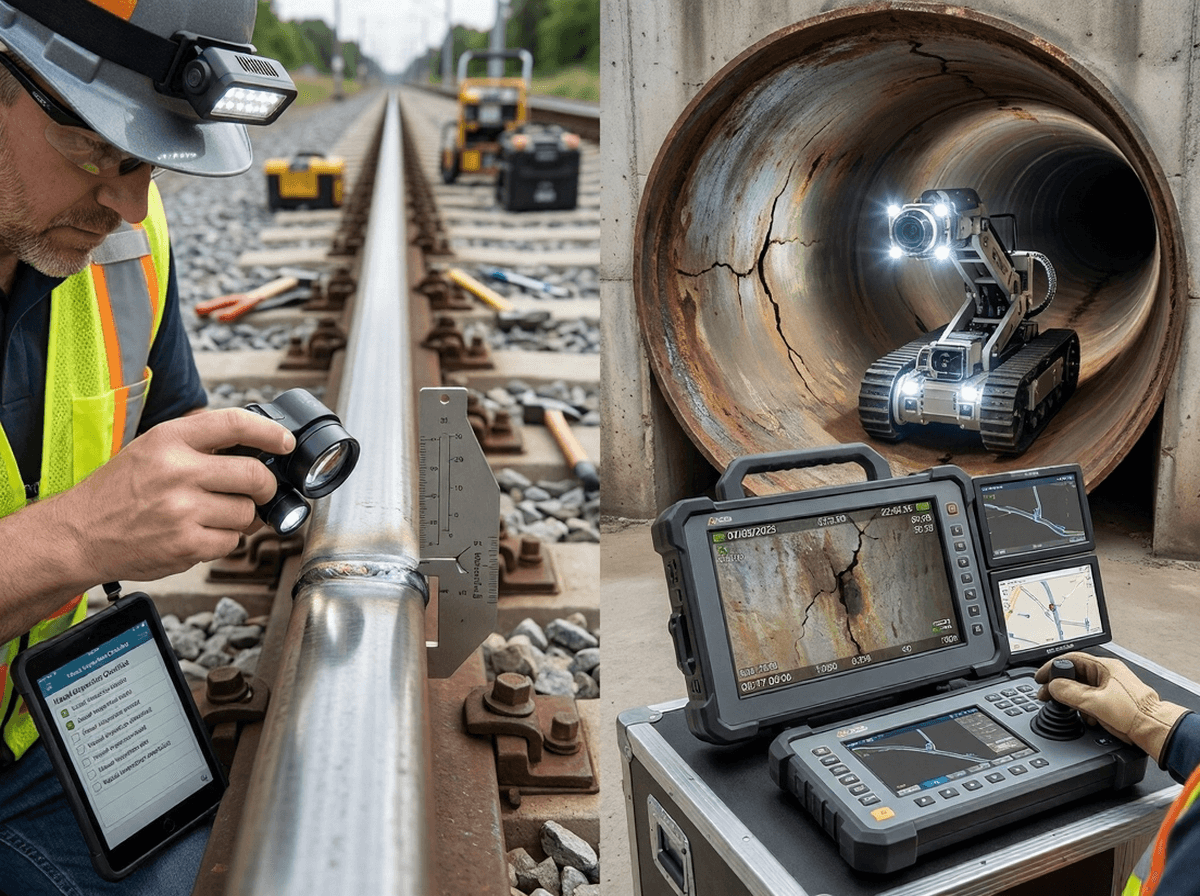
Visual testing (VT) is the NDT method in which a qualified inspector examines a weld or surface by eye or with optical aids. Under ASME Section V, Article 9, direct visual examination places the eye within 24 in. (600 mm) of the surface at an angle of at least 30°, with at least 100 foot-candles (1000 lux) of light on that surface.
For structural steel, the acceptance side is AWS D1.1. Its Clause 8 visual criteria (Table 8.1 in the 2020 and 2025 editions) reject any crack. They set undercut and porosity limits that change with static or cyclic loading. Every other NDT method on a structural job starts from the welds that have passed visual inspection, so this is the first test a weld must pass.
This guide is written for structural QA managers and buyers. It sets out the examination rules (ASME V), the acceptance rules (AWS D1.1), who may do the work (AWS QC1 and SNT-TC-1A), the tools, where VT fits before UT, MT and PT, and a worked static vs cyclic acceptance example. It also covers how visual inspection works on railroad track under 49 CFR 213.233, and what VT can't find.
Contents: examination vs acceptance · ASME V Article 9 · AWS D1.1 visual criteria · worked example · inspector qualification and vision · tools · VT before UT, MT and PT · VT on rail · limits · FAQ
What is visual testing, and which documents control it?
Visual testing is controlled by two kinds of document: an examination standard that says how to look, and an acceptance code that says what passes. Mixing them up is the most common error in VT specifications.
| Question | Document that answers it | Notes |
|---|---|---|
| How must the examination be done (distance, angle, light, remote aids)? | ASME BPVC Section V, Article 9, when the contract or code references it; ISO 17637 in ISO-based work | Section V sets methods, not acceptance criteria |
| What weld condition is acceptable in structural steel? | AWS D1.1/D1.1M, Clause 8 (visual acceptance table) | Static, cyclic and tubular columns |
| What is acceptable in pressure equipment or piping? | The construction code, e.g. ASME Section VIII or B31.3 | Not covered here |
| Who may accept welds under D1.1? | The inspector qualified under D1.1 Clause 8, normally an AWS CWI or SCWI certified under AWS QC1 | A CAWI works under a CWI |
| Who certifies NDT personnel for other methods? | The employer, under its written practice based on ASNT SNT-TC-1A or CP-189 | ASNT does not certify under SNT-TC-1A |
| How must railroad track be visually inspected? | 49 CFR 213.233 | Frequency and method, not weld acceptance |
ASME Section V is explicit that it "contains requirements and methods for nondestructive examination which are referenced and required by other BPVC Sections." It becomes binding on a structural job only if a contract or code points to it. Most structural specifications point to AWS D1.1 instead, which carries its own inspection clause.
Key takeaway: name both the examination procedure and the acceptance code in any VT purchase order. "VT per ASME V" alone has no reject criteria.
What does ASME Section V Article 9 require for direct visual testing?
Article 9 sets three conditions for direct visual examination: the eye within 24 in. (600 mm) of the surface, a viewing angle of at least 30° to the surface, and at least 100 fc (1000 lx) of light at the examination surface. The figures below are taken from consistent secondary reproductions of paragraph T-952 (study guides and code excerpts). Check them against the Section V edition your contract names. The current edition is 2025.
| Article 9 item | Requirement as commonly reproduced | Practical meaning |
|---|---|---|
| Direct VT distance (T-952) | Eye within 24 in. (600 mm) of the surface | Walking past a weld at arm's length plus does not count |
| Viewing angle (T-952) | Not less than 30° to the surface | Mirrors may be used to improve the angle |
| Illumination | Minimum 100 fc (1000 lx) at the examination surface, natural or supplemental white light | Measure at the weld, not at the lamp |
| Light verification | Light source, technique and light-level check demonstrated once, documented and kept on file (as reproduced) | Many written procedures add a light-meter check per shift |
| Magnification | Magnifying lenses permitted as aids | Doesn't relax the distance or light rules |
| Remote VT (T-953) | Mirrors, borescopes, fiberscopes, cameras; resolution at least equivalent to direct VT | Prove it on a resolution target before use |
| Translucent VT | Artificial light directed through a translucent laminate | For fiber-reinforced plastic laminates, not steel welds |
| Acceptance criteria | None | Comes from the referencing code |
The 100 fc figure is often quoted loosely as "recommended lighting". In Article 9 it is a minimum at the examination surface. For comparison, ISO 17637:2016, the ISO practice for visual testing of fusion-welded joints, sets a lower minimum of 350 lx and recommends 500 lx, with the eye within 600 mm. An inspector moving between ASME- and ISO-based jobs should not carry one figure over to the other.
What is remote visual testing?
Remote visual testing (RVT) is visual examination through an optical or video aid when the eye can't reach the 24 in. / 30° position. Typical cases are the inside of a pipe or hollow structural section, the back of a stiffener, a box girder interior or a weld behind an obstruction. Article 9 requires the remote system to resolve at least as well as direct viewing. In practice, the procedure demonstrates this on a fine-line or flaw target under the same lighting and distance that will be used on the part.
What is translucent visual testing, and does it apply to welds?
Translucent visual testing means shining artificial light through a translucent material, typically a fiber-reinforced plastic laminate, to show thickness changes, voids or dry spots inside it. Article 9 describes it as a technique alongside direct and remote VT, and EN 13018 likewise notes VT of translucent laminates. It has no use on steel welds, because steel transmits no light. The original version of this article presented it as a general technique for "plastics, glass and composites" without saying so. For structural steel, VT means direct and remote examination only.
Key takeaway: ASME V Article 9 tells you how to look and how bright the light must be. It never tells you whether a weld passes.
What are the AWS D1.1 visual acceptance criteria?
AWS D1.1:2025 puts inspection in Clause 8, and its visual acceptance table (Table 8.1) lists limits for cracks, fusion, craters, profile, undersize, undercut and porosity, with separate columns for statically loaded nontubular, cyclically loaded nontubular and tubular connections. The current publication is D1.1/D1.1M:2025, now listed by AWS as D1.1/D1.1M:2025-AMD1. AWS describes the 2025 edition as bringing "Refined acceptance criteria and inspection guidance," so check every value below against the edition named in your contract.
The values below come from CWI study guides and AWS forum reproductions of the 2015–2020 wording. They are hedged accordingly and must be confirmed by a CWI before use.
| Criterion | Statically loaded nontubular | Cyclically loaded nontubular |
|---|---|---|
| Cracks | Any crack unacceptable, regardless of size or location | Same |
| Fusion | Thorough fusion between adjacent layers and between weld and base metal | Same |
| Crater cross section | All craters filled to the full weld cross section (except ends of intermittent fillets outside their effective length) | Same |
| Weld profile | Per the Clause 7 profile requirements | Same |
| Undersized fillet welds | May underrun nominal size by 1/16 in. (3/16 in. weld), 3/32 in. (1/4 in. weld) or 1/8 in. (5/16 in. and larger) for no more than 10% of the weld length; none at web-to-flange girder ends for twice the flange width | Same |
| Undercut, material under 1 in. | Max 1/32 in. (0.8 mm); up to 1/16 in. (1.6 mm) allowed for an accumulated 2 in. in any 12 in. | Primary members, weld transverse to tensile stress: max 0.01 in. (0.25 mm). All other cases: max 1/32 in. |
| Undercut, material 1 in. and thicker | Max 1/16 in. for any length | As above |
| Piping porosity, CJP butt joints transverse to tensile stress | None visible | None visible |
| Piping porosity, all other groove and fillet welds | Sum of visible pore diameters (1/32 in. and larger) max 3/8 in. in any linear inch and 3/4 in. in any 12 in. | Fillets: max one pore in each 4 in. of length, max diameter 3/32 in. |
| Time of inspection | After cooling to ambient; 48 h delay for A514, A517 and A709 Grade HPS 100W (wording varies by edition) | Same |
Read the table with three cautions.
- The loading column decides the answer. The same 0.03 in. undercut passes on a statically loaded building beam and fails on a crane runway girder weld transverse to tension. Never quote a D1.1 visual limit without the loading condition. The contract drawings, not the inspector, define which members are cyclically loaded.
- The 3/32 in. pore diameter is a cyclic limit. On static structures D1.1 uses a sum-of-diameters rule, and drafts often quote 3/32 in. as a general limit.
- The 2025 edition reportedly rewrote some items. One study guide reports a length-based porosity rule for welds under 12 in. long (sum of diameters no more than 0.06 × weld length), and one vendor summary claims undercut limits now depend on weld length and base-metal thickness. Neither claim was confirmed from AWS text. If your contract cites D1.1:2025, read Table 8.1 itself.
D1.1 itself requires only visual inspection unless the contract adds other NDT. Requirements for UT of CJP welds usually come from AISC 360 Chapter N or AISC 341 through the contract documents. For the full D1.1 inspection picture, including UT rating, see our guide to AWS D1.1 weld inspection criteria. For how each discontinuity forms, see our pages on weld defect types, porosity in welding and lack of fusion.
Key takeaway: a D1.1 visual limit is meaningless without its loading column and its edition.
Worked example: does this fillet weld pass visual testing under static and cyclic loading?
The same weld can pass under the static column and fail under the cyclic column. This example uses the pre-2025 Table 8.1 values in the table above. Treat it as a method, and re-run it with the values in your contract edition.
The weld: a 5/16 in. fillet weld, 24 in. long, joining a 3/4 in. (19 mm) plate to a flange. Base metal is under 1 in. thick, so the thinner-material undercut rule applies. The inspector measures with a calibrated undercut depth gauge and a fillet gauge, at 100 fc or more, with the eye within 24 in.
Findings (positions measured from the start of the weld):
| Finding | Location | Measured |
|---|---|---|
| Undercut A | 2.0–3.5 in. | 0.040 in. deep, 1.5 in. long |
| Undercut B | 15.0–18.0 in. | 0.020 in. deep, 3.0 in. long |
| Pore cluster | 8.2, 8.5 and 8.8 in. | 3 pores, each 1/16 in. (0.0625 in.) diameter |
| Single pore | 20.0 in. | 1 pore, 1/16 in. (0.0625 in.) diameter |
| Undersize | 10.0–12.0 in. | Leg 1/4 in. on a 5/16 in. nominal, 2.0 in. long |
Case 1: statically loaded member.
- Undercut A: 0.040 in. exceeds the general 1/32 in. (0.031 in.) limit. It is within the 1/16 in. (0.0625 in.) allowance, and its 1.5 in. length is under the 2 in. allowed in any 12 in. No other undercut deeper than 1/32 in. falls in the same 12 in. window, because B is shallower. Accept.
- Undercut B: 0.020 in. is at or below 0.031 in. Accept.
- Porosity, any linear inch: the cluster spans 8.2–8.8 in., so all three pores fit in one inch. 3 × 0.0625 = 0.1875 in., under the 3/8 in. (0.375 in.) limit. Accept.
- Porosity, any 12 in.: the worst window, 8.2–20.2 in., holds all four pores. 4 × 0.0625 = 0.25 in., under the 3/4 in. (0.75 in.) limit. Accept.
- Undersize: 5/16 − 1/4 = 1/16 in. underrun, within the 1/8 in. allowance for a 5/16 in. weld. The length allowed is 10% × 24 in. = 2.4 in., and 2.0 in. is under that. Accept, provided the undersize isn't at a girder-end zone where none is allowed.
Result, static: the weld is acceptable.
Case 2: cyclically loaded primary member, weld transverse to tensile stress.
- Undercut A: 0.040 in. against the 0.01 in. limit. Reject.
- Undercut B: 0.020 in. against the 0.01 in. limit. Reject.
- Porosity frequency: the cyclic fillet rule allows at most one pore in each 4 in. of length. The cluster puts three pores within 0.6 in. Reject.
- Porosity diameter: each pore is 0.0625 in., under the 3/32 in. (0.094 in.) cap. The single pore at 20.0 in. is more than 4 in. from the cluster and passes on its own.
- Undersize: same as static. Accept.
Result, cyclic: reject. The fix is to repair both undercuts and the pore cluster under an approved repair procedure, then re-inspect visually. If the same member were cyclic but the weld were not transverse to tensile stress, the undercut limit would be 1/32 in. Undercut A (0.040 in.) would still reject, and B (0.020 in.) would pass.
| Check | Static result | Cyclic (transverse) result |
|---|---|---|
| Undercut A, 0.040 in. | Accept (≤1/16 in., 1.5 in. ≤ 2 in. per 12 in.) | Reject (> 0.01 in.) |
| Undercut B, 0.020 in. | Accept (≤ 1/32 in.) | Reject (> 0.01 in.) |
| Porosity per inch, 0.1875 in. | Accept (≤ 0.375 in.) | Not the cyclic test |
| Porosity per 12 in., 0.25 in. | Accept (≤ 0.75 in.) | Not the cyclic test |
| Porosity frequency, 3 in 0.6 in. | Not the static test | Reject (> 1 per 4 in.) |
| Pore diameter, 0.0625 in. | — | Accept (≤ 0.094 in.) |
| Undersize, 1/16 in. over 2.0 in. | Accept (≤ 1/8 in., ≤ 2.4 in.) | Accept |
| Weld disposition | Accept | Reject and repair |
The depths are physically sensible: 0.040 in. of undercut is about 5% of the 0.75 in. plate. An undercut reading should always be checked against the plate thickness before it is reported.
Who is qualified to perform visual weld inspection?
Under AWS D1.1, visual acceptance is normally made by an AWS Certified Welding Inspector (CWI) or Senior CWI, certified by AWS under AWS QC1. NDT personnel for other methods are certified by their employer under SNT-TC-1A or CP-189. The two routes are separate, and a buyer should ask for the right one.
- AWS QC1 is the AWS Specification for AWS Certification of Welding Inspectors. AWS currently lists QC1:2016-AMD1, with B5.1:2025 for welding inspector qualification. AWS states that CWI candidates "must pass a vision test" and meet education and experience requirements.
- D1.1 Clause 8 qualification. A 2025 study guide lists current CWI or SCWI certification, CWB certification, or another person the Engineer approves, as qualifying under Clause 8. A CAWI (Certified Associate Welding Inspector) works under a CWI or SCWI, and the CWI decides acceptance.
- SNT-TC-1A is ASNT's recommended practice. The employer writes a practice and certifies its own Level I, II and III staff. ASNT doesn't certify anyone under it. ANSI/ASNT CP-189 is the standard version of the same employer-based model.
- ISO 9712 third-party certification exists for VT, but its scope excludes direct unaided VT, and it is optional in US structural work.
What vision tests do visual inspectors need?
A visual inspector needs proof of near-vision acuity, usually Jaeger J2 at 12 in., and a color perception or color-contrast test. The interval depends on the scheme.
| Scheme | Near vision | Color | Interval |
|---|---|---|---|
| AWS CWI (QC1 and AWS form) | Jaeger J2 at 12 in. (30.5 cm) or more, natural or corrected | Color perception test, result recorded | At certification; a study guide gives every 3 years, AWS forms use a 7-month or 1-year window before the exam or expiry (CONFIRM with AWS) |
| D1.1 Clause 8 (2025, per study guide) | Jaeger J2 at 12–17 in. (300–430 mm) | Ability to distinguish colors (e.g. Ishihara plates) | Every 3 years (as reported) |
| SNT-TC-1A employer practice | Jaeger No. 2 or equivalent at not less than 12 in., in at least one eye | Color contrast differentiation | Near vision annually; color interval varies by edition and practice (annual in some practices, up to 5 years in others) |
The SNT-TC-1A figures are a recommended baseline. The employer's written practice is what actually binds the technician, and many practices are stricter. A buyer should ask for a current eye-test record with each inspector's certification, not just the certificate.
What tools are used for visual testing of welds?
Visual weld inspection needs measuring tools as much as eyes, because most D1.1 visual limits are dimensions. A CWI's kit for structural work typically includes the following.
| Tool | Measures or shows | Note |
|---|---|---|
| Fillet weld gauge set | Leg size, concave or convex profile | Checks the undersize allowance |
| Bridge cam (multi-purpose) weld gauge | Undercut depth, reinforcement, throat, misalignment, angle of preparation | Most common single tool on site |
| Undercut depth gauge (dial or digital) | Undercut to 0.001 in. | Needed for the 0.01 in. cyclic limit |
| Calibrated light meter | Illumination at the examination surface | Proves the 100 fc (1000 lx) minimum |
| Magnifier (typically 5×–10×) and flashlight | Crack confirmation, crater cracks, oblique lighting | Aids; don't replace the light requirement |
| Inspection mirror | Back side of a joint, restricted access | Counts as direct VT under Article 9 |
| Borescope, fiberscope or videoscope | Pipe and box interiors, root side of closed joints | Remote VT; demonstrate resolution first |
| Camera with scale | Records each rejectable indication | Supports the inspection report |
| Thermometer or temperature crayons | Preheat and interpass during in-process VT | Part of before- and during-welding checks |
On site, the undercut gauge most often decides a cyclic job. The 0.01 in. limit is roughly the thickness of a sheet of paper, and it can't be judged by eye. A bridge cam gauge that reads only in 1/64 in. steps can't show it either. When a project has cyclically loaded members, ask whether the inspector's undercut gauge resolves 0.001 in.
Why is visual testing done before UT, MT and PT?
Visual testing comes first because any other NDT method on a weld that has failed visual inspection is wasted, and because surface condition controls whether UT, MT and PT results are valid. A visual check before, during and after welding catches most fit-up and workmanship problems at the lowest cost.
| Stage | What the visual inspector checks | Why it matters for later NDT |
|---|---|---|
| Before welding | Joint fit-up, root opening, bevel, cleanliness, WPS on hand, welder qualified | Bad fit-up causes lack of fusion that only UT will find later |
| During welding | Preheat and interpass, cleaning between passes, bead placement, WPS variables | In-process VT is the only check on interpass cleaning |
| After welding | Table 8.1 items: cracks, fusion, craters, profile, size, undercut, porosity | Defines which welds go forward to UT, MT or PT |
| Before UT | Spatter and roughness on the scanning surface removed, profile allows probe contact | Rough surfaces lose coupling and hide near-surface echoes |
| Before MT or PT | Clean surface, no paint or scale over the weld toes | Surface methods need open discontinuities |
Under D1.1, the time of inspection rule also applies to later NDT. For some quenched-and-tempered steels (A514, A517, A709 HPS 100W), final inspection waits 48 hours after the weld cools, because of the risk of delayed hydrogen cracking. Forum sources report that D1.1 evaluates MT and PT indications against the visual acceptance criteria. That reading is unconfirmed, so confirm it in the edition named in your contract.
Each method then finds what visual inspection can't. MT finds surface and near-surface cracks in ferromagnetic steel. PT finds surface-breaking discontinuities in any non-porous material. UT finds internal lack of fusion, slag and cracks through the thickness. See our comparison of NDT methods, our magnetic particle examination page and our guide to liquid penetrant testing.
Key takeaway: if a weld fails VT, repair it before you pay for UT.
How is visual inspection used on railroad track?
On railroads, visual inspection of the track structure is a federal requirement under 49 CFR 213.233. It sets how often track must be walked or ridden and how the inspection is made. It does not set weld acceptance criteria. Section 213.233(b) reads:
"Each inspection shall be made on foot or by traversing the track in a vehicle at a speed that allows the person making the inspection to visually inspect the track structure for compliance with this part."
The same paragraph limits an inspection vehicle to 5 mph over crossings and turnouts. Other track inspection devices may "supplement visual inspection" but don't replace it. The required frequency in 213.233(c) depends on track class and traffic.
| Track (213.233(c)) | Minimum visual inspection frequency |
|---|---|
| Excepted track and Class 1–3 main track and sidings | Weekly, at least 3 calendar days apart |
| Same track, if passenger trains run or it carried over 10 MGT the previous year | Twice weekly, at least 1 calendar day apart |
| Other excepted and Class 1–3 track | Monthly, at least 20 calendar days apart |
| Class 4 and 5 track | Twice weekly, at least 1 calendar day apart |
Three distinctions matter for rail work. First, visual track inspection under 213.233 is separate from internal rail testing under 213.237. A track inspector can see a broken weld, a joint gap or a battered rail end, but can't see a transverse defect growing inside the head. Second, AWS D1.1 doesn't govern thermite or flash-butt welds in track. Their acceptance comes from the railroad's own specifications, the welding supplier's procedure and AREMA practice. Third, rail transit systems not connected to the general railroad system fall under state safety oversight rather than Part 213. For how a 213.233 inspection is planned and recorded, see our guide to regular railway track inspections.
What are the limits of visual testing?
Visual testing only finds what reaches the surface and is large enough to see under the lighting used. It gives no depth for cracks and no information about the weld interior. A clean VT report doesn't mean a sound weld.
| Limitation | Why | What to add |
|---|---|---|
| Internal discontinuities | Lack of sidewall fusion, slag, internal porosity and root defects in closed joints are invisible from outside | UT (or RT) where the contract requires it |
| Tight cracks | Fine cracks at the toe, or under mill scale, paint or spatter, may not show at 100 fc | MT on ferritic steel, PT elsewhere, after cleaning |
| Crack depth | VT shows length, never depth | UT sizing, or grind-out during repair |
| Subsurface porosity | Only surface-breaking ("piping") pores count under D1.1 visual rules | UT or RT if internal soundness matters |
| Inspector dependence | Results depend on vision, training, fatigue and lighting | Vision records, written procedure, light-meter checks |
| Access | Inside closed sections and pipe the 24 in. / 30° rule can't be met | Remote VT with demonstrated resolution |
| Coatings | Paint and galvanizing hide toe cracks and undercut | Inspect before coating |
The original version of this page claimed inspectors detect "more than 70% of visible structural defects" in initial inspections. No source for that figure exists, so it has been removed. Published VT reliability depends heavily on the defect type, the lighting and the inspector, and no single detection rate applies to all of them.
How EMA Industries applies this
EMA Industries performs AWS D1.1 structural weld UT, MT and PT, NDT Level III services and WPS/PQR work. We're based in Southern California and mobilise nationwide. Before UT, MT or PT, we record the visual condition of each weld and the scanning surface, and in each report we state which acceptance code, edition and loading column were applied. Without that, a static and a cyclic weld can't be told apart later. To scope weld inspection on a structural project, see our ultrasonic examination services or contact us.
Related reading: AWS D1.1 weld inspection criteria · Weld defect types · Porosity in welding · Comparison of NDT methods · Regular railway track inspections
Frequently asked questions
What light level is required for visual weld inspection?
ASME Section V Article 9 requires at least 100 foot-candles (1000 lux) at the examination surface for direct visual examination. ISO 17637 sets a lower minimum of 350 lux and recommends 500 lux. Use whichever document your contract names, and measure the light at the weld with a calibrated meter.
How close must the inspector's eye be for direct visual testing?
Within 24 in. (600 mm) of the surface, at an angle of not less than 30° to it, under ASME V Article 9 as commonly reproduced. Where that position can't be reached, the examination becomes remote visual testing with mirrors, borescopes or cameras of equivalent resolution.
Who can accept welds visually under AWS D1.1?
Normally an AWS CWI or SCWI, or another person qualified under D1.1 Clause 8 and accepted by the Engineer. A CAWI can perform inspections under a CWI's supervision, but the CWI makes the acceptance decision.
What vision test does a welding inspector need?
A near-vision test showing Jaeger J2 at 12 in. or more (with or without corrective lenses) plus a color perception test. AWS sets the interval for CWIs. SNT-TC-1A practices usually require near vision annually. Check the current AWS form and your employer's written practice.
Does visual testing find internal weld defects?
It doesn't. Visual testing sees only surface-breaking features and weld shape. Internal lack of fusion, slag and porosity need UT or RT, and tight surface cracks are best confirmed with MT or PT.
What is the ISO standard for visual inspection of welds?
ISO 17637:2016, Non-destructive testing of welds – Visual testing of fusion-welded joints. It covers how to examine. Acceptance levels for the imperfections found come from ISO 5817 (the 2014 edition was withdrawn in 2023) or the application standard.
Sources
- ASME BPVC Section V, Nondestructive Examination, ASME product page (2025 edition)
- AWS D1.1/D1.1M:2025-AMD1, Structural Welding Code – Steel, American Welding Society
- AWS Certified Welding Inspector (CWI), AWS certification page (QC1:2016-AMD1, B5.1:2025, vision test)
- AWS QC1, Specification for AWS Certification of Welding Inspectors, AWS
- ASNT standards: SNT-TC-1A and ANSI/ASNT CP-189, ASNT
- 49 CFR 213.233, Track inspections, eCFR (text read on Cornell LII, October 2026)
- ISO 17637:2016, Visual testing of fusion-welded joints, AFNOR store listing
- AWS D1.1 Table 8.1 visual acceptance and Clause 8 inspector qualifications, open-exam-prep study guides (secondary)
- ASME V Article 9 VT summary and ASNT Level III visual testing guide, open-exam-prep study guides (secondary)