

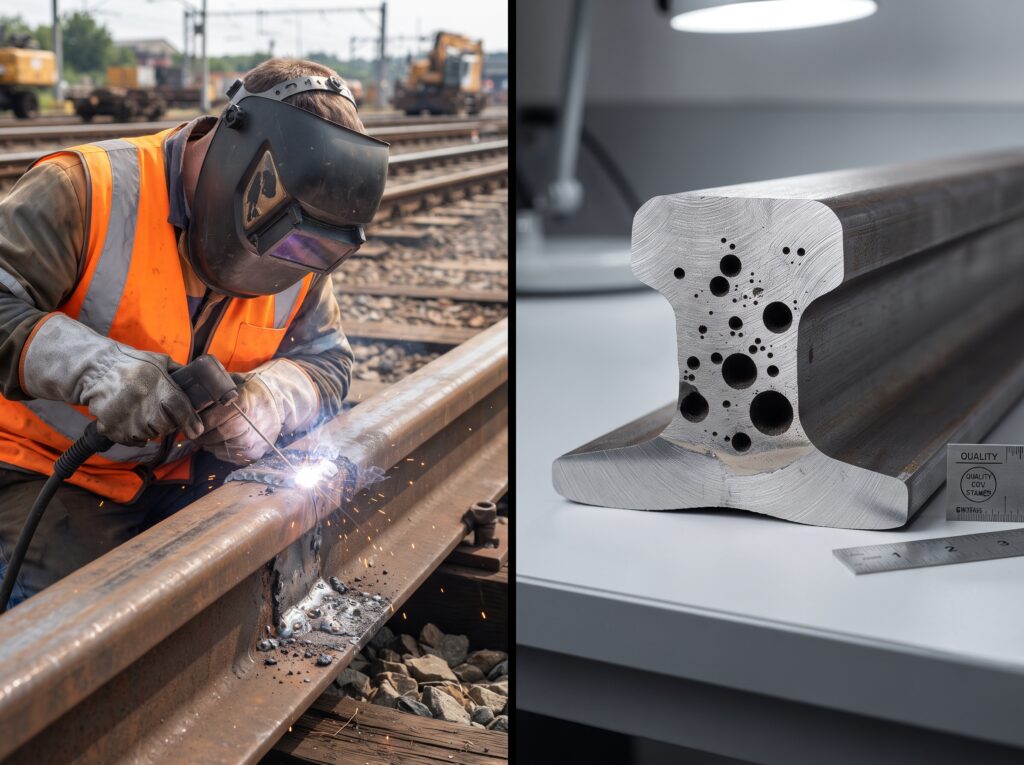
Porosity in welding shows up everywhere. Fabrication shops see it constantly. Manufacturing floors know it well. When gas gets trapped inside molten metal as everything cools down, that’s your porosity in welding problem right there.
Here’s what matters: pores don’t have to ruin your welds. Most of the time, porosity in welding has a cause. A controllable cause. That means you can prevent it.
So before you even run an inspection, start earlier. Think about what makes these gas cavities form in the first place. Learn what conditions create them. Then this is the key part to figure out how to actually stop the process from making porosity in welding happen. When it still happens anyway, non-destructive testing steps in and tells you where those internal pores are hiding and how deep they go.
The Mechanics of Porosity in Welding
Gas bubbles form when molten metal touches atmospheric gases, shielding systems, consumables, coatings, and contaminated surfaces. That molten pool runs hot. Hot enough to react with just about anything nearby.
Bubble forms. Maybe it escapes during cooling. Maybe it doesn’t.
The ones that stick around? They become pores.
Three gases matter most: hydrogen, nitrogen, and oxygen. Moisture and contaminants can sneak these into your weld during heating. Shielding issues. Moisture again. Surface contamination. Coatings. Gas-line problems. These aren’t rare edge cases they’re the main culprits behind porosity in welding.
The sequence is straightforward. A gas source reaches the pool. Gas absorbs into the metal or forms bubbles. Bubbles try to escape. But then? Solidification traps whatever’s left. And there’s your defect. Small. Spherical. Or maybe elongated. Could be a cluster. Might break through the surface entirely.
The real takeaway: you can’t prevent porosity in welding by tweaking one thing. The gas could come from your material, your consumables, the environment, your equipment, or your technique. Find the actual source rather than keep fixing the visible symptom.
Types You’ll Encounter
Single or scattered pores. These are isolated cavities spread randomly throughout the weld. You see one here, another there.
Clusters. Multiple pores squeezed into one small region.
Aligned pores. Follow a recognizable path. Usually signals a recurring process issue or contamination problem.
Surface pores. Break right through to the surface. Sometimes you can spot these with your eyes during visual inspection.
Wormhole porosity in welding. Has that tunnel-like, elongated look to it.
Crater porosity. Forms around where the weld ends. Bad solidification at the termination area leaves a cavity behind.
Distribution matters just as much as individual pores, honestly. One tiny pore? Different story than a massive cluster or a line of elongated cavities. When you inspect, look at size, number, spacing, location, and pattern. Treat every gas cavity as unique because they kind of are.
What Triggers Porosity in Welding
Shielding Gas Goes Wrong
The shielding system has one job: keep the atmosphere away from that molten pool. When the gas doesn’t cover properly, nitrogen and oxygen from the air slip in.
What causes this breakdown? Insufficient flow. Wrong gas choice. Leaks. Drafts. Torch too far away. Turbulence in the gas itself.
More gas doesn’t automatically mean better protection. Crank up the flow too high and you get turbulence that pulls surrounding air into your shielding envelope. A clogged nozzle? Same problem. Uneven coverage follows.
Moisture and Contaminated Materials
Damp electrodes. Wet fluxes. Filler materials sitting exposed to humidity. Joint surfaces that aren’t dry.
All of these introduce hydrogen during welding. Which means consumables need proper storage. Proper handling. Everything spelled out in the procedure.
Filler material contamination works the same way. Oil on the surface. Grease. Paint. Adhesive residue. Dirt. Heat these up and they vaporize. Release gases. The welding area looks spotless, but that contaminated filler keeps pumping defects into your weld. And you’ll see porosity in welding as a result.
Surface Contamination Gets Overlooked
A clean joint is your foundation. Oil, grease, rust, scale, paint, primers, zinc coatings all of these release gases or block fusion.
Joint geometry matters too. Crevices trap gas. Confined areas trap gas. Poor fit-up? Gas gets trapped. Open roots? Same story. Atmospheric air finds its way in from unexpected directions.
Parameters and Technique
Speed matters. Too fast and gas doesn’t have time to escape before the metal solidifies. Porosity in welding results.
Current, voltage, arc length, torch angle, electrode position. Any of these get wrong and you’re disturbing the weld pool and your shielding coverage simultaneously.
Start and stop technique deserves attention too. Terminate the arc abruptly and you leave a crater. That crater doesn’t fill or solidify right. Localized cavity forms.
Consistency prevents this. Qualified parameters. Qualified technique.
Environmental Conditions Sneak Up On You
Wind. Drafts. They’ll wreck your shielding even when the flowmeter looks perfect.
Outdoor welding? Needs wind protection. Needs attention to local airflow. A stable environment lets your shielding do what it’s supposed to do.
Here’s the broader pattern: porosity in welding rarely comes from one thing going wrong. It shows up when several small controls fail at the same moment. Multiple failures. That’s when you get trapped gas. That’s when you get porosity in welding problems that cost time and money.
Prevention: The Multi-Step Approach
Before the Arc Starts
Clean your base materials. Remove oil, grease, dirt, rust, scale, paint. Everything comes off.
Joint fit-up needs to match your approved procedure. Surfaces stay protected from moisture before welding begins.
Consumables? Store them right. Dry them if needed. Handle them according to what the manufacturer says and what your procedure demands.
Your shielding system deserves attention too. Gas cylinders. Regulators. Hoses. Connections. Nozzles. Run routine checks. Catch problems early.
During Welding
Shielding gas coverage should stay stable the entire time. Correct gas. Correct flow rate. Avoid excessive flow it creates turbulence.
Keep the nozzle clean. Keep torch distance and angle within qualified range.
Travel speed needs to be appropriate. Arc length. Current. Voltage. These all affect whether gas escapes or becomes porosity in welding.
Between passes, remove slag and contamination. Don’t let later weld metal trap additional gas or contaminants and create more porosity in welding.
Environmental control enters here. Wind barriers for outdoor work. Keep the area as dry and clean as practical.
After Welding
Visual exam picks up surface pores, pinholes, crater problems. Recurring defects? That’s a signal. Don’t just keep repairing locally and investigate the process.
Records help. Document your weld parameters. Note your consumables. Track environmental conditions. Log inspection results. Patterns emerge.
Modern weld cameras and audio-based monitoring can provide real-time signals about process disturbances and possible porosity in welding formation. These complement established inspection and quality procedures rather than replace them.
Why You Still Need Inspection
Perfect process control doesn’t guarantee zero internal defects. Critical welds need non-destructive examination. You need verification that internal quality is sound.
Visual testing handles surface-breaking conditions. Penetrant testing reveals surface pores on suitable materials. Magnetic particle testing finds surface and near-surface indications in ferromagnetic materials. Radiographic testing shows internal volumetric discontinuities. Ultrasonic testing provides information about internal reflectors and their location and depth.
The method depends on your material, thickness, geometry, defect type, accessibility, and what the specification requires. Radiography generally beats conventional ultrasonic testing for detecting porosity in welding because radiography specializes in volumetric discontinuities. But that doesn’t make UT worthless. Far from it.
Ultrasonic Testing and Porosity in Welding
High-frequency sound enters the component through a transducer. That sound encounters a boundary with different acoustic properties. Energy bounces back toward the transducer. The equipment displays the response as an indication. You evaluate.
Simple path: Transducer → weld metal → discontinuity → reflected sound → receiver → displayed indication.
A pore scatters or reflects ultrasonic energy depending on size, shape, position, orientation, and surrounding weld metal characteristics. The response varies considerably. Large cavity produces a stronger response than a tiny pore. A cluster creates a broader or complex indication.
A-scan displays signal amplitude against time or sound path. Initial pulse appears first. Discontinuity responses appear later. Back-wall echo provides your reference for the sound path.
But here’s the limitation: an ultrasonic indication doesn’t automatically mean you’ve found porosity in welding. Cracks create signals. Lack of fusion creates signals. Inclusions. Geometry effects. Other reflectors. The inspector has to consider probe position, beam angle, weld geometry, signal behavior, scanning direction, calibration, and the approved evaluation procedure.
Porosity in welding gets tricky when pores are very small and scattered widely. Rounded gas cavities don’t give the same strong, directional reflection you’d get from a large planar reflector. Weld microstructure attenuates sound. Creates background noise. This is why UT needs a procedure designed for your material, thickness, weld configuration, and inspection objective.
Can Phased Array Improve Things?
Phased array ultrasonic testing uses multiple transducer elements. These steer and focus the beam electronically. Instead of one fixed beam, PAUT collects information from several angles. Results appear as images or datasets.
For porosity in welding assessment, PAUT helps locate indications, visualize clusters, improve coverage. But advanced imaging doesn’t change the fundamental physics. Very small pores still produce weak or complex responses. Interpretation still requires proper calibration, procedures, equipment, and skilled personnel.
UT Versus RT: Which One?
Choose based on your inspection objective, not preference.
Radiography provides strong evidence of volumetric discontinuities. Makes pore distribution easier to visualize. Ultrasonic testing provides depth and location information. Can often inspect from one accessible side. Avoids ionizing-radiation controls associated with radiography.
When porosity in welding is your principal concern? RT often provides better characterization. When internal location, depth, or other discontinuity types matter? UT often provides advantages. Project specifications may also dictate which method you use.
When Porosity in Welding Gets Accepted
Detection doesn’t automatically equal rejection. Acceptance hinges on your governing code or specification.
Pore size matters. Number of pores. Spacing. Distribution. Alignment. Location. Weld thickness. Required quality level. All of these factor in.
ISO 6520-1 classifies weld imperfections. ISO 5817 establishes quality levels for fusion-welded joints. But your project specification, construction code, or contract requirement? That’s what actually controls the acceptance decision.
Repair: The Right Way
Detect → Evaluate → Accept or Reject → Repair If Needed → Re-Inspect.
Localized unacceptable porosity in welding gets removed through grinding or gouging. Then cleaning. Then controlled rewelding. Widespread porosity in welding signals a systemic process problem. Might need extensive removal. Might require complete weld removal and re-preparation.
The crucial part: repair must address the original cause. Rework the same weld under the same conditions and you’ll reproduce the same defect. That’s not repair. That’s spinning your wheels.
Final Thoughts
Porosity in welding becomes manageable when you treat it as a process problem, not just an inspection finding.
Combine these: clean joint preparation, dry consumables, stable shielding, suitable welding parameters, controlled environmental conditions, qualified welding practices. This combination works.
When internal defects remain possible, non-destructive testing verifies that controls actually worked. Radiography handles volumetric discontinuities effectively. Ultrasonic testing provides depth and location information about indications. PAUT extends coverage and visualization, but conventional UT and PAUT both require sound procedures and skilled interpretation.
The lesson: prevention stops gas from getting trapped. Inspection confirms your controls worked. Combine disciplined welding-process control with appropriate non-destructive testing. That’s your path to reliable weld quality and lower risk from porosity in welding.
Key Takeaways
- Porosity in welding occurs when gas becomes trapped inside molten weld metal during solidification
- Moisture, contamination, poor shielding, and incorrect welding parameters drive porosity in welding
- Proper surface cleaning cuts the risk of trapped gas dramatically
- Correct shielding-gas flow prevents atmospheric gases from entering the molten pool
- Dry electrodes, fluxes, and filler materials control moisture-related porosity in welding
- Scattered, clustered, aligned, surface, wormhole, and crater forms each have distinct characteristics
- Visual inspection catches surface pores but misses buried internal porosity in welding
- Radiographic testing excels at detecting volumetric weld discontinuities
- Ultrasonic testing locates internal indications and provides depth information
- Repair procedures must remove unacceptable defects and fix the original welding-process cause
FAQs
What are the types of porosity in welding?
Four forms commonly come up: scattered, clustered, linear or aligned, and surface. Scattered porosity consists of individual pores spread through the weld. Clustered porosity concentrates several in one area. Linear porosity follows an identifiable line. Surface porosity reaches the surface. Formal classifications vary by standard.
How do you repair porosity in welding?
Start by evaluating size, location, distribution, and acceptability. Unacceptable localized areas get removed through grinding or gouging, followed by cleaning and controlled rewelding. Inspect the repaired area afterward. If widespread porosity appears, correct the shielding, contamination, consumable, parameter, or technique problem before continuing.
What causes porosity in aluminum welds?
Hydrogen. Molten aluminum absorbs significant amounts of it, especially when moisture or hydrocarbons contaminate the weld area. During solidification, hydrogen solubility drops sharply. Dissolved hydrogen forms bubbles. They get trapped. Thorough cleaning, dry materials, and effective shielding reduce this risk.
What creates air bubbles in welds?
Gases become trapped in the molten pool and can’t escape before solidification. Poor shielding. Moisture. Surface contamination. Excessive or turbulent gas flow. Drafts. Contaminated consumables. Unsuitable parameters. All of these introduce or retain gas that becomes porosity in welding.
How do you inspect for porosity in welding?
Visual testing identifies surface pores. Penetrant or magnetic particle testing detects surface-breaking indications. Radiographic testing works well for volumetric discontinuities. Ultrasonic testing locates internal indications and provides depth. Select the method based on your applicable inspection procedure and acceptance criteria.
