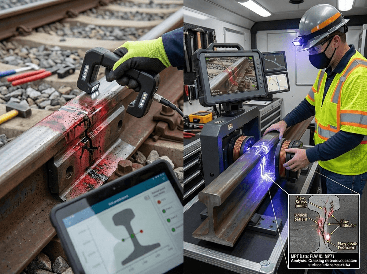
Magnetic particle testing (MT, also called MPT or MPI) finds surface and slightly subsurface cracks in ferromagnetic steel by magnetizing the part and applying iron particles. Every area is magnetized in two directions about 90° apart, and general-industry work follows ASTM E3024/E3024M-22a, while E1444/E1444M-26 applies to aerospace only.
This page is a technique reference: which magnetizing method makes which field, what each current type means for depth, how the field is proved, what the viewing light must be, when to demagnetize, and which standard governs which industry. For MT on rail components and structural welds, see our magnetic particle examination guide for rail and structural steel.
What is magnetic particle testing, and what are MT, MPT and MPI?
Magnetic particle testing magnetizes a ferromagnetic part so that a crack cutting across the field forces flux out of the surface, where the leakage field gathers fine iron particles into a visible line. MT, MPT and MPI all name the same method; there is no technical difference between "testing" and "inspection".
The names vary by publisher, not by technique. ASTM and ISO titles say "magnetic particle testing", ASME Section V calls Article 7 "magnetic particle examination", and ASNT abbreviates the method MT. "MPI" (magnetic particle inspection) is common shop and UK usage.
Use whichever term the contract uses, and write the governing document next to it.
The method works only where the steel can be magnetized. ASTM E3024/E3024M-22a states that MT "is not applicable to non-ferromagnetic metals and alloys such as austenitic stainless steels". Carbon and low-alloy steels, most cast irons and the martensitic and ferritic stainless grades can be tested; austenitic stainless, aluminum, copper alloys, titanium and austenitic manganese steel cannot.
ISO 9934-1:2016 describes the depth limit plainly: MT is "primarily applicable to the detection of surface-breaking discontinuities, particularly cracks", and its sensitivity to discontinuities just below the surface "diminishes rapidly with depth".
Key takeaway: MT, MPT and MPI are one method, and it works only on ferromagnetic material and only near the surface.
Which magnetization method makes which field direction?
A yoke and an encircling coil make a longitudinal field; prods, a head shot and a central conductor make a circular field. MT finds a crack best when the crack lies at about 90° to the field, so each technique finds a different crack orientation.
| Technique | How it magnetizes | Field direction | Cracks it shows best | Typical industries |
|---|---|---|---|---|
| Electromagnetic yoke (AC, DC or AC/DC) | Flux passes from one pole through the part to the other pole | Longitudinal, pole to pole | Cracks running across the line between the poles | Field welds, structural steel, castings, maintenance |
| Permanent-magnet yoke | Same path as an electromagnetic yoke, with no power | Longitudinal, pole to pole | As above | Locations where power isn't available |
| Prods | Current passes through the part between two hand-held contacts | Circular, around the current path | Cracks running parallel to the line between the prods | Heavy welds and large castings |
| Encircling coil or cable wrap | The part sits inside a current-carrying coil | Longitudinal, along the part axis | Transverse cracks, parallel to the plane of the coil | Shafts, axles, bars, bolts |
| Head shot (direct contact) | Current passes end to end through the part, clamped between heads | Circular, around the part axis | Longitudinal (axial) cracks, parallel to the current | Forgings, shafts and machined parts on a wet bench |
| Central conductor | Current passes through a bar threaded through a hollow part | Circular, in the wall around the bore | Axial cracks on the inside and outside surfaces | Tubes, rings, bearing races, gears, pipe couplings |
Sulzer's public MT procedure (TP-0002, Rev. 13, 2024), written to ASME Section V, Article 7, states the same rules in one place. A yoke finds defects "perpendicular to the connecting line between the poles", a coil those "parallel to the plane of the coil", and a central conductor those "parallel to the flow of the current".
The field direction decides the second shot. A shaft magnetized only in a coil will show transverse fatigue cracks but miss an axial seam, so the procedure pairs a coil shot with a head shot or central conductor. Sulzer's procedure requires two magnetizations "as far as possible" at 90°, and never closer than 50° or wider than 130°.
The two shots don't have to come from one machine. Shop benches often combine a coil with a head shot, while a field crew turns a yoke through 90° between placements. Multidirectional benches with three-phase full-wave current switch between circuits so quickly that both fields act during one particle application.
Key takeaway: pick the technique by the crack orientation you need to find, then add a second technique or placement at about 90°.
How much current does each magnetizing technique need?
Current-flow techniques are set in amperes per inch: about 300 to 800 A per inch of diameter for a head shot or central conductor, and about 90 to 125 A per inch of spacing for prods. Coils are set in ampere-turns from the part's length-to-diameter ratio. These ASME-based figures come from public procedures and study guides, so check them against the edition your contract names.
| Technique | Rule of thumb (ASME-based procedures) | Notes |
|---|---|---|
| Head shot or central conductor | 300 to 800 A per inch (12 to 31 A/mm) of outer diameter | For non-round parts use the greatest diagonal; if the current can't be reached, use the maximum available and prove the field (Sulzer TP-0002) |
| Prods, sections 3/4 in. (19 mm) or thicker | 100 to 125 A per inch of prod spacing | Sulzer: 40 to 50 A/cm; spacing over about 3 in. (75 mm) and not more than about 8 in. (200 mm) |
| Prods, sections under 3/4 in. | 90 to 110 A per inch of prod spacing | Sulzer: 36 to 44 A/cm |
| Coil, L/D of 4 or more | Ampere-turns = 35,000 ÷ (L/D + 2), within 10% | L is part length, D its diameter |
| Coil, L/D from 2 up to 4 | Ampere-turns = 45,000 ÷ (L/D) | Below L/D = 2 the coil technique can't be used without extending the part |
| Coil, field beyond 9 in. (225 mm) either side of the coil center | Field adequacy must be shown with a pie gauge or shims | Long parts are shot in sections |
The coil formulas above are the simplified ASME form reproduced in Sulzer's procedure. ASTM E709 and the ASTM practices use separate formulas for low and high fill-factor coils, so a procedure written to ASTM may give a different current for the same part. Fill factor is the ratio of the part's cross-section to the coil's: Sulzer calls 0.5 or more "high" and 0.1 or less "low".
Two quick checks show the scale. A 4 in. (102 mm) diameter shaft on a head shot needs 4 × 300 = 1,200 A to 4 × 800 = 3,200 A. Prods set 6 in. apart on a 1 in. plate need 6 × 100 = 600 A to 6 × 125 = 750 A.
Prods carry an arc-strike risk at every contact. Colorado DOT's bridge procedure (QAP 5930, 2018) says prods are "virtually never used" on its work for that reason, and Sulzer's procedure requires any prod arc strike to be ground out and re-examined.
Key takeaway: current is set per inch of diameter or spacing, or in ampere-turns from L/D, and every formula needs field proof where geometry departs from the simple case.
AC, HWDC or FWDC: how deep does each current reach?
AC concentrates the field at the surface and gives the best sensitivity to surface-open cracks, while half-wave (HWDC) and full-wave rectified DC (FWDC) push the field deeper and can show slightly subsurface flaws. None of them turns MT into a volumetric method.
| Current | Field depth | Particle mobility | Best use | Watch for |
|---|---|---|---|---|
| AC | Shallow: the skin effect confines the field near the surface | Good; the alternating field "shakes" particles toward leakage sites | Fatigue cracks, weld-toe cracks, grinding cracks, in-service inspection | Little reach below the surface; the Ketos ring isn't used with AC |
| HWDC (half-wave rectified) | Deeper than AC | Good; the pulsing field helps dry powder move | Dry powder with prods or yokes on welds and castings where near-surface flaws matter | Higher residual magnetism than AC |
| FWDC, single or three phase | Deeper than AC | Lower than AC or HWDC | Wet benches, coils and central conductors; three-phase FWDC drives multidirectional units | Strong residual fields; DC demagnetization usually needed |
| Capacitor discharge or pulsed DC | Short, high-current shots | Used mainly with the residual technique | Large or retentive parts, often on a central conductor | Residual technique is less sensitive than continuous |
The advantages table in Sulzer's procedure, taken from the ASME tutorial material, says prods used "in conjunction with half-wave rectified alternating current and dry powder" provide "excellent sensitivity to subsurface discontinuities as well as surface type". The same table credits a central conductor with HWDC and dry powder for near-surface flaws.
The AC limit is real in the field. Colorado DOT's continuous AC yoke procedure with dry visible powder says subsurface discontinuities "can not be reliably detected, e.g. cracks greater than 1/64 inch from the surface". Sulzer's procedure prefers AC "for the detection of discontinuities, such as fatigue cracks, that are open to the surface".
Worked example: how thin is the AC skin?
The standard depth of penetration for an alternating field is δ = 503 × √(ρ ÷ (μr × f)), with δ in meters, ρ the resistivity in Ω·m, μr the relative permeability and f the frequency in Hz (Evident eddy current tutorial). Take a carbon steel with an assumed ρ = 2.0 × 10⁻⁷ Ω·m and μr = 500, at 60 Hz.
- ρ ÷ (μr × f) = 2.0 × 10⁻⁷ ÷ (500 × 60) = 6.67 × 10⁻¹²
- √(6.67 × 10⁻¹²) = 2.58 × 10⁻⁶
- δ = 503 × 2.58 × 10⁻⁶ = 1.30 × 10⁻³ m, about 1.3 mm (0.05 in.)
With μr = 100 the same arithmetic gives 503 × √(3.33 × 10⁻¹¹) = 2.9 mm. Permeability changes with steel grade and with how hard the part is magnetized, so treat these as orders of magnitude, not a detection depth. The point stands: an AC field lives in roughly the outer millimeter or few, and DC is the tool when the target sits deeper.
Worked example: what the Ketos ring shows about DC
The tool steel (Ketos) ring is a standard check of DC and rectified equipment. Magnaflux's data sheet for its AS 5282 ring lists 12 holes at depths increasing by 0.07 in. (1.78 mm), from 0.07 in. for hole 1 to 0.84 in. (21.34 mm) for hole 12, and states the ring "is not intended for use with AC magnetic fields".
At 1,000 A FWDC or HWDC on a central conductor, the same sheet asks for at least 5 holes with wet fluorescent particles and 6 with dry powder. Hole 5 sits at 5 × 0.07 = 0.35 in. (8.89 mm) and hole 6 at 6 × 0.07 = 0.42 in. (10.67 mm). At 2,500 A the minimums rise to 7 (wet fluorescent) and 8 (dry powder), or 0.49 in. and 0.56 in.
Those depths are for drilled holes in an annealed tool-steel ring with a central conductor, an ideal case. They show that DC fields reach deep and that dry powder does better than wet particles on subsurface leakage. They don't mean MT will find a 0.35 in. deep flaw in a weld.
Key takeaway: AC for surface-open cracks, HWDC with dry powder for near-surface flaws in welds and castings, FWDC for wet benches, and UT whenever the flaw could be deeper than a few hundredths of an inch.
How is the magnetic field verified?
The field is verified three ways: a lift test proves a yoke's strength, a pie gauge or artificial flaw shims prove the field is present and correctly oriented on the part, and a Hall-effect gaussmeter measures the tangential field strength. Each tool answers a different question, and procedures differ on which one is mandatory.
| Tool | What it proves | Where it fits | Limits |
|---|---|---|---|
| Yoke lift test (steel test weight) | The yoke's lifting power at the pole spacing to be used | Yokes only, before use and at the frequency the procedure sets | Says nothing about the field on a thick or curved part |
| Pie gauge (ASME field indicator) | A field exists and its direction, by a line of particles across the copper face | Best with dry powder (Sulzer); placed on the part during magnetization | Sulzer treats it as direction proof only; Magnaflux markets it for "strength and direction" |
| Artificial flaw shims (QQI or Castrol-type strips) | The particle system can show a known notch under the actual field | Best with wet particles (Sulzer); required for multidirectional fields | A shim must sit flat and tight on the surface |
| Hall-effect gaussmeter, tangential probe | The tangential field strength at the surface, in gauss or kA/m | Single-direction fields from yokes, prods, head shots and central conductors | Not for encircling coils or multidirectional fields under ASME-based procedures (Sulzer) |
| Ketos ring | DC and rectified bench performance over time | Wet benches with a central conductor | Not for AC |
Sulzer's procedure requires a tangential field of at least 2.4 kA/m (30 Oe), "but not so strong that it causes the masking of relevant indications", and treats the pie gauge and shims as proof of "the presence and the direction of the magnetization only". The vendor wording differs: Magnaflux's ASME field indicator sheet says a suitable field is shown "when a clearly defined line of particles form across the copper face", and tells the user to change technique or raise the current if no line forms.
The yoke lift values depend on the document, which is why vendors appear to disagree. The figures below come from the EMA knowledge base and public secondary sources; name the governing document beside any lift value you use.
| Document | AC yoke | DC yoke | Confidence |
|---|---|---|---|
| ASME Section V, Article 7 (T-762) | At least 10 lb (4.5 kg) at maximum pole spacing | At least 40 lb (18 kg) at maximum pole spacing | Med, from study guides and a Sulzer procedure; CONFIRM in the 2025 edition |
| AWS D1.1:2025 (study guide summary) | At least 10 lb (4.5 kg) | 40 lb (18 kg), or 30 lb (14 kg) at 2 to 4 in. spacing | Low-Med; CONFIRM |
| AWS D1.5 (bridge code, public copies) | 10 lb (45 N) at 2 to 4 in. | 30 lb (135 N) at 2 to 4 in.; 50 lb (225 N) at 4 to 6 in. | Low-Med; CONFIRM |
| ASTM E709-21 | Has its own lifting-power check | Vendor tables disagree on the DC figure | Low; CONFIRM |
| ASTM E1444/E1444M-26 | n/a: "portable battery powered electromagnetic yokes are outside the scope" | High (store scope) |
A gaussmeter reading also needs care. Magnaflux's field indicator sheet warns that readings "relate only to the magnitude of external leakage fields and should not be misconstrued as the flux density within the part".
Key takeaway: lift test for the yoke, pie gauge or shims for direction and particle response on the part, gaussmeter for strength, and the document named beside every number.
Wet or dry, visible or fluorescent: which particles should you use?
Wet fluorescent particles give the highest sensitivity to fine surface cracks on smooth parts, while dry visible powder suits rough, hot or outdoor surfaces and, with HWDC, near-surface flaws. Wet visible particles sit between the two.
| Particle system | Carrier and viewing | Strengths | Limits | Typical setting |
|---|---|---|---|---|
| Wet fluorescent | Oil or water bath; UV-A in a darkened area | Finest surface cracks; the only method E1444 covers for aerospace | Needs darkness, a UV-A lamp, bath concentration and contamination checks | Shop benches: aerospace, forgings, axles, machined parts |
| Wet visible (black or red) | Aerosol or bath; white light, often over white contrast paint | Good sensitivity without a dark booth | Less sensitive than fluorescent | Field welds, pressure equipment, maintenance |
| Dry visible powder (gray, red, yellow) | Air-applied powder; white light | Rough as-welded or cast surfaces; best response to subsurface leakage with HWDC | Least sensitive to very fine cracks; wind and moisture disturb it | Structural welds, castings, outdoor work |
| Dry fluorescent | Powder; UV-A | Hot or rough surfaces where fluorescence helps | Less common; same darkness needs as wet fluorescent | Special applications |
ASTM E709-21 lists the techniques it covers as dry powder (8.4), wet suspensions (8.5), magnetic slurry or paint (8.5.7) and polymer dispersions (8.5.8). Temperature limits come from the particle maker: Sulzer's procedure notes wet particles are "normally" limited to about 50 °C (122 °F).
Freight-rail research gives one measured comparison. TTCI's Technology Digest TD-09-009 (Carter, 2009) found on car castings that "the wet fluorescent method was the most dependable method for finding finer surface indications", ahead of dry MT and liquid penetrant.
Key takeaway: wet fluorescent in the shop for the finest cracks, dry powder in the field and for near-surface work, and the particle maker's temperature limit observed.
What UV-A and white-light levels does magnetic particle testing require?
Fluorescent MT is generally done with at least 1,000 µW/cm² of UV-A at the examination surface and no more than about 2 fc (20 lx) of ambient white light, and visible MT with about 100 fc (1,000 lx) of white light at the surface. These are the figures most documents use, but each document states its own, and the ASTM and ASME texts are paywalled.
| Item | ASME V, Article 7 | ASTM E1444 (aerospace) | ASTM E3024 and E709 | Other references |
|---|---|---|---|---|
| UV-A at the examination surface | ≥1,000 µW/cm² (Med, study guides and Sulzer T-777.2 citation) | ≥1,000 µW/cm² (10 W/m²) (Med, secondary copies) | Not confirmed from public pages (CONFIRM) | ISO 3059 sets a maximum of 5,000 µW/cm² at the surface (Magnaflux, vendor) |
| Ambient white light, fluorescent viewing | ≤2 fc (about 20 lx) (Med) | ≤2 fc (20 lx) (Med) | CONFIRM | Sulzer ≤21.5 lx |
| White light, visible particles | ≥100 fc (about 1,000 lx) (Med) | 100 fc (1,076 lx) (Med) | CONFIRM | Sulzer ≥1,076 lx; Colorado DOT QAP 5930 (D1.5 bridge work) 32.5 fc |
| Dark adaptation before viewing | ≥5 min (Med) | Stated in the practice (CONFIRM value) | CONFIRM | Sulzer 5 min |
| Lamp warm-up | n/a | n/a | n/a | Sulzer: 10 min for non-LED lamps |
The 1,000 µW/cm² figure is measured at the part, not at a fixed lamp distance. Some procedures check lamps at 15 in. (38 cm) for convenience, and a D1.1 study guide words the requirement that way, so check which one your procedure means. Magnaflux notes that many lamps are built to give about 5,000 µW/cm² at 15 in., well above the minimum.
Ambient light is the figure most often missed in the field. A booth with an open door, or a tent in daylight, can exceed 2 fc at the part even when it looks dark. Measure at the examination surface with a calibrated meter, and don't carry one document's figure into another document's job.
Key takeaway: measure UV-A, ambient light and white light at the part, and record the document that set each limit.
When must parts be demagnetized, and to what residual field?
Demagnetize when residual magnetism could affect later machining, welding, bearings, instruments or service, or when the procedure or customer requires it; a common limit is 3 gauss (0.24 kA/m). Section V's Article 7 is a method article, so the residual limit normally comes from the referencing code, the customer or the written procedure.
Sulzer's procedure exempts structural fabrications, castings and pipework and otherwise requires the residual field to be at most "0.24 kA/m (3 Oe) unless otherwise agreed in writing". Aerospace and customer specifications often use a similar 3 G figure; confirm it in the document you work to.
Demagnetizing works by applying a field at least as strong as the magnetizing field, in nearly the same direction, then reversing it while reducing it to zero. Sulzer lists four methods: withdrawal from an AC coil, decreasing AC, demagnetizing with a yoke, and reversing DC.
| Magnetizing current | Usual demagnetizing approach | Why |
|---|---|---|
| AC (yoke or coil) | AC coil withdrawal or decreasing AC | AC residual fields are shallow |
| HWDC or FWDC | Reversing, step-down DC | An AC demagnetizer can't reach a field that DC drove deep into the section |
| Circular field (head shot, central conductor) | Convert to a longitudinal field, then demagnetize | In common practice a circular residual field stays inside the part and barely registers on a field indicator, so it is converted first (CONFIRM in your procedure) |
A short check shows the workflow. A shaft magnetized with FWDC in a coil reads 7 G at its end on a calibrated field indicator, against a 3 G limit. It goes back through reversing step-down DC, reads 1.5 G, and passes; the reading and the indicator's serial number go in the report.
Readings depend on the meter. Magnaflux's 10 G calibrated indicator is accurate to ±0.5 G and its 20 G model to ±1.0 G, so a 3 G limit read on the coarser scale has little margin.
Key takeaway: demagnetize when the next operation or the customer needs it, use reversing DC after DC work, and measure the residual field where flux leaves the part.
Which magnetic particle testing standard applies to which industry?
General industry uses ASTM E3024/E3024M-22a with E709 as the tutorial, aerospace uses E1444/E1444M-26, ASME work uses Section V Article 7, international work uses the ISO 9934 series, and structural welds are accepted to AWS D1.1 or D1.5. Technique documents say how to test; acceptance always comes from somewhere else.
ASTM E709-21 puts the split in one sentence:
"This guide does not indicate, suggest, or specify acceptance standards for parts/pieces examined by these techniques." (ASTM E709-21, section 1.3)
| Document | What it is | Acceptance criteria? | Use it for |
|---|---|---|---|
| ASTM E3024/E3024M-22a, Magnetic Particle Testing for General Industry | Minimum requirements for industrial MT; "Refer to Practice E1444/E1444M for aerospace applications" | No | Industrial specifications: forgings, castings, machinery, welds, in-service parts |
| ASTM E1444/E1444M-26, Magnetic Particle Testing for Aerospace | Wet fluorescent aerospace practice; replaces MIL-STD-1949; battery yokes out of scope | No | Aerospace only. A non-aerospace spec that cites E1444 probably predates E3024 |
| ASTM E709-21, Standard Guide for Magnetic Particle Testing | A guide covering dry and wet techniques; explicit requirements go in a written procedure | No (1.3) | Writing and reviewing procedures; referenced by AWS D1.1 |
| ASME BPVC Section V, Article 7 (2025 edition) | MT methods for examinations other ASME sections require | No; from the construction code (Section VIII, B31.3) | Boilers, pressure vessels, piping |
| ISO 9934-1:2016, general principles; ISO 9934-2:2015, detection media; ISO 9934-3:2015, equipment | International MT method series; Part 1 "does not apply to the residual magnetization method" | No ("Acceptance criteria are not defined") | International and European specifications |
| ISO 17638:2016, MT of welds, with ISO 23278:2015 acceptance levels | Weld technique plus a separate acceptance standard | ISO 23278 sets acceptance levels | Welds to ISO-based contracts |
| ISO 3059:2012, viewing conditions | Illuminance and UV-A requirements for MT and PT | n/a | Lighting checks on ISO jobs |
| AWS D1.1/D1.1M:2025-AMD1, Structural Welding Code – Steel | MT in Clause 8 (8.10 per study guides), technique per E709 | Yes: MT indications judged against the visual criteria of Table 8.1 (study guide; CONFIRM) | Buildings and general structures, when the contract calls for MT |
| AWS D1.5 (AASHTO/AWS), Bridge Welding Code | Bridge code with its own MT provisions and yoke lift table | Yes | Highway and AREMA-designed railroad bridges |
Study guides for D1.1:2025 describe a linear indication as one whose length "exceeds three times its width" and give cracks "zero tolerance"; confirm both against the code before using them for disposition. For the static and cyclic limits that follow, see our AWS D1.1 weld inspection criteria.
Personnel qualification is separate again. In the US, MT technicians are usually certified by their employer to a written practice under SNT-TC-1A or CP-189; see our SNT-TC-1A certification guide.
Key takeaway: E3024 for industry, E1444 for aerospace only, ASME V Article 7 for ASME work, ISO 9934 internationally, and the construction code or AWS D1.1/D1.5 for acceptance.
Worked example: magnetizing a 36 in. shaft in two directions
This example sets up wet fluorescent MT of a 36 in. (914 mm) long, 4 in. (102 mm) diameter steel shaft on a bench, using a coil for transverse cracks and a head shot for axial cracks. It uses the ASME-based formulas from Sulzer's procedure; a procedure written to ASTM E3024 would set the coil current with its own fill-factor formula.
Inputs
| Item | Value |
|---|---|
| Part | Carbon steel shaft, L = 36 in., D = 4 in., L/D = 36 ÷ 4 = 9 |
| Particles | Wet fluorescent, continuous technique |
| Coil | 5-turn bench coil |
| Current | FWDC for both shots |
| Residual limit | 3 G (0.24 kA/m) after test |
Step 1: longitudinal shot (coil). L/D = 9 is at least 4, so ampere-turns = 35,000 ÷ (9 + 2) = 35,000 ÷ 11 = 3,182. With 5 turns, I = 3,182 ÷ 5 = 636 A, within 10%: 573 A to 700 A.
Step 2: coil coverage. The field is taken as effective 9 in. either side of the coil center, or 18 in. per position. The shaft is 36 in. long, so two positions would cover it with no overlap. Use three positions, centered at 8, 18 and 28 in., covering −1 to 17 in., 9 to 27 in. and 19 to 37 in. Each pair overlaps by 8 in., and both ends are covered.
Step 3: circular shot (head shot). At 300 to 800 A per inch of diameter, the range is 4 × 300 = 1,200 A to 4 × 800 = 3,200 A. Set 2,000 A (500 A per inch), well inside the range and within the bench's rating.
Step 4: prove the fields. Place a shim on the shaft surface for each shot: notch across the axis for the coil shot, notch along the axis for the head shot. Check that each shim's notch shows under its own field, since Sulzer's procedure bars Hall-effect readings with encircling coils.
Step 5: viewing. Measure UV-A at the shaft surface (at least 1,000 µW/cm²), ambient light (at most 2 fc) and allow 5 minutes of dark adaptation before reading.
Step 6: demagnetize. After FWDC the shaft reads 7 G at one end, over the 3 G limit. Reversing step-down DC brings it to 1.5 G, which passes.
Result: 3 coil shots at about 636 A, 1 head shot at 2,000 A, two shims, a light check and a demagnetization check give a two-direction examination of the full shaft surface. Any relevant indication still needs a disposition against the customer's acceptance standard.
What can't magnetic particle testing do?
MT can't find internal flaws, can't test non-magnetic materials, can't size crack depth, and misses cracks that lie parallel to the field. Each limit has a practical cause.
- Depth: AC reaches only the outer millimeter or so, and even DC misses anything well inside the section. Lack of fusion inside a weld, an internal void in an axle or a transverse defect inside a rail head needs UT or RT.
- Material: austenitic stainless steel, aluminum, copper alloys, titanium and austenitic manganese steel can't be magnetized. Welds made with austenitic filler on carbon steel are a common trap: the weld itself isn't magnetic.
- Orientation: a crack parallel to the field makes little leakage, which is why two directions about 90° apart are required.
- Sizing: MT shows surface length and location, not depth. Depth comes from grinding and re-examining, or from UT.
- Non-relevant indications: weld toes, undercut, section changes, permeability boundaries and over-magnetization all hold particles without a crack.
- Surface condition: thick paint, scale, oil and rough as-welded ripples hide fine cracks; thin nonmagnetic coatings need a demonstration.
- Coverage: about 1 in. (25 mm) near each yoke pole isn't evaluated, and coils lose field toward the ends of long parts.
- Residual magnetism: DC leaves fields that can disturb later welding or machining, so demagnetization has to be planned.
For a side-by-side view of what each method covers, see our comparison of non-destructive testing methods. Visual inspection should come first in any MT job; see visual testing (VT). For rail, where UT carries the internal search, see ultrasonic testing vs magnetic particle testing in rail.
How EMA Industries applies this
EMA Industries performs magnetic particle testing as part of its AWS D1.1 structural weld inspection services, alongside UT and PT. Based in Southern California and mobilizing nationwide, EMA also offers NDT Level III services, which can include writing or reviewing MT procedures so they name the governing document, the field directions, the lift-test value and the lighting limits. See our ultrasonic and weld examination services or contact EMA Industries to scope MT for your welds or components.
Frequently asked questions
What is the difference between MT, MPT and MPI?
There is none in technique. MT is the ASNT abbreviation, ASTM and ISO titles say "magnetic particle testing", ASME Section V says "magnetic particle examination", and MPI is common shop usage. Use the contract's term and name the governing document.
How deep can magnetic particle testing find flaws?
MT is a surface method with limited near-surface reach. A Colorado DOT AC yoke procedure says cracks more than about 1/64 in. below the surface can't be reliably detected, while DC and HWDC reach deeper. Flaws well inside the section need UT or RT.
Should I specify ASTM E1444 or E3024?
Specify E3024/E3024M-22a for general industry, welds and machinery, and E1444/E1444M-26 only for aerospace. E1444 is now scoped to aerospace with the wet fluorescent method and excludes battery-powered yokes, so older industrial specifications that cite it should be updated.
Do pie gauges and shims measure field strength?
Not reliably. Sulzer's ASME-based procedure treats them as proof of field presence and direction only and requires a calibrated gaussmeter for strength. Shims also show whether the particle system can reveal a known notch, which a gaussmeter can't.
When is demagnetization required?
When residual magnetism would affect later machining, welding, bearings, instruments or service, or when the customer or procedure requires it. A common limit is 3 G (0.24 kA/m); after DC magnetization, use reversing step-down DC and measure the residual field before release.
Sources
Standards (publisher and catalog pages)
- ASTM E3024/E3024M-22a, Standard Practice for Magnetic Particle Testing for General Industry, store page (Active): scope 1.1–1.3
- ASTM E1444/E1444M-26, Standard Practice for Magnetic Particle Testing for Aerospace, store page (Active, May 22, 2026): scope 1.1–1.4, including the battery-yoke exclusion
- ASTM E709-21, Standard Guide for Magnetic Particle Testing, store page (Active): scope 1.1–1.4 and the section 1.3 quotation
- ASME BPVC Section V, Nondestructive Examination, product page
- AWS D1.1/D1.1M:2025-AMD1, Structural Welding Code – Steel, product page
- EN ISO 9934-1:2016, EN ISO 9934-2:2015 and EN ISO 9934-3:2015, catalog scopes (Published)
- EN ISO 17638:2016, EN ISO 23278:2015 and ISO 3059:2012, catalog scopes (Published)
Procedures and technical data
- Sulzer TP-0002, Magnetic particle testing of ferromagnetic materials, Rev. 13, July 10, 2024 (ASME V-based company procedure): field directions, current rules, coil formulas, field verification, lighting, demagnetization
- Colorado DOT QAP 5930, Magnetic Particle Inspection Procedure; Continuous Yoke, Dry, Visible Particles, Sept 12, 2018
- Magnaflux Tool Steel Ring product data sheet, June 2018 (vendor)
- Magnaflux Hall Effect Gaussmeter product data sheet, June 2018 (vendor)
- Magnaflux Magnetic Field Indicators product data sheet, March 2015 (vendor)
- Magnaflux ASME Field Indicator product data sheet, August 2022 (vendor)
- Magnaflux, "UV-A Intensity" (vendor blog): ISO 3059 maximum and lamp benchmark
- Evident, Depth of Penetration (eddy current tutorial): standard depth of penetration
- TTCI TD-09-009, Inspection Methods for Side Frame, Bolster, and Knuckle Castings, D. Carter, March 2009
- open-exam-prep, AWS D1.1 MT, PT and inspection records study guide (study guide, Med): D1.1:2025 clause, lift and acceptance summaries