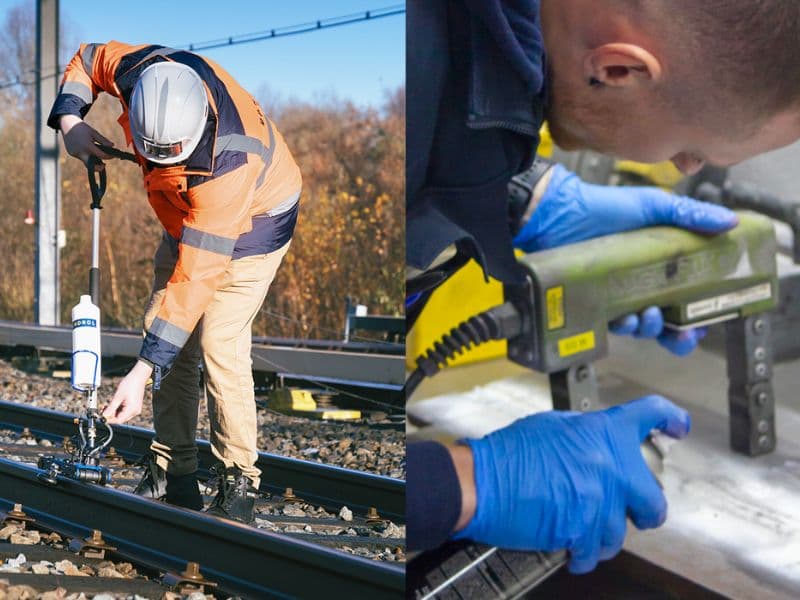
Ultrasonic testing vs magnetic particle testing in rail is a choice between depth and surface. Ultrasonic testing (UT) sends sound through the full 7-5/16 in. height of 136RE rail to find the internal flaws 49 CFR 213.237 targets. Magnetic particle testing (MT) finds cracks at, or within about 1/64 in. of, a ferromagnetic surface.
That one difference decides most rail jobs. A transverse fissure inside the head, a bolt hole crack behind a joint bar or slag in a thermite weld base can only be found by UT. A toe crack on a ground weld, a crack at a switch point tip or a crack someone has already seen is often confirmed faster and more cheaply by MT.
This page compares the two by rail feature, with depth limits, sensitivity, surface preparation, speed and the jobs that need both. For choosing among all NDT methods on a railway, see EMA's ultrasonic testing vs other NDT methods guide; for the physics of every method across industries, see the comparison of non-destructive testing methods.
Contents: Feature by feature · Depth · Sensitivity · Head, web and base · Welds · Turnouts and components · Surface prep · Speed · Worked example · Using both · Standards · Limits · FAQ
Ultrasonic testing vs magnetic particle testing: which fits which rail feature?
Use UT wherever a defect can grow inside the steel or behind something, and MT where the crack breaks a ferromagnetic surface you can reach and clean. The table maps the common rail features and defects to the method that fits.
| Rail feature or defect | Where it starts | UT | MT | Better choice |
|---|---|---|---|---|
| Transverse fissure, compound fissure | Inside the head | Yes: 70° shear wave | No | UT |
| Detail fracture | At or near the head surface, then grows across the head | Yes: 70° shear wave | Shows surface head checks or shelling only, not the fracture | UT |
| Horizontal split head | Inside the head, about 1/4 in. or more below the running surface | Yes: 0° beam | Only once it reaches the side of the head | UT |
| Vertical split head, head-web separation | Inside the head or at the head-web fillet | Yes: angle and side-looking beams; 0° shows loss of bottom | Only to confirm a crack already visible at the fillet | UT |
| Split web, piped rail | Inside or along the web | Yes | Only where it is open on the web face | UT |
| Bolt hole crack | Edge of the hole, behind the joint bars | Yes, with the bars in place | No, while the bars are on | UT |
| Broken base, base cracks | Base edges and underside | Hand UT; vehicle UT covers only the base under the web | Base top and edges between ties | Both, by location |
| Head checks, gauge corner RCF | Running surface | Poor: surface noise is gated out | Shows surface cracks locally; not a track method | Neither: eddy current and visual |
| Thermite weld | Web, web-base fillet and base for most failures | Yes: hand UT of head, web and base | Ground head and accessible surfaces | UT, with MT on the surface |
| Flash-butt weld | Bond line (planar) | Yes | Trimmed upset only | UT |
| Switch point | Tip and top surface | Limited near the thin tip | Yes: rail steel | MT, plus UT on the thicker section |
| Cast manganese frog | Nose, point, casting ends | Poor: coarse grain | No: essentially non-magnetic | Neither: visual and penetrant |
| Joint bars | Top center of the bar | Research only | Yes, on removed bars | MT on removed bars |
| Slot or head repair weld | Repair cavity and weld | Maps the defect before repair, checks the weld after | Checks the ground cavity before welding | Both |
The defect definitions come from 49 CFR 213.113(d). For example, a detail fracture is "a progressive fracture originating at or near the surface of the rail head", which is why the surface damage it starts from can be visible while the fracture itself is not.
Key takeaway: if the flaw can be inside the steel, the answer is UT; MT only answers for the surface.
How deep can UT and MT see into rail steel?
UT sees through the whole rail section, from the running surface to the base, while MT sees surface-breaking cracks and, with AC, little more than 1/64 in. (0.4 mm) below the surface. That gap is why they are not substitutes.
| Method and setup | Depth it reaches in rail | Source or basis |
|---|---|---|
| UT, 0° longitudinal beam | Full rail height: about 7-5/16 in. (186 mm) on 136RE, with a base echo near 63 µs | Calculated from section height and steel velocity |
| UT, 70° shear beam | The rail head; a sound path of 2.92 in. reaches 1 in. deep | 1 ÷ cos 70° = 2.92 |
| UT from a test vehicle | Head, web and the base directly under the web | 2014 FRA final rule preamble |
| UT, hand probes on the base | Base flanges, using skip paths and angle probes | TTCI TD21-027 (2021) |
| MT, AC yoke, dry visible powder | Surface-open cracks; subsurface flaws below about 1/64 in. not reliably found | Colorado DOT QAP 5930 (2018) |
| MT, DC or half-wave DC | Somewhat deeper than AC; no reliable published depth figure | Practice; guides disagree |
FRA described in-track coverage in its 2014 rail integrity rule:
"Transducers normally scan the entire rail head and web, as well as the portion of the base directly beneath the web." — FRA, Track Safety Standards; Improving Rail Integrity, 79 FR 4234 (January 24, 2014)
On the MT side, the Colorado DOT's yoke procedure, written to ASTM E709 and AWS D1.5, says MT "shall be applied to detect discontinuities that are open to the surface" and that subsurface discontinuities "can not be reliably detected, e.g. cracks greater than 1/64 inch from the surface" (QAP 5930). ASTM's general-industry practice, E3024/E3024M-22a, describes MT as a method for "surface or slightly subsurface discontinuities in ferromagnetic material".
UT has its own near-surface weakness, and in rail it is not the classic contact-probe dead zone (see EMA's dead zone article). FRA's 2011 rolling contact fatigue review notes that UT analysis ignores the first few millimeters of the head because the surface returns noise there (DOT/FRA/ORD-11/24). That shallow band is where MT and eddy current work.
Key takeaway: UT covers inches of steel and MT covers a fraction of a millimeter; the overlap is a thin layer at the surface.
Which method is more sensitive, and to which cracks?
UT is sensitive to cracks facing the beam and MT to cracks crossing the magnetic field. Neither has one sensitivity figure that holds across rail, welds and operators.
UT. The probe angle is chosen by the crack plane. A transverse fissure lies "substantially at a right angle to the length of the rail" (213.113(d)), so a 70° shear wave aimed along the rail catches it; a horizontal split head lies flat, so the 0° beam does. A crack parallel to the beam gives little echo, which is why test systems combine 0°, 37–45° and 70° channels plus side-looking probes.
Published rail UT figures always carry conditions:
- A TTCI review of conventional test vehicles put detection at "about 90 percent" of flaws, with about 10% going undetected during periodic inspection (TD-16-030, 2016).
- In a TTCI study, transverse defects under shells were detected 62% of the time against 77% where the surface had no anomaly; the shelled sample was only 7 defects, against 33 (TD-99-006).
- FRA's 2026 study of handheld rail UT, based on 512 simulated responses, gave a mean POD of 95.8% for a flaw of 25% head area at one detection threshold, falling as the threshold was raised (DOT/FRA/ORD-26/07).
MT. MT shows a crack only when the field crosses it. Sulzer's ASME V-based procedure (TP-0002, Rev. 13, 2024) gives the yoke's detectable defect orientation as "perpendicular to the connecting line between the poles", and requires two magnetizations about 90° apart (Sulzer TP-0002). Particle choice matters too: on freight car castings, TTCI found "the wet fluorescent method was the most dependable method for finding finer surface indications", ahead of dry MT and penetrant (TD-09-009, 2009).
No published probability-of-detection study for MT on rail or rail welds was found (search, October 2026). The nearest railroad study covers tank car welds, not rail (DOT/FRA/ORD-16/35, 2016).
Key takeaway: compare sensitivity only for a stated crack, orientation and setup; a "UT finds more" or "MT is more sensitive" claim without them means nothing.
Which method should inspect the rail head, web and base?
UT is the method for the head and web in track, and the base needs hand UT plus, where it can be reached, a surface method. The details differ by part of the section.
Rail head
Transverse and compound fissures, detail fractures and split heads grow inside the head, so UT finds them and MT can't. 49 CFR 213.237 requires "internal rail inspections" on Class 3 to 5 track at set intervals, and 213.237(f) requires equipment "capable of detecting defects between joint bars, in the area enclosed by joint bars". The rule names no method, but MT can't produce a continuous internal search, so it can't meet either duty.
MT can show surface damage on the head, such as head checks and grinding cracks, which helps in an investigation. A 1973 British Journal of NDT paper by J. Banks described MT and dye penetrant on wheel-burnt rail heads and thermite-welded running faces (TRID abstract). It is not a track inspection method, and for routine head-check work the in-track tool is eddy current. See EMA's eddy current vs ultrasonic testing and head checks articles.
Rail web
UT reads the web with the 0° beam (web thinning and loss of bottom) and angle beams (cracks at the fillets and from bolt holes). MT reaches only cracks that are already open on the web face. 213.113(d) notes that a vertical split head can show "a crack or rust streak" under the head close to the web; MT can confirm such a crack, but by then UT should already have found it.
Rail base
The base is the weak spot of vehicle UT. TTCI's thermite weld survey put it plainly: the "ultrasonic rail flaw detection process only scans the head and web of the rail, and not the majority of the base" (TD-00-013, 2000). Hand UT with angle probes and skip paths can reach the base flanges. MT can check the base top surface and the edges between ties for surface cracks, but the underside sits on the tie plate and can't be reached in track.
Key takeaway: head and web by UT; the base by hand UT, with MT on the surfaces you can reach.
Which method should inspect thermite and flash-butt welds?
Both weld types need UT for the volume, and MT adds a check of the finished surface. In service, a bad weld is a rail defect: 213.113(d)(6) defines a defective weld by discontinuities "exceeding 5 percent of the rail head area individually or 10 percent in the aggregate, oriented in or near the transverse plane", from causes such as lack of fusion, slag or sand, shrinkage cracking or fatigue, starting "in the rail head, web, or base".
Thermite welds
Thermite failures cluster where vehicle UT is weakest. In TTCI's survey of 265 revenue-service failures, slag and porosity caused 40%, with 56% of those at the web-to-base fillet (TD-00-013). A later TTCI digest found that about 95% of thermite breaks at its test track were in the web, web-base fillet and base, and summed up current practice:
"Existing practices for flaw detection and characterization in thermite rail welds after installation are limited to visual inspection, which does not reveal purely internal defects." — TTCI Technology Digest TD-21-027 (Poudel, 2021)
So each new thermite weld needs hand UT of head, web and base. The same digest found that full base coverage "could not be achieved without using a 'full skip'" and that the weld collar line gave poor signal-to-noise. MT then checks the ground running surface and gauge face, and any accessible collar edge, for surface cracks and hot tears. Details are in EMA's aluminothermic weld inspection guide.
Flash-butt welds
Flash-butt welds fail mainly through planar defects at the bond line: lack of fusion, "cold" welds from too little heating before upset, and silicate "matt spots". Those are internal and flat, which is UT work. MT only checks the trimmed upset for surface cracks. See flash-butt weld inspection.
The AWS rail welding specification, D15.2/D15.2M:2022, Specification for Joining Railroad Rail and Related Rail Components, lists visual and ultrasonic acceptance tables (Tables 8.1 and 8.2) in its public preview, and no magnetic particle table (D15.2 preview). Acceptance for rail welds otherwise comes from the owner's specification and the kit or plant procedure; check what your contract names.
Key takeaway: UT accepts or rejects the weld volume; MT is a surface add-on, not a substitute.
What about switch points, frogs, bolt holes and other components?
Turnouts and joints split the methods sharply: MT suits switch points and removed joint bars, UT suits bolt holes in track, and neither suits cast manganese frogs.
Switch points. Switch points are machined rail steel, so MT works well on the tip and top surface, where chipping and cracks from wear and fit-up appear. The thin, tapered tip limits hand UT, while the thicker section behind it can be tested normally. Under 49 CFR 213.135(b), "broken or cracked switch point rails" follow the 213.113 remedial actions, except that action B governs where joint bars can't be placed. Turnout inspection is covered in railroad switch and crossing inspection.
Cast manganese frogs. Most mainline frogs and crossing diamonds are cast austenitic manganese steel. FRA research report RR 22-25 (2022) calls the steel "highly attenuative" and "coarse-grained, nonhomogeneous, and anisotropic", which scatters ultrasound into noise, and records that revenue service examinations "currently use only visual inspections" (RR 22-25). The steel is essentially non-magnetic, and ASTM E3024 excludes non-ferromagnetic alloys, so MT is the wrong tool; penetrant is the surface method. The carbon rail parts of a rail-bound frog can still take UT and MT.
Bolt holes. Bolt hole cracks grow from the hole into the web behind the joint bars. UT finds them with the bars in place, which is what 213.237(f) requires; MT would need the bars off and still couldn't reach inside the hole well. See bolt hole cracks in rail.
Joint bars, bolts and other parts. About 97% of reported joint bar defects are at the top center of the bar. In service, bars are checked by eye; once removed, MT is the practical crack check, and UT of bars in place remains research (0.5 MHz worked best in MxV Rail trials). Bolts are normally replaced rather than tested. See rail joint inspection.
Key takeaway: in a turnout, MT earns its place on switch points and removed parts; UT stays on the rail, welds and bolt holes.
How much surface preparation does each method need?
MT needs a clean, dry, cool surface with only a thin coating, while UT needs a surface that couples sound and is free of loose debris. On rail, both are slowed by grease, scale and weld finish.
| Condition | UT | MT |
|---|---|---|
| Basic requirement | Couplant contact; loose scale, debris and heavy rust removed at the probe path | "Clean, dry, and free from contaminants" (oil, grease, loose rust and scale, thick paint, sand, spatter), per QAP 5930 |
| Paint and coatings | Thin, well-bonded coatings can stay, but they add sound path and loss | Paint up to 2 mils (QAP 5930) or nonmagnetic coatings up to 0.002 in. (0.05 mm, Sulzer); thicker needs a sensitivity demonstration |
| Flange lubricant and grease | Disturbs coupling; FRA notes lubrication and debris as test problems | Must be removed, or particles won't move or will be masked |
| Weld finish | Rough collars and un-ground flashing cause false echoes; grind the running surface | Rough as-welded ripples trap powder and hide fine cracks; grind or use contrast paint |
| Temperature | Wedges and couplants have makers' temperature limits | Wet particles normally limited to about 122 °F (50 °C) by the consumable maker (Sulzer), so wait for a fresh thermite weld to cool |
| Geometry | Needs a flat or contoured contact; the thin switch point tip is hard | Poles must seat; about 1 in. (25 mm) around each pole can't be evaluated |
A thermite weld is the common case where both struggle. The DoD guide specification for thermite rail welds says "No finishing is required on the web and base of rail" (UFGS 34 11 19.00 20), so the collar stays there, which breaks contact for UT probes and holds particles for MT. Plan to test the web and base from beside the collar, with angled paths for UT.
Key takeaway: budget preparation time for both methods; on rail welds it often exceeds the test itself.
How fast is each method, and which can cover track?
UT covers rail by the mile, from a walking-pace cart to test vehicles in start-stop mode, while MT covers inches per placement. Per spot, MT is quick; per mile, it is not a practical option.
FRA's 2014 rule describes the in-track UT processes: a portable process "pushing a test device over the rail at a walking pace", a start/stop process at slow speed "normally not exceeding 20 mph", chase-car testing and continuous testing with later verification. Each needs track time under Part 214 roadway worker protection.
Worked example: MT over one mile of track
This example shows why MT can't stand in for a 213.237 test. The inputs are illustrative assumptions, not a procedure.
| Input | Value |
|---|---|
| Track length | 1 mile = 5,280 ft = 63,360 in., two rails |
| Area examined | The head top only, one line per rail |
| Yoke pole spacing | 4 in. |
| Evaluated length per placement | 4 − (2 × 1) = 2 in., since about 1 in. at each pole isn't testable |
| Step between placements | 1.75 in., an overlap of 0.25 in. (12.5%) |
| Field direction | Along the rail only, which finds transverse cracks |
| Time per placement | 60 s (assumed: apply particles, magnetize, view, mark) |
Step 1: placements per rail. Placements = ceiling((63,360 − 2) ÷ 1.75) + 1 = ceiling(36,204.6) + 1 = 36,205 + 1 = 36,206. Check: the last placement starts at 36,205 × 1.75 = 63,358.75 in. and ends at 63,360.75 in., just past the end of the mile.
Step 2: both rails. 36,206 × 2 = 72,412 placements.
Step 3: time. 72,412 × 60 s = 4,344,720 s = 1,207 hours, or about 121 ten-hour shifts, for one mile of head top in one field direction.
Step 4: what that still misses. Cracks parallel to the rail (a second field direction roughly doubles the count), the gauge face, the web, the base and every internal defect. A walking-pace UT cart at an assumed 2 mph tests the same mile in about 30 minutes of test time, plus stops to verify indications.
Result. MT is efficient at a known spot, such as one weld or one switch point, and impossible as a search method. Use it where UT or a visual inspection has already told you where to look.
Worked example: sizing a crack that MT has found
MT shows where a crack is and how long it is on the surface; UT shows how deep it goes. This example takes a crack found by MT and sizes it with a hand 70° probe.
Inputs. A visual inspection after grinding finds a mark on the gauge corner of 136RE rail next to a thermite weld. MT with an AC yoke, poles along the rail, shows a sharp, persistent 3/4 in. (19 mm) linear indication across the head. A hand 70° shear-wave probe, calibrated with a shear velocity of 0.1280 in./µs (3,250 m/s) and wedge delay removed, gives the peak echo from the crack at a sound path of 2.40 in.
Step 1: depth. Depth = sound path × cos 70° = 2.40 × 0.3420 = 0.821 in. (20.8 mm).
Step 2: probe position. Surface distance from the probe exit point = 2.40 × sin 70° = 2.40 × 0.9397 = 2.255 in. Round-trip time = 2 × 2.40 ÷ 0.1280 = 37.5 µs, which the instrument converts for you.
Step 3: compare with the head. Taking the 136RE head depth as 1-15/16 in. (1.9375 in., from one supplier drawing; confirm for your rail), the reflector sits at 0.821 ÷ 1.9375 = 42% of the head depth.
Step 4: compare with what MT could see. MT's reliable reach with this setup is about 1/64 in. (0.016 in., 0.4 mm). That reach is 0.0156 ÷ 0.821 = about 2% of the crack's depth. MT found the crack mouth; it said nothing about the other 98%.
Step 5: disposition. The peak echo locates the reflector; sizing its full extent needs the owner's sizing procedure (for example, scanning the echo envelope), and a person designated under 213.7 then applies the 213.113 table for the defect type and size. A crack growing across the head from the gauge corner is typical of a detail fracture; see EMA's detail fracture article.
Key takeaway: report MT length and UT depth together; either alone leaves the defect undersized.
When should you use UT and MT together?
Use both whenever the job needs a volume check and a surface check on the same steel, or when one method has found something the other can size or confirm. Common rail cases:
- New field welds. Visual geometry check, then hand UT of head, web and base, then MT on the ground head surfaces. UT covers the web and base, where most thermite breaks start; MT covers fine cracks at the surface UT gates out.
- Slot and head repair welds. In a TTCI robotic slot-weld trial, the head defect cavity was mapped by UT, milled, "checked by MT" and only then welded (TD-04-011, 2004). After welding, UT checks the repair for voids, which TTCI found in several test welds.
- A suspected crack seen by an inspector. MT confirms whether a surface mark is a crack and gives its length; UT then gives depth and checks for an internal defect behind it.
- Switch points after a chip or crack report. MT on the tip and top, UT on the thicker section, with 213.135(b) for the remedy.
- Broken rail investigations. MT around the fracture and nearby welds for secondary cracks; UT along the adjacent rail for other internal defects.
Visual comes first, then MT for the surface, then UT for depth and volume. UT couplant left on a weld has to be cleaned off before MT, so on welds it is often simpler to run MT first.
Key takeaway: the strongest rail inspections pair the two: MT says where and how long, UT says how deep and what else is inside.
Which standards and qualifications apply to each method?
Rail UT answers to FRA performance rules and owner procedures, while MT technique comes from ASTM and ASME documents and acceptance from the code or contract. Check the edition each contract names.
| Document | Covers | Applies to |
|---|---|---|
| 49 CFR 213.237 | Internal rail inspection intervals and valid search; no method named | Rail in track (UT in practice) |
| 49 CFR 213.238 | Qualified operators of rail flaw detection equipment | Rail UT operators |
| ASTM E3024/E3024M-22a | Minimum requirements for MT in general industry | Industrial MT, including rail steel and welds |
| ASTM E709-21 | MT guide and tutorial; sets no acceptance standards | Used with E3024 or a procedure |
| ASTM E1444/E1444M-26 | MT for aerospace; refers industrial work to E3024 | Not rail |
| ASME BPVC Section V, Article 7 | MT technique; T-762 yoke lift: 10 lb (4.5 kg) AC, 40 lb (18 kg) DC at maximum pole spacing | Where the contract invokes ASME |
| AWS D1.5 (bridges) | Yoke lift: 10 lb AC at 2–4 in.; 30 lb DC at 2–4 in., 50 lb DC at 4–6 in. pole spacing | Railroad and highway bridge welds |
| AWS D1.1:2025 | Structural steel welding; MT and UT in its inspection clause (Clause 8 since 2020) | Platforms, canopies, structures, not rail-to-rail welds |
| AWS D15.2/D15.2M:2022 | Rail welding, with visual and UT acceptance tables | Rail welds where the owner invokes it |
The yoke lift values differ by document, which is why "10 lb AC, 40 lb DC" and "30 or 50 lb DC" both appear in procedures. Name the governing document in the written procedure and run the lift test at the widest pole spacing you will use. The ASME paragraph number and values are from secondary sources; confirm them in your edition. The full MT setup, including lift tests and lighting, is on EMA's magnetic particle examination page.
Personnel. MT is not a "minimal training" method. MT and UT technicians in the US are normally certified by their employer to a written practice under ASNT SNT-TC-1A (a recommended practice) or ANSI/ASNT CP-189, with a Level II interpreting results against the code. Rail flaw detection operators must also meet 213.238's training and authorization rules.
Key takeaway: cite E3024, not E1444, for rail and structural MT, and name the lift-test document.
What neither method can do
UT and MT both leave gaps, and an inspection plan should say which ones it accepts.
- UT through surface damage. Shelling and heavy head checks scatter the beam and can mask a detail fracture beneath them; the operator may have to declare a no-test, which 213.237 treats as an invalid search over that stretch.
- UT at the surface. Rail UT gates out the first few millimeters of the head, so shallow RCF cracks go to eddy current, visual inspection and grinding.
- Vehicle UT on the base. Most of the base flanges aren't scanned from a test vehicle; welds and suspect locations need hand UT.
- MT below the surface. Beyond about 1/64 in. with AC, MT is unreliable, and no MT setup finds a transverse fissure, slag in a weld base or a bolt hole crack behind the bars.
- MT on non-magnetic steel. Cast austenitic manganese frogs and austenitic stainless parts can't be tested.
- MT sizing. MT gives surface length, not depth, and geometry at weld toes and section changes can hold particles without any crack.
No method or rule guarantees 100% detection. Intervals under 213.237 and remedial actions under 213.113 exist because some defects will be missed.
How EMA Industries applies this
EMA Industries provides ultrasonic rail flaw testing for transit agencies, short lines and industrial track owners, plus rail weld inspection and AWS D1.1 structural weld UT, MT and PT. On a weld or turnout program, the inspection should state which zones each method covered: hand UT through head, web and base, and magnetic particle examination on the surfaces UT can't read. EMA is based in Southern California and mobilizes nationwide. To plan UT, MT or both for your next project, contact EMA Industries.
Related reading: 49 CFR 213.237 rail flaw detection requirements · How ultrasonic testing works for railways · Transverse fissure in rail · Rail shelling and spalling
Frequently asked questions
Can magnetic particle testing replace ultrasonic testing on rail?
No. MT finds only surface and slightly subsurface cracks, while the defects that break rail in service grow inside the head, web and welds. 49 CFR 213.237 requires a continuous internal search, including inside joint bars, which MT can't provide.
Does magnetic particle testing find corrosion on rail?
MT finds cracks, not corrosion or wall loss. Pitting can hold particles and give confusing indications, but measuring web or base thinning needs a 0° ultrasonic reading or a mechanical gauge.
Which method is better for thermite weld inspection?
UT is the primary method, because most thermite failures start in the web, the web-base fillet and the base, where only hand UT reaches. MT is added on the ground head and other accessible surfaces to catch fine surface cracks that UT gates out.
How deep can magnetic particle testing detect cracks?
With an AC yoke and dry visible powder, one state DOT procedure says subsurface cracks deeper than about 1/64 in. (0.4 mm) can't be reliably detected. DC reaches somewhat deeper, but MT is never a volumetric method.
What yoke lift test applies to MT on rail welds?
It depends on the document your procedure follows. ASME Section V Article 7 (T-762) calls for 10 lb AC and 40 lb DC at the maximum pole spacing, while AWS D1.5 uses 10 lb AC and 30 or 50 lb DC depending on pole spacing. Confirm the values in the edition your contract names.
Sources
Regulations
- 49 CFR 213.237, Inspection of rail, eCFR (text checked on Cornell LII, October 2026)
- 49 CFR 213.113, Defective rails, eCFR
- 49 CFR 213.135, Switches, eCFR
- 49 CFR 213.238, Qualified operator, eCFR
- Track Safety Standards; Improving Rail Integrity, 79 FR 4234 (January 24, 2014), Federal Register
Standards and procedures
- ASTM E3024/E3024M-22a, Magnetic Particle Testing for General Industry, store page (scope)
- ASTM E709-21, Standard Guide for Magnetic Particle Testing, store page (scope)
- ASTM E1444/E1444M-26, Magnetic Particle Testing for Aerospace, store page
- ASME BPVC Section V, Nondestructive Examination
- AWS D15.2/D15.2M:2022 public preview, scope, contents and list of tables
- Colorado DOT QAP 5930, Magnetic Particle Inspection Procedure (2018)
- Sulzer TP-0002, Magnetic particle testing of ferromagnetic materials, Rev. 13 (2024)
- UFGS 34 11 19.00 20, Welding Crane and Railroad Rail – Thermite Method, WBDG
Research
- TTCI TD-00-013, Thermite Weld Failure Survey (Kristan, 2000)
- TTCI TD-21-027, thermite weld inspection (Poudel, 2021)
- TTCI TD-04-011, robotic slot-weld rail repair (Kristan, 2004)
- TTCI TD-16-030, High-Speed Rail Flaw Detection Using Phased Array Ultrasonics (Witte and Poudel, 2016)
- TTCI TD-99-006, detection of defects under shelling
- TTCI TD-09-009, Inspection Methods for Side Frame, Bolster, and Knuckle Castings (Carter, 2009)
- FRA RR 22-25, ultrasonic inspection of cast manganese special trackwork (Wilson and Poudel, 2022), ROSA P
- DOT/FRA/ORD-11/24, rolling contact fatigue review (2011), ROSA P
- DOT/FRA/ORD-26/07, MAPOD for handheld rail UT (Bruzek, Einbinder and Tunna, 2026), ROSA P
- DOT/FRA/ORD-16/35, POD evaluation for railroad tank car NDT (Archuleta et al., 2016), ROSA P
- Banks, Magnetic Particle and Dye Penetrant Techniques as Aids to the NDT of Rails, British Journal of NDT 15(6), 1973, TRID abstract