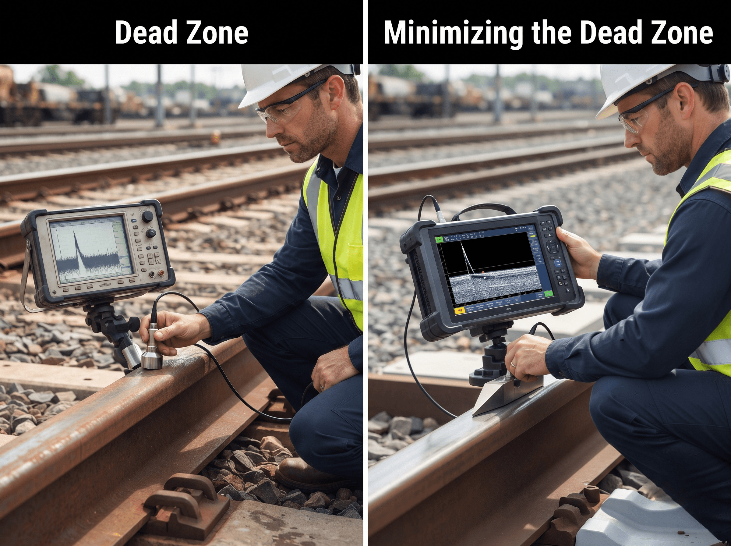
The dead zone in ultrasonic testing is the depth just below the entry surface where a single-element pulse-echo probe can't show a reflector, because the initial pulse, the crystal's ring-down and the receiver's recovery still fill the screen. In steel, every 1 µs of ring-down hides about 3 mm (5.92 mm/µs × 1 µs ÷ 2).
The fix is rarely "more gain". It is a shorter pulse, or a probe that moves the initial pulse out of the part: a delay line, a dual-element (twin-crystal) probe, a water path or a fluid-filled wheel. This guide covers what causes the dead zone, how it differs from the near field, how to measure it on a reference block, how to reduce it, the far-side (back-wall) dead zone, and what it means for rail running-surface defects and thin sections.
Contents: What it is · Causes · Calculating its depth · Dead zone vs near field · Measuring it · Reducing it · Far-side dead zone · Rail · Limits · FAQ
What is the dead zone in ultrasonic testing?
The dead zone is the time, and the matching depth, right after the probe fires during which returning echoes can't be detected. The British Institute of Non-Destructive Testing defines it this way:
"DZ – Dead Zone is the name given to the period immediately after the transmit spike has been applied to an ultrasonic crystal. The crystal oscillates for a number of cycles and these oscillations prevent the detection of received echoes during this period." — BINDT, Index of acronyms: DZ
BINDT adds that the dead zone can be given in units of time or, more commonly in contact testing, as how far it extends below the surface in millimeters. In single-crystal contact testing, it is the ringing seen at the start of the A-scan.
Three terms are often used for the same idea:
| Term | Usually means | Where you'll see it |
|---|---|---|
| Dead zone | Depth below the entry surface where no reflector can be resolved from the initial pulse | Probe data sheets, training, BINDT; defined for probes in BS EN 12668-2:2010 (now EN ISO 22232-2:2020) |
| Entry surface resolution (near-surface resolution) | The smallest depth at which a stated reflector can be resolved from the initial pulse or interface echo | ASTM E317-21, section 1.1 |
| Initial pulse zone or "main bang" | The screen region the transmit pulse occupies | Shop and field usage |
The dead zone belongs mainly to single-element contact probes. Dual-element probes, delay lines, immersion and wheel probes all exist largely to get around it.
Key takeaway: the dead zone is a time window turned into a depth by the velocity of the material; it isn't a fixed property of "ultrasonic testing".
What causes the dead zone?
Two things set the dead zone: how long the transducer keeps ringing after the excitation pulse, and how long the receiver takes to recover from that pulse. The coupling, the frequency and the gain all change it, but they act through these two.
The initial pulse and ring-down
A pulse-echo flaw detector excites the crystal with a large voltage spike, and the echoes it then has to detect are a tiny fraction of that spike. A piezoelectric element doesn't stop moving when the spike ends. It keeps oscillating for a number of cycles, the way a bell keeps sounding after it is struck. The backing material behind the element absorbs that motion; the more heavily the element is damped, the fewer cycles it rings.
Evident describes pulse duration as "the number of wave cycles generated by the transducer each time it is pulsed" and lists element diameter, backing material, electrical tuning and excitation method as the factors that change it (Evident, Transducer characteristics).
The number of cycles matters because each cycle lasts 1/f. A pulse that rings for five cycles lasts 2.22 µs at 2.25 MHz but only 1.0 µs at 5 MHz and 0.5 µs at 10 MHz. That is why, for the same damping, a higher frequency gives a shorter dead zone, not a longer one.
Receiver recovery
The receiver amplifier sees the transmit spike too. At normal inspection gain it is driven into saturation every time the pulser fires, and it needs time to come back. An Olympus NDT patent puts it plainly: "once an amplifier goes into saturation, it takes a significant amount of time for the amplifier to return to the linear region of operation." The same patent says the settling time of the transmitted pulse's trailing edge to the zero baseline "is a determining factor of a flaw detector's near surface resolution" (US 8,001,842 B2, granted 2011).
Filters can lengthen the tail. The patent notes that filters which aren't critically damped make the trailing edge worse after the amplifier leaves saturation. So the same probe can show a different dead zone on two instruments, or on one instrument with a different filter or pulser setting.
What changes the dead zone, and in which direction
| Factor | Effect on dead zone | Why |
|---|---|---|
| Higher frequency, same damping | Shorter | Each cycle is shorter, so the same number of cycles takes less time |
| Heavier damping (broadband probe) | Shorter | Fewer ring-down cycles; costs some sensitivity |
| Lightly damped, narrowband probe | Longer | More cycles of ringing; more energy and sensitivity |
| Larger element at the same frequency | Can be longer | More stored energy to ring down; check the data sheet |
| Higher pulser voltage or energy setting | Can be longer | Bigger spike, deeper saturation, longer recovery |
| Higher receiver gain | Longer on screen | The ringing tail stays above the screen threshold for longer |
| Narrowband or poorly damped filters | Longer | Filter ringing adds to the trailing edge |
| Thick couplant layer or a wear face | Slightly longer, and adds its own echoes | Reverberation inside the layer before sound enters the steel |
| Delay line, water path, dual element | Moved out of the part | The initial pulse ends before sound reaches the steel, or the receiver never sees it |
The draft that this page replaces said high-frequency probes ring longer. That is backwards. Evident's own product note says "Higher transducer frequency improves resolution" (Evident replaceable delay line transducers).
Key takeaway: count the ring-down in microseconds, not in cycles; the same cycle count at twice the frequency halves the dead zone.
How do you convert ring-down time into dead-zone depth?
Dead-zone depth = velocity × ring-down time ÷ 2. The division by 2 is there because the echo has to travel down and back, exactly as in the pulse-echo thickness formula.
Worked example 1: three probes on steel
Steel longitudinal velocity is taken as 5,920 m/s (5.92 mm/µs), a common default; Evident lists 5,890 m/s for 1020 steel, so calibrate on the actual material. The ring-down times below are illustrative inputs, not specifications for any named probe. Read the real value off your own screen as described in the measurement section.
| Probe | Time from the start of the pulse until the trace is back below your threshold | Dead-zone depth in steel |
|---|---|---|
| 2.25 MHz, lightly damped | 3.0 µs | 5.92 × 3.0 ÷ 2 = 8.9 mm (0.35 in.) |
| 5 MHz, medium damping | 1.0 µs | 5.92 × 1.0 ÷ 2 = 3.0 mm (0.12 in.) |
| 5 MHz, heavily damped | 0.6 µs | 5.92 × 0.6 ÷ 2 = 1.8 mm (0.07 in.) |
| 10 MHz, broadband | 0.4 µs | 5.92 × 0.4 ÷ 2 = 1.2 mm (0.05 in.) |
Two points follow from the arithmetic.
First, a flaw at 3 mm depth returns its echo 1.01 µs after the pulse (2 × 3 ÷ 5.92). On the medium-damped 5 MHz probe that echo lands on the very end of the ringing, so it may be visible as a bump on the tail but can't be reliably resolved or sized.
Second, the same time window means a different depth in a different material. In aluminum or in a plastic wedge the depth per microsecond is smaller, so "dead zone = 3 mm" is only meaningful with the material and the velocity stated.
How is the dead zone different from the near field?
The dead zone is an electronic and transducer-ringing effect measured in time; the near field is a beam-physics effect measured in distance. They both sit near the probe, and they are often confused, but they have different causes, different sizes and different fixes.
The near field (the Fresnel zone) is the region in front of a probe where waves from different parts of the element interfere, so echo amplitude rises and falls with distance even for identical reflectors. Its length is N = D²f / 4v. A 10 mm, 5 MHz probe in steel has N = 10² × 5 ÷ (4 × 5.92) = 21.1 mm. The same probe might have a dead zone of only 2 to 3 mm.
| Dead zone | Near field | |
|---|---|---|
| Cause | Initial pulse, crystal ringing, receiver recovery | Interference across the face of the element |
| What you lose | The ability to see any echo at all | Reliable amplitude (sizing and DAC), not detection |
| Typical size for a 10 mm, 5 MHz contact probe in steel | A few mm | About 21 mm |
| Effect of higher frequency | Shorter | Longer (N grows with f) |
| Effect of a larger element | Can be longer | Much longer (N grows with D²) |
| Main fix | Shorter pulse, delay line, dual element, water path | Choose the element size and frequency, or put the near field inside a delay line |
Raising the frequency shortens the dead zone and lengthens the near field, so the two can't be treated as one "near-surface problem". A reflector at 10 mm under that 10 mm, 5 MHz probe is well clear of the dead zone, so it is detected. It is still inside the near field, so its amplitude can't be trusted for sizing.
For near-field formulas, angle-beam corrections and DAC point placement, see Near field vs far field in UT.
Key takeaway: an echo inside the near field can be seen but not sized by amplitude; an echo inside the dead zone can't be seen at all.
How do you measure the dead zone on a reference block?
Place the probe so that a reflector at a known, shallow depth is in the beam, and find the shallowest depth at which its echo is clearly separated from the initial pulse. That depth is the measured dead zone for that probe, cable, instrument and setting, and it should be recorded in the procedure or setup sheet.
What the standards say
ASTM E317-21, Evaluating Performance Characteristics of Ultrasonic Pulse-Echo Testing Instruments and Systems without the Use of Electronic Measurement Instruments, is the active US practice that covers this check. Its scope lists "Resolution - Entry Surface and Far Surface" among the characteristics evaluated, and it uses selected test blocks rather than electronic test equipment.
E317 deliberately sets no pass mark. Its scope says it "establishes no performance limits for examination systems" and that acceptance criteria, where needed, "must be specified by the using parties". Section 5.7 also says no evaluation frequency is "recommended or implied". The limit and the interval come from your procedure, the referencing code or the contract. ASTM's companion, E1324-21(2026), measures the instrument's electronics (pulse shape, rise time, receiver response) with laboratory equipment and complements E317; it does not replace it.
In ISO and EN practice, the probe dead zone was defined in EN 12668-2, which EN ISO 22232-2:2020 replaced. BINDT notes that BS EN ISO 16811:2014 covers the effect of the dead zone when setting a DAC, which is why a DAC point must not be taken from an echo that sits on the tail of the initial pulse.
Which block to use
The IIW-type calibration block (ISO 2400 "No. 1" block; ASTM E164 IIW-type blocks) is built mainly for angle-beam work: probe index, beam angle and time base. Published descriptions of both standards say it also provides straight-beam resolution checks, but they don't give one dead-zone procedure, and training procedures differ on which block feature to use. Treat an IIW-block reading as a coarse bracket.
For a real number, use a block with reflectors at a series of shallow depths: a step block, or a resolution block with flat-bottom or side-drilled holes close to the entry surface, in the same material as the part. Some procedures step the probe across a block with 1 mm steps to find the exact value.
A field procedure
- Set up as for the inspection: the same probe, cable, pulser voltage, damping, filter and gain. Changing any of these changes the dead zone.
- Calibrate the time base in depth for the test material.
- Couple the probe over the deepest of the shallow reflectors and confirm a clean echo.
- Move to progressively shallower reflectors. At each, check whether the echo rises clearly out of the ringing tail. Your procedure should state the criterion, for example the echo peak standing a stated amount above the trough between it and the initial pulse.
- Record the shallowest depth that meets the criterion as the dead zone (or entry surface resolution) for that setup, with the block, reflector type and gain.
- Repeat after changing probe, cable or instrument, and at the intervals your procedure sets.
Key takeaway: a dead-zone value is only valid for the exact probe, cable, instrument and gain it was measured with, and ASTM E317 leaves the pass mark to you.
How can you reduce the dead zone?
Shorten the pulse, or move the initial pulse out of the part. The first approach trims the dead zone; the second removes most of it from the steel.
| Method | How it works | Typical use | Trade-off |
|---|---|---|---|
| Higher frequency | Shorter cycles, shorter ring-down | Thin parts, near-surface flaws | Less penetration, more scatter in coarse grain |
| Heavier damping (broadband probe) | Fewer ringing cycles | Thickness and near-surface work | Lower sensitivity |
| Lower gain and pulser energy, clean filters | Less saturation, faster recovery | Fine-tuning a setup | Less sensitivity to small, deep flaws |
| Delay-line probe | Initial pulse rings out inside the delay | Thin material, hot parts, contoured surfaces | Interface echo and its multiples limit the usable thickness |
| Dual-element (twin-crystal) probe | Separate transmitter and receiver; receiver never sees the spike | Corrosion and remaining-wall surveys, rough surfaces | V-path error at small thickness; focused depth range |
| Immersion or water column | Water path delays the part's front-surface echo | Shop testing of plate, bar and tube | Needs a tank or bubbler; water multiples |
| Fluid-filled wheel or sled probe | Fluid path acts as a delay line in motion | Rail test cars and carts | Surface noise and coupling, not ringing, limit the top of the head |
| Angle beam | Near-surface depth is reached at a longer sound path | Weld and rail head inspection | The wedge has its own internal echoes |
Higher frequency and damping
A heavily damped, higher-frequency probe gives the shortest pulse. Evident's description of its replaceable delay line transducers states that a "Heavily damped transducer combined with the use of a delay line provides excellent near surface resolution." The cost is penetration and sensitivity. In coarse-grained material, a higher frequency also raises grain scatter, so 10 MHz is not a free upgrade on a casting.
Delay-line probes
A delay line is a plastic tip between the element and the part. The initial pulse and ring-down happen while sound is still traveling through the plastic, so by the time the first echo from inside the steel returns, the transducer has settled. Evident says delay lines are used "where it is important to separate the excitation pulse recovery from back wall echoes" (Evident, Thickness gauge transducers).
The near-surface limit doesn't vanish. It moves to the interface echo (the echo from the delay tip against the steel), which has its own width. And the delay line's own second echo eventually arrives and sets a maximum thickness.
Worked example 2: what a 10 mm acrylic delay line does
Inputs: acrylic longitudinal velocity 2,730 m/s (2.73 mm/µs) and steel 5,920 m/s, both from Evident's velocity table (steel rounded to the common default). Delay length 10 mm.
| Step | Calculation | Result |
|---|---|---|
| Round trip in the delay line | 2 × 10 ÷ 2.73 | 7.33 µs |
| Equivalent steel depth hidden by that time | 5.92 × 7.33 ÷ 2 | 21.7 mm |
| A 3.0 µs ring-down (from example 1) | ends at 3.0 µs, before the interface echo at 7.33 µs | ring-down no longer reaches the steel |
| Second delay-line echo (first multiple) | 2 × 7.33 | 14.65 µs |
| Clean steel window | from the interface echo (7.33 µs) to the multiple (14.65 µs) = 7.33 µs of steel time | back walls up to about 21.7 mm of steel |
| New near-surface limit if the interface echo takes 0.5 µs to settle | 5.92 × 0.5 ÷ 2 | about 1.5 mm |
So a 10 mm acrylic delay line converts a dead zone set by the probe's full ring-down into one set by the interface echo's width, here from as much as 8.9 mm down to about 1.5 mm. In exchange, the probe works cleanly only on steel up to about 21.7 mm thick before the delay line's own multiple lands among the steel echoes.
A rail check of the same setup: a 136RE web is 11/16 in. (17.5 mm) thick. Measured from the side with this delay line, its back-wall echo arrives at 7.33 + 2 × 17.5 ÷ 5.92 = 13.24 µs, before the multiple at 14.65 µs, so the reading is clean.
Dual-element probes
A dual-element probe has a transmitting crystal and a receiving crystal side by side, separated by an acoustic barrier and usually mounted on angled delay blocks. Because the receiver is not the element that was struck by the transmit spike, it doesn't have to ring down or recover from it. BINDT notes that twin-crystal probes are used "to overcome the problem of the DZ" and to inspect close to the surface.
Evident states that dual-element transducers improve near-surface resolution and gives one series of 7.5 MHz duals an optimal near-surface resolution range of 0.030 to 2 in. (0.76 to 50.8 mm) in steel. Evident also says duals are "used primarily for measurements involving rough, corroded surfaces." Two limits apply. Duals are most sensitive where the two beams cross, so their useful depth range is set by the roof angle. And at small thicknesses the angled V-shaped sound path reads long; thickness gauges correct this with built-in tables, while general flaw detectors usually don't.
Immersion and wheel probes
In immersion testing, the water path acts as a very long delay line. Evident notes that the front-surface echo in an immersion setup is used as the zero reference for depth.
Worked example 3: minimum water path for a 25 mm steel plate
The water path must be long enough that the second front-surface echo (the water multiple) arrives after the back-wall echo.
| Step | Calculation | Result |
|---|---|---|
| Steel round trip, 25 mm plate | 2 × 25 ÷ 5.92 | 8.45 µs |
| Water path W giving the same round trip (water 1.48 mm/µs) | 25 × 1.48 ÷ 5.92 | 6.25 mm |
| Rule of thumb seen in training material (not found in a standard) | thickness ÷ 4 + 6 mm | 12.25 mm |
The physics gives W > T × v_water / v_steel, which is about one quarter of the steel thickness. Training material often adds a margin of about 6 mm (1/4 in.); use whatever your governing procedure states.
Rail test cars and carts apply the same idea in motion. Patents for rail test equipment describe transducers "contained within a fluid-filled wheel" with a water spray on the rail to couple the tire (US 5,777,891, 1998). The fluid inside the tire is a delay path, so the initial pulse rings out before sound enters the rail head. A vendor application note adds that tilting a wheel probe can change the refracted angle in the metal, so the alignment matters as much as the delay.
Angle beam and the near-surface depth
An angle-beam probe reaches a shallow depth at a longer sound path, because depth = sound path × cos θ. At 70°, cos θ = 0.342. A zone of 6 mm of sound path near the start of the trace corresponds to only 6 × 0.342 = 2.1 mm of depth. The probe's own ring-down is also mostly spent inside the wedge. The trade-off is that the wedge produces its own internal echoes, and the near-surface region is then limited by wedge noise and surface-wave signals rather than by ringing.
What doesn't reduce the dead zone
- Time-corrected gain (TCG/TVG) or DAC. These compensate for attenuation and beam spread with depth. Evident describes TVG as bringing reference echoes "to the same height". They don't shorten the transmit pulse or the receiver's recovery, and they shouldn't be set with a reference point that sits on the initial pulse.
- More gain. Raising gain makes the ringing tail stay on screen longer, so the visible dead zone gets deeper.
- Better couplant alone. Poor coupling causes signal loss and noise, which is a separate problem from the dead zone. A thick, uneven couplant layer can add reverberations near the start of the trace, but good coupling doesn't remove the ring-down.
- Software claims. Signal processing can clean a trace, but claims that machine learning "eliminates" the dead zone have no published field basis. If the receiver is saturated, the echo information is lost before any software sees it.
Key takeaway: if a reflector must be found within a few millimeters of the entry surface, change the probe type, not the gain.
What is the far-side or back-wall dead zone?
The far-side dead zone is the thin layer just above the back wall where a flaw's echo merges with the much larger back-wall echo. ASTM E317 calls the ability to separate them "far surface resolution".
The physics is the same pulse-length problem in reverse. A flaw 1 mm above a 25 mm back wall returns its echo only 2 × 1 ÷ 5.92 = 0.34 µs before the back wall. If the back-wall pulse is 0.6 µs long, the two echoes overlap and the flaw shows only as a broadened or distorted back-wall signal. With a 0.6 µs pulse, the zone in which a flaw can't be separated from the back wall is about 5.92 × 0.6 ÷ 2 = 1.8 mm.
Three things make the far-side zone worse:
- Saturation by the back wall. If gain is set high enough to show small flaws, the back-wall echo saturates the receiver, and a near-back-wall flaw can disappear in its trailing edge. Gating the back wall separately helps.
- Beam spread and edge effects. Near a corner or a curved back surface, beam edges and mode-converted signals add confusing echoes.
- TOFD. In time-of-flight diffraction the back-wall dead zone is a defined term (BS EN ISO 16828), alongside the lateral-wave dead zone at the top. TOFD dead zones need their own geometry; see TOFD rail inspection.
A back-wall loss is also a signal in its own right. When a reflector near the far side doesn't show as an echo, the drop in back-wall amplitude may be the only sign of it.
Key takeaway: check both ends of the trace; a setup can resolve 2 mm below the surface and still hide a flaw 2 mm above the back wall.
Why does the dead zone matter in rail inspection?
The rail defects most affected are the ones that start at or near the running surface, and the sections most affected are the thin ones measured by hand. Test cars and carts largely avoid the classic dead zone by using fluid-filled wheels or sleds and angled beams, so the near-surface limits in rail are usually surface noise and masking, not ring-down.
It is a mistake to describe the near-surface blind zone as a general weakness of rail UT. A dead zone belongs to single-element contact probes; duals, angle paths and wheel or sled delay paths cover the rail head. FRA's 2014 rail integrity rule describes UT as the primary rail flaw method in use, with test frequencies "normally" from 2.25 to 5.0 MHz, and lists surface conditions that "negatively influence the detection of rail flaws", including shells, engine driver burns, spalling, flaking, corrugation and head checking (79 FR 4234, January 24, 2014).
Running-surface and near-surface defects
| Defect | Where it starts | Published depth | What limits UT |
|---|---|---|---|
| Head checks (gauge corner cracking) | At or very close to the surface | Typically grow to 2–5 mm deep at 10°–30° (ARTC RC 2400) | Too shallow for a 0° dead zone to matter; they scatter and mask the beam |
| Flaking | Running surface | About 1/32 in. deep (transit training material) | Surface condition, not a UT target |
| Shelling | Below the gauge corner | 1/4 to 3/8 in. (6.4 to 9.5 mm) on FAST high rails (TTCI TD-10-004); 2–8 mm (ARTC) | The shell blocks the beam from what lies beneath it |
| Horizontal split head | Inside the head | Usually at least 1/4 in. (6.35 mm) below the running surface (49 CFR 213.113(d)) | Normally clear of the dead zone for a wheel or dual setup |
| Squats | Running surface | Surface-initiated; trailing crack at about 30° | Branch cracks shielded by the trailing crack are often missed by conventional UT (FRA ORD-11/24) |
| Detail fracture | At or near the head surface, from shelling, head checks or flaking (213.113(d)) | Varies | Masking by the surface damage above it |
TTCI's study of rails removed for low-confidence UT found 880 rolling contact fatigue cracks and spalls, 90% of them no more than 0.040 in. (1.0 mm) deep, and suggested that production grinding would likely have improved UT confidence (TTCI TD-18-027). At that depth no pulse-echo probe resolves the cracks themselves. What matters is that the surface damage scatters sound and masks deeper transverse defects. That is a masking and surface-preparation problem, which is why grinding, and surface methods such as eddy current, are used alongside UT. See Rail shelling and spalling and Head checks in rail.
Hand verification and thin sections
The dead zone becomes a practical issue when a technician verifies a suspect by hand with a contact probe, or measures remaining thickness on a corroded web or base. A 136RE web is about 17.5 mm (11/16 in.) thick when new. On a single-element 2.25 MHz probe with an 8.9 mm dead zone (example 1), half that web would be hidden, and on a corroded web it could be most of it.
For those readings:
- use a dual-element or delay-line probe sized for the expected thickness;
- confirm the setup on a step block covering the thinnest expected value, so you know where the dead zone and the V-path error begin;
- treat a reading near the probe's minimum as unconfirmed until checked with a second method or probe.
Rail head and base geometry
A 0° wheel probe on a 136RE rail (height 7-5/16 in., 185.7 mm) sees the base echo at about 62.7 µs. A flaw in the bottom millimeter or two of the base sits in the far-side zone of that echo, and the 0° response to it is often a loss of base echo rather than a separate echo. At the top, the fluid path in the wheel keeps the ring-down out of the rail head, and the 70° beams reach the upper head along long sound paths. The angled path is 1/cos 70° = 2.92 times the depth.
Key takeaway: on rail, the near-surface question is usually "is the surface letting sound in?" rather than "is the probe still ringing?", except during hand verification and thickness work.
What the dead zone means for what UT cannot do
No pulse-echo setup sees all the way to either surface, and an inspection plan should say so. These are the practical limits:
- A surface-breaking crack shallower than the dead zone isn't found by straight-beam pulse-echo. It needs an angle beam that strikes it as a corner reflector, a surface method (MT, PT or eddy current), or visual inspection.
- A clear screen in the dead zone proves nothing. If the ringing hides the first 3 mm, the report should not imply that the first 3 mm were examined.
- Measured dead zones don't transfer. A value from one probe, cable and instrument doesn't apply to another, and probes wear. Re-measure when the setup changes.
- Dual and delay-line probes have their own limits. Duals have V-path error and a focused depth range; delay lines have interface echoes, multiples and wear.
- The near field still applies beyond the dead zone. An echo that is visible may not be sizeable by amplitude.
- Surface condition can matter more than ringing. On rail, shelling and RCF can block the beam entirely. Lost coupling is untested rail, not a sound reading.
- Codes don't set a universal dead-zone limit. ASTM E317 sets no limits; the requirement has to come from the procedure, the referencing code or the contract.
How EMA Industries applies this
EMA Industries performs ultrasonic rail flaw testing for transit agencies, short lines and industrial track owners, plus AWS D1.1 structural weld UT and NDT Level III services, from Southern California with nationwide mobilization. On any UT scope, the procedure should state the measured entry-surface and far-surface resolution for each probe used, the block it was measured on, and how near-surface regions are covered by another probe or method. That applies to hand verification of rail suspects and to remaining-wall readings on corroded webs. If you need a procedure reviewed, or a rail or weld UT scope written so it says what the dead zone leaves uncovered, contact EMA Industries.
Related reading: Near field vs far field in UT · TOFD rail inspection · DAC curve in ultrasonic testing · Ultrasonic testing formulas · Thickness gauge or flaw detector? · Ultrasonic couplant for rail inspection · Rolling contact fatigue in rail
Frequently asked questions
What is meant by dead zone in ultrasonic testing?
It is the region just below the entry surface where a pulse-echo probe can't resolve a reflector, because the transmit pulse, the crystal's ringing and the receiver's recovery still occupy the start of the trace. It is a time window, converted to depth by velocity × time ÷ 2.
How do you reduce the dead zone in ultrasonic testing?
Use a shorter pulse (higher frequency, heavier damping, lower pulser energy and gain), or move the initial pulse out of the part with a delay-line, dual-element, immersion or fluid-filled wheel probe. Time-corrected gain and DAC don't reduce it.
Is a smaller dead zone always better?
For near-surface work it is, but the probes that give the smallest dead zone, such as highly damped, high-frequency or dual probes, trade away penetration, sensitivity or depth range. Choose the probe for the depth band that must be covered, and use a second probe for the rest.
How deep is a typical dead zone in steel?
It ranges from under 1 mm for duals and delay-line probes to several millimeters for single-element contact probes. A lightly damped 2.25 MHz probe ringing for 3 µs hides about 8.9 mm. Measure your own setup rather than quoting a typical value.
Does the dead zone affect angle-beam and TOFD inspection too?
Angle-beam probes spend most of their ring-down inside the wedge, and at 70° a short sound path corresponds to a small depth, so wedge noise is usually the near-surface limit. TOFD has its own lateral-wave and back-wall dead zones, which are covered on the TOFD rail inspection page.
Sources
- BINDT, Index of acronyms: DZ (Dead Zone), British Institute of Non-Destructive Testing
- ASTM E317-21, Evaluating Performance Characteristics of Ultrasonic Pulse-Echo Testing Instruments and Systems without the Use of Electronic Measurement Instruments, ASTM International (Active)
- ASTM E1324-21(2026), Measuring Some Electronic Characteristics of Ultrasonic Testing Instruments, ASTM International
- US 8,001,842 B2, Ultrasonic fault detection system using a high dynamic range analog to digital conversion system, Olympus NDT, 2011
- US 5,777,891, rail flaw detection with fluid-filled wheel transducers, 1998
- Evident, Transducer characteristics
- Evident, Thickness gauge transducers
- Evident, Replaceable delay line transducers
- Evident, Sound velocities in materials
- Evident, Delay line and immersion transducer setup
- Track Safety Standards; Improving Rail Integrity, 79 FR 4234 (January 24, 2014), Federal Register
- 49 CFR 213.113, Defective rails, eCFR
- TTCI TD-18-027, RCF and UT confidence (Cummings, November 2018), MxV Rail
- TTCI TD-10-004, Shelling on high rails (Szablewski and Robles Hernández, March 2010), MxV Rail
- FRA ORD-11/24, rail rolling contact fatigue report (2011), ROSA P
- ARTC RC 2400, Rail Defects Handbook (2006), Australian Rail Track Corporation