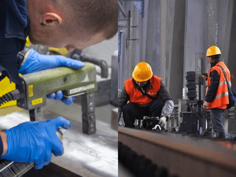
Magnetic particle examination (MT) is a surface NDT method that finds cracks at or just below the surface of ferromagnetic steel by magnetizing the part and applying fine iron particles. Under ASME Section V, Article 7, each area is examined twice, in field directions about 90° apart, and an AC yoke must lift at least 10 lb.
MT is the normal surface method for carbon steel welds, railcar axles, wheels and cast truck components. It is not the routine method for rail in track, and it doesn't work at all on the austenitic manganese steel used in most mainline frogs.
What is magnetic particle examination, and what can it find?
Magnetic particle examination magnetizes a ferromagnetic part so that a crack at or near the surface forces some of the magnetic flux out into the air, where it holds a line of iron particles. The indication is wider and easier to see than the crack.
Flux leaks only where a discontinuity cuts across it. A crack parallel to the field gives little or no indication, so field direction matters more than anything else in an MT procedure.
MT works only on ferromagnetic material: carbon and low-alloy steels, most cast irons and martensitic stainless steels. ASTM's general-industry practice, E3024/E3024M-22a, states that MT "is not applicable to non-ferromagnetic metals and alloys such as austenitic stainless steels". Aluminum, copper alloys and austenitic manganese steel are out for the same reason.
Depth reach is limited. A Colorado DOT bridge procedure for continuous AC yoke testing with dry visible powder (QAP 5930, 2018) says subsurface discontinuities "can not be reliably detected" beyond about 1/64 in. from the surface with that technique. DC reaches somewhat deeper, but MT is never a volumetric method.
Key takeaway: MT finds surface and slightly subsurface cracks in ferromagnetic steel, and only when the field crosses the crack.
Yoke, prods or coil: which magnetizing technique fits the job?
A yoke suits most field weld work, prods suit heavy sections where arc strikes are acceptable, and coils or head shots suit shop parts such as axles. The choice depends on access, part size and whether the surface can tolerate electrical contact.
| Technique | How it magnetizes | Field it makes | Typical use | Main drawback |
|---|---|---|---|---|
| Electromagnetic yoke (AC, DC or AC/DC) | Two poles placed on the part carry flux through the area between them | Longitudinal, pole to pole | Field welds, structural steel, castings, local spot checks | Small area per placement; 1 in. or so near each pole isn't evaluated |
| Prods | Current passes through the part between two hand-held contacts | Circular, around the current path | Thick welds and castings where more field is needed | Arc strikes and local overheating at the contacts |
| Encircling coil | The part sits inside a current-carrying coil | Longitudinal, along the part axis | Axles, shafts, bars | Shop equipment; field strength falls toward the ends of long parts |
| Head shot or central conductor | Current passes through the part or through a bar inside it | Circular | Shafts, rings, tubular parts in a wet bench | Shop only; contact heads can burn the part |
Yokes are the default on structural welds because no current passes through the steel. The Colorado DOT procedure says the prod method "is virtually never used, as arc strikes can be induced by the prods", and Sulzer's MT procedure (TP-0002, Rev. 13, 2024) requires any prod arc strike to be ground out and re-examined with a yoke.
For prods, older copies of ASME Section V, Article 7 (2001 and 2019) cap spacing at 8 in. and set 100–125 A per inch of spacing for sections 3/4 in. or thicker, 90–110 A per inch below that; check the edition in your contract.
On axles, an ASNT Materials Evaluation article (Poudel, January 2024) describes encircling coils magnetizing the axle along its axis, the field direction that shows transverse cracks.
Key takeaway: yokes for welds in the field, coils and head shots for shop parts, prods only when arc strikes are acceptable.
Should you use AC, DC or half-wave DC?
Use AC for surface cracks such as weld-toe and fatigue cracks, and DC or half-wave DC (HWDC) when slightly subsurface flaws must also be found. AC concentrates the field at the surface by the skin effect, while DC penetrates further into the section.
| Current | Field depth | Particle mobility | Typical use |
|---|---|---|---|
| AC | Shallow (skin effect) | Good: the alternating field makes particles move toward leakage sites | Weld toes, fatigue cracks, grinding cracks, in-service surface cracks |
| Half-wave rectified DC (HWDC) | Deeper than AC | Good: the pulsing current helps dry powder move | Dry powder on rough welds and castings where near-surface flaws matter |
| Full-wave rectified or straight DC | Deeper than AC | Lower than AC or HWDC | Shop benches and coils where subsurface sensitivity is needed |
Published guides disagree on whether HWDC or full-wave DC reaches deeper, so don't put a depth figure on either without a source. AC remains the right choice for surface-open fatigue and weld-toe cracks.
DC leaves more residual magnetism, so parts to be machined or welded again may need demagnetizing.
Key takeaway: AC for surface cracks, DC or HWDC for near-surface work, with demagnetization planned when DC is used.
Wet fluorescent or dry visible particles?
Wet fluorescent particles give the highest sensitivity to fine surface cracks, while dry visible powder works better on rough, warm or outdoor surfaces. The trade is sensitivity against convenience.
| Particle system | Viewing | Best for | Limits |
|---|---|---|---|
| Wet fluorescent (oil or water carrier) | UV-A in a darkened area | Fine cracks on smooth surfaces; shop axles, wheels, castings | Needs darkness, UV-A lamp and bath checks; carrier temperature limits from the manufacturer (one procedure gives about 122 °F, 50 °C) |
| Wet visible (black or red) | White light, often over white contrast paint | Field welds where darkness isn't practical | Lower sensitivity than fluorescent |
| Dry visible powder (red, gray, yellow) | White light | Rough as-welded or cast surfaces; with HWDC for near-surface flaws | Least sensitive to very fine cracks; wind and surface moisture disturb it |
TTCI's Technology Digest TD-09-009 (Carter, March 2009) compared methods on freight car side frames, bolsters and knuckles and found "the wet fluorescent method was the most dependable method for finding finer surface indications", followed by dry magnetic particle, then liquid penetrant.
Key takeaway: wet fluorescent in the shop for the finest cracks, dry or wet visible in the field.
Why must each area be magnetized in two directions?
Each area is examined twice, with the second field about 90° to the first, because a crack parallel to one field direction gives no indication in that direction. Two passes at right angles catch cracks of any orientation.
The Colorado DOT procedure puts the rule in the words most procedures use: "At least two separate examinations shall be performed on each area." The second examination must have flux lines "approximately perpendicular" to the first. Sulzer's procedure allows the angle between the two to range from 50° to 130° where geometry prevents a true 90°.
On a weld, the two directions map to the two crack families:
| Yoke placement | Field direction | Cracks it finds |
|---|---|---|
| Poles on either side of the weld | Across the weld | Longitudinal cracks: toe cracks, centerline cracks, lack of fusion at the toe |
| Poles along the weld | Along the weld | Transverse cracks across the weld or heat-affected zone |
Sulzer's procedure requires at least 10% overlap between placements and treats about 1 in. (25 mm) around each pole as not testable, so pole spacing sets how far the yoke moves between shots.
Key takeaway: two directions about 90° apart, with overlap, or the examination isn't complete.
How is a yoke checked before use?
A yoke is checked with a lift test, and the field at the part is checked with an indicator such as a pie gauge or artificial flaw shims. The lift test proves the yoke's strength; the indicator proves the field is present and pointing the right way on the actual part.
The lift test values depend on which document governs, and that is where most confusion comes from:
| Document | AC yoke | DC yoke | Confidence |
|---|---|---|---|
| ASME Section V, Article 7, T-762 | At least 10 lb (4.5 kg) at the maximum pole spacing to be used | At least 40 lb (18 kg) at the maximum pole spacing | Paragraph number from Magnaflux certificates citing the 2017 edition; values from study guides and a Sulzer procedure (Med, CONFIRM in the current edition) |
| AWS D1.5 bridge code table, as quoted in public copies | 10 lb (45 N) at 2–4 in. spacing | 30 lb (135 N) at 2–4 in.; 50 lb (225 N) at 4–6 in. | Low-Med, CONFIRM |
| ASTM E709-21 | Has its own lifting-power check | Vendor tables disagree on the DC figure | Low, CONFIRM |
So the "30, 40 or 50 lb" DC conflict partly reflects different documents, not only different vendors. Name the governing document in the procedure and lift at the widest spacing you will use.
Field indicators answer a different question. Sulzer's procedure uses the pie-shaped indicator or flaw shims to prove "the presence and the direction of the magnetization only"; field strength needs a calibrated gaussmeter.
Key takeaway: lift test for the yoke, pie gauge or shims for the field on the part, and name the code that sets the lift weight.
How clean must the surface be, and can MT go through paint?
MT needs less preparation than penetrant testing, but it still needs a dry surface free of loose scale, oil, heavy rust, spatter and thick paint. "Minimal preparation" and "thorough preparation" are both true in a narrow sense: MT tolerates thin coatings and rougher surfaces than PT, but contamination that hides particles or lifts the yoke still causes missed indications.
The Colorado DOT procedure requires a test area that is "clean, dry, and free from contaminants", listing oil, grease, loose rust, loose scale, lint, thick paint, sand, flux and spatter. It caps paint on the test surface at 2 mils dry film thickness and asks for sensitivity to be shown on a reference standard when testing through paint. Sulzer's procedure also allows nonmagnetic coatings up to 0.002 in. (0.05 mm) and requires a demonstration for anything thicker.
ASME Section V uses a demonstration rather than a fixed thickness: where nonmagnetic coatings stay on, indications must be shown detectable through the maximum coating thickness present. Conductive or magnetic coatings need their own demonstration or removal.
Rough as-welded ripples can hold dry powder and mask fine toe cracks, so light grinding or a white contrast coat helps. The Colorado DOT procedure also delays MT on A514, A517 and A852 quenched and tempered steels until 48 hours after welding.
Key takeaway: thin, nonmagnetic coatings up to about 2 mils are usually workable with a demonstration; everything that masks particles comes off.
What lighting does magnetic particle examination need?
Fluorescent MT needs UV-A of at least 1,000 µW/cm² at the surface with ambient white light of 2 fc (about 20 lx) or less, and visible MT needs bright white light at the surface. Confirm the ASME figures below against your contract's edition.
| Item | Typical requirement | Source and confidence |
|---|---|---|
| UV-A intensity at the examination surface | ≥1,000 µW/cm², about 365 nm | Study guides and the Sulzer procedure, citing ASME V (Med, CONFIRM) |
| Ambient white light during fluorescent viewing | ≤2 fc (about 20 lx); Sulzer uses ≤21.5 lx | Study guides; Sulzer (Med) |
| Dark adaptation before viewing | At least 5 minutes | Study guides; Sulzer (Med) |
| UV-A lamp warm-up | At least 10 minutes for non-LED lamps (Sulzer) | Procedure (Med) |
| White light for visible particles | 100 fc (about 1,000 lx) at the surface; Sulzer uses ≥1,076 lx | ASME V study guides (Med, CONFIRM) |
| White light in a D1.5 bridge procedure | 32.5 fc minimum | Colorado DOT QAP 5930 (High for that procedure) |
Measure light at the examined surface with a calibrated meter; a weld toe under a girder flange can fall well below the requirement even when the work area looks bright.
Key takeaway: measure UV-A and white light at the examination surface, and don't carry one document's figure into another document's job.
Which standards govern magnetic particle examination?
Technique standards (ASTM E709, E3024, E1444 and ASME Section V, Article 7) say how to examine; acceptance comes from the construction code or contract, such as AWS D1.1. ASTM E709-21 says so directly:
"This guide does not indicate, suggest, or specify acceptance standards for parts/pieces examined by these techniques." (ASTM E709-21, section 1.3)
| Document | What it is | Use it for |
|---|---|---|
| ASTM E709-21, Standard Guide for Magnetic Particle Testing | A guide covering dry and wet techniques "at or near the surface in ferromagnetic materials"; useful for preventive maintenance testing; refers explicit requirements to a written procedure | Writing and reviewing MT procedures; D1.1 refers to it (study guides) |
| ASTM E3024/E3024M-22a, Magnetic Particle Testing for General Industry | Minimum requirements for industrial MT; refers aerospace work to E1444 | Shop and industrial specifications, including rail equipment where a contract cites ASTM |
| ASTM E1444/E1444M-26, Magnetic Particle Testing for Aerospace | Minimum requirements for aerospace MT using the wet fluorescent method; replaces MIL-STD-1949 | Aerospace work only. Older specifications that cite E1444 for industrial parts predate the split; check which document the buyer means |
| ASME BPVC Section V, Article 7 | MT methods required by other ASME sections; no acceptance criteria | Pressure vessel and piping work, and any contract that invokes it |
| AWS D1.1/D1.1M:2025-AMD1 | Structural Welding Code – Steel; inspection in Clause 8 | MT of structural steel welds when the contract calls for it, judged against D1.1 criteria |
| AWS D1.5 (AASHTO/AWS) | Bridge Welding Code | Steel bridges, including AREMA-designed railroad bridges |
| AAR MSRP specifications (M-101 axles, M-107/M-208 wheels) | Freight car component specifications in MSRP Section G | Wheel and axle work under AAR rules |
| AAR M-1003 | The AAR quality assurance specification | Supplier quality systems. It is not an MT technique standard, so don't cite it as one |
The ASTM split matters for procurement: E1444/E1444M-26 (May 2026) is scoped to aerospace and E3024/E3024M is the general-industry practice, so a rail or structural specification citing "E1444" for field welds is probably out of date.
Study guides for D1.1:2025 place MT in Clause 8 with ASTM E709 as the practice; confirm the clause numbers in your contract's edition.
Key takeaway: cite E709 or E3024 (or ASME V Article 7) for the technique and the construction code for acceptance.
Where is magnetic particle examination used in railway maintenance?
On the railroad, MT is used mainly on rolling stock components (axles, wheels, truck castings and couplers) and on welds, not on rail in track. Each application has its own driver and its own limits.
| Component | Is MT normal? | Typical technique | Notes |
|---|---|---|---|
| Freight car axles | Yes, in wheel shops | Wet fluorescent; encircling coil for transverse cracks | AAR standards recommend MT during wheel and roller bearing replacement (ASNT Materials Evaluation, 2024). MT can't find internal voids; UT covers the volume |
| Wheels | Yes, in shops, alongside UT | Wet fluorescent or visible | AAR M-107/M-208 cover wrought and cast steel wheels; check the AAR manual for the inspection method required |
| Side frames, bolsters, knuckles (truck and coupler castings) | Yes | Wet fluorescent in manufacturing; dry MT in car shops (TTCI recommendation) | TD-09-009: dry MT for side frames and knuckle pulling faces, dry MT plus PT for bolsters in car shops |
| Locomotive and transit vehicle structures, bogie frames | Common, under the owner's maintenance program | Yoke, visible or fluorescent | Fatigue cracks at weld toes and brackets; frequency set by the owner or builder |
| Railroad bridge steel and structural welds | Yes, when the contract calls for it | AC yoke, dry or wet visible | AWS D1.5 for bridges; D1.1 for buildings and general structures |
| Rail weld repairs (slot welds, head repairs) | Sometimes | Yoke on the ground repair | TTCI TD-04-011 (2004) describes a slot-weld repair whose milled cavity is checked by MT before welding |
| Rail in track | No | n/a | Internal testing under 49 CFR 213.237 is done with rail flaw detection equipment, normally UT |
| Cast austenitic manganese frogs and crossing diamonds | No | n/a | The steel is essentially non-magnetic; PT is the surface method |
FRA research report RR 22-25 (2022) notes that "most of the mainline frogs and crossing diamonds are made with austenitic manganese steel (AMS) castings" and that "revenue service examinations of these special trackwork components currently use only visual inspections." AMS is essentially non-magnetic, so a yoke won't magnetize it; use visual inspection, and PT where a crack must be confirmed.
Key takeaway: MT on rolling stock, castings and welds; not on rail in track, and never on cast manganese.
Is MT used to test rail in track?
No. Rail in track is tested internally under 49 CFR 213.237, normally with ultrasonic equipment, and MT is not a routine in-track method.
The defects that drive 49 CFR 213.237 testing (transverse fissures, detail fractures, split heads, bolt-hole cracks) are internal or hidden behind joint bars. MT can't see them, and 213.237(f) requires equipment that finds defects between joint bars, which UT does with the bars in place.
Surface rolling contact fatigue is the other case, and here the surface method is eddy current, not MT. EN 16729-2 (2020) covers eddy current testing of rails in track, and grinding scanners use eddy current probes to gauge head-check depth. Eddy current is lift-off sensitive and shallow, but it works on ferromagnetic rail steel.
MT has been used on rail heads in investigations: a 1973 British Journal of NDT paper by J. Banks describes it on wheel-burnt rail heads and thermite-welded running faces. That is a precedent, not a test program.
Key takeaway: UT for rail in track, eddy current for head checks, and MT only for local repair checks or investigations.
MT or PT: how do you choose the surface method?
On ferromagnetic steel, MT is usually the better surface method because it is faster, less sensitive to surface cleanliness and finds slightly subsurface cracks; PT is the choice when the material isn't magnetic. For the PT side of the choice, see our liquid penetrant testing guide.
| Question | Choose MT | Choose PT |
|---|---|---|
| Is the part ferromagnetic? | Yes: carbon and low-alloy steel, most cast iron | No: austenitic stainless, aluminum, manganese steel |
| Must slightly subsurface cracks be found? | Yes | PT finds only surface-open defects |
| Is the surface painted or rough? | Thin nonmagnetic coatings can stay with a demonstration | Coatings must be removed; rough surfaces bleed background |
| Are the cracks tight or filled with oxide or oil? | MT doesn't need the crack to be open and clean | PT needs penetrant to enter the opening |
| Is geometry awkward (sharp corners, deep grooves)? | Yoke poles may not seat; field may be distorted | PT follows any shape |
| Is the contract specific? | Use what it names | Use what it names |
Speed differs too. In TTCI's TD-09-009 trials a side frame took about 15 minutes with wet fluorescent MT and 30 with dry MT, against 93 with penetrant; bolsters took 15 and 40 (partial coverage) against 62. Those times come from one study.
Visual inspection comes first; see visual testing (VT). For all methods side by side, including UT and RT, see our comparison of non-destructive testing methods.
Key takeaway: VT first, MT on magnetic steel, PT where MT can't go, and UT or RT for the volume.
Worked example: MT of a CJP weld toe with a yoke
This example plans and evaluates MT of one complete joint penetration (CJP) groove weld with an AC yoke, and judges two indications against AWS D1.1. The D1.1 values used are from secondary sources and must be checked against D1.1:2025-AMD1 before any real disposition.
Inputs
| Item | Value |
|---|---|
| Joint | CJP groove weld, butt joint, 3/4 in. (19 mm) A572 Grade 50 plate, 24 in. long |
| Loading | Statically loaded, nontubular |
| Contract requirement | MT of the weld face and toes, plus 1/2 in. of base metal beyond each toe, to AWS D1.1 |
| Weld cap width | 1 in., so the examination band is 1 + 2 × 0.5 = 2 in. wide |
| Equipment | AC/DC electromagnetic yoke used in AC mode, pole spacing set at 4 in. |
| Particles | Dry red visible powder over white contrast paint, measured at 1.5 mils |
| Light at the weld | 120 fc measured with a calibrated meter |
Step 1: choose the technique. The targets are surface-open toe and transverse cracks, so AC is right, a yoke avoids arc strikes, and visible powder suits an outdoor job. The paint is under 2 mils, inside the Colorado DOT and Sulzer limits; an ASME job would still need a demonstration.
Step 2: lift test. At the 4 in. spacing to be used, the yoke lifts a 10 lb (4.5 kg) test weight in AC mode, so it meets the ASME T-762 AC value. If the crew switched to DC mode, the ASME value would be 40 lb (18 kg), which is a separate check. Light is 120 fc against the 100 fc figure the procedure adopts from ASME, so lighting passes.
Step 3: field check. A pie gauge on the toe shows clear lines with the poles across the weld and again along it, confirming field presence and direction for both placements.
Step 4: direction A, poles across the weld. The field runs across the weld, so this pass finds longitudinal toe cracks. With 4 in. spacing and about 1 in. lost near each pole, the evaluated zone across the weld is 4 − 2 × 1 = 2 in., which just covers the 2 in. band. Take each placement as covering a 3 in. length along the weld and step it 2.5 in., an overlap of 0.5 in. (17%, above the 10% minimum).
Placements = ceiling((24 − 3) ÷ 2.5) + 1 = ceiling(8.4) + 1 = 9 + 1 = 10. Check: the 10th placement starts at 9 × 2.5 = 22.5 in. and reaches 25.5 in., past the 24 in. weld end; 9 placements would stop at 23 in.
Step 5: direction B, poles along the weld. The field runs along the weld, so this pass finds transverse cracks. The evaluated length between the poles is 4 − 2 × 1 = 2 in. Step the yoke 1.75 in., an overlap of 0.25 in. (12.5%).
Placements per line = ceiling((24 − 2) ÷ 1.75) + 1 = ceiling(12.57) + 1 = 13 + 1 = 14. Check: the 14th starts at 13 × 1.75 = 22.75 in. and reaches 24.75 in.; 13 would stop at 23 in. Running one line along each toe gives 2 × 14 = 28 placements.
Total: 10 + 28 = 38 yoke placements for one 24 in. weld.
Step 6: indications found.
| Indication 1 | Indication 2 | |
|---|---|---|
| Where | North toe, at 14 in. from the start | South toe, 2 in. long at 6–8 in. |
| Found in | Direction A only | Direction A, broad and fuzzy |
| Appearance | Sharp, tightly held line, 3/8 in. long, parallel to the weld | Diffuse band along the toe, no sharp line |
| Re-check | Re-cleaned, re-magnetized: same line reappears | Visual check: the toe has undercut; the band follows its edge |
| Interpretation | Relevant linear indication: a toe crack | Non-relevant: leakage from geometry, not a crack |
Step 7: evaluate against D1.1. Welds examined by MT are generally evaluated against the D1.1 visual acceptance criteria (Table 8.1 in the 2020 numbering, per study guides and the Sulzer procedure's D1.1 enclosure; Med, CONFIRM). Those criteria prohibit cracks: "Any crack shall be unacceptable, regardless of size or location." Indication 1 is rejected at 3/8 in.; its length doesn't matter.
Indication 2 is judged as undercut, measured at 0.02 in. deep. For statically loaded material under 1 in. thick, public copies of the table limit undercut to 1/32 in. (0.031 in.), so it is acceptable. In a cyclically loaded primary member transverse to tensile stress the limit would be 0.01 in. and it would be rejected.
Step 8: repair check. The crack is ground out and the excavation re-examined by MT; it disappears at 1/16 in. (0.0625 in.) deep, 0.0625 ÷ 0.75 = 8.3% of the plate, leaving 0.6875 in. The groove is weld-repaired to an approved WPS and re-examined by VT and MT in both directions.
For more on D1.1 visual and NDT criteria, including the static and cyclic qualifiers, see AWS D1.1 weld inspection criteria.
Which rule sets how often MT is done?
No federal rule sets an MT interval; frequency comes from AAR rules for interchange equipment, the owner's maintenance program for transit and locomotive equipment, and the contract documents for structural welds.
| Equipment or work | Rule or document | What it requires |
|---|---|---|
| Freight car wheels | 49 CFR 215.103 | A wheel is defective if its "rim, flange, plate, or hub area on the car has a crack or break"; no NDT method is named |
| Freight car axles | 49 CFR 215.105 | An axle is defective if it "has a crack or is broken"; no NDT method is named |
| Interchange wheels, axles and castings | AAR Interchange Rules and the MSRP (aar.com) | Shop inspection when wheels and bearings are changed or parts reconditioned; check the current AAR manual |
| Rail in track | 49 CFR 213.237 | Internal rail inspection at the interval for the track class; MT doesn't satisfy it |
| Structural welds | AWS D1.1 and the contract documents | D1.1 doesn't require MT by itself; the contract names which welds get MT and how much |
| Steel bridges | AWS D1.5 and the bridge owner | NDT extent set by the code and contract |
The Casselton, North Dakota derailment of December 30, 2013 shows the limit: NTSB traced it to a void inside a reused axle that NTSB material describes as requalified with MT. No surface method finds an internal void, so axle programs pair MT with UT.
Key takeaway: name the rule: Part 215 for defect definitions, AAR or the owner for frequency, and the contract for welds.
What can't magnetic particle examination do?
MT can't find internal flaws, can't test non-magnetic materials, can't size crack depth and can miss cracks parallel to the field.
- Depth: MT is a surface and near-surface method. A void in an axle, lack of fusion inside a weld, or a transverse defect in a rail head needs UT or RT.
- Material: austenitic stainless steel, aluminum, copper alloys and austenitic manganese steel can't be magnetized. Dissimilar welds with austenitic filler metal are a common trap.
- Orientation: a crack parallel to the field gives little or no indication, which is why two directions about 90° apart are required.
- Sizing: MT shows length and location on the surface, not depth. Depth comes from grinding with re-examination, or from UT.
- Non-relevant indications: sharp toes, undercut, section changes and permeability boundaries at welds can hold particles without a crack, so each indication needs re-examination or a visual check before it is called.
- Surface condition: thick paint, scale, oil and over-magnetization all hide fine cracks.
- Residual magnetism: DC techniques can leave fields that disturb later welding or machining; plan demagnetization.
- Coverage: about 1 in. near each yoke pole isn't evaluated, so coverage depends on spacing and overlap.
How EMA Industries applies this
EMA Industries performs magnetic particle examination as part of its AWS D1.1 structural weld inspection services, alongside UT and PT, and writes yoke procedures that state the governing lift test, both field directions and the coating limit. Based in Southern California, EMA mobilizes nationwide and can supply NDT Level III support to write or review MT procedures for rail-related steel. See our ultrasonic and weld examination services or contact EMA Industries to scope MT on your welds or components.
Frequently asked questions
Can magnetic particle examination find subsurface defects?
Only slightly subsurface ones. A Colorado DOT AC yoke procedure says subsurface discontinuities can't be reliably detected beyond about 1/64 in. DC or HWDC reaches somewhat deeper; anything well inside the section needs UT or RT.
What is the yoke lift test, and what weight is required?
The lift test proves the yoke is strong enough by lifting a steel test weight at the widest pole spacing to be used. Under ASME Section V, Article 7 (T-762), an AC yoke must lift at least 10 lb (4.5 kg) and a DC yoke at least 40 lb (18 kg). Other documents, such as the AWS D1.5 table, use different DC values by pole spacing, so use the document your contract names.
Is MT or PT better for weld inspection?
On carbon and low-alloy steel welds MT is usually better: it is faster, tolerates thin coatings and finds slightly subsurface cracks. PT suits stainless, aluminum and other non-magnetic welds, or spots where yoke poles can't seat.
Can MT be done on painted steel?
Often, if the coating is thin and nonmagnetic. Public procedures cap paint at about 2 mils (0.05 mm) and require a demonstration on a reference standard above that, and ASME Section V requires a demonstration through the maximum coating thickness present. Thick, conductive or magnetic coatings must come off.
Does FRA require magnetic particle testing of rail or railcar parts?
FRA rules don't name MT. Part 215 defines cracked wheels and axles as defective without naming a method, and 213.237 requires internal rail inspection, which is normally done with UT. MT frequency on wheels, axles and castings comes from AAR rules and the owner's maintenance program.
Sources
Standards and codes (publisher pages)
- ASTM E709-21, Standard Guide for Magnetic Particle Testing, store page, Active (last updated Jul 14, 2021): scope and section 1.3 quotation
- ASTM E3024/E3024M-22a, Standard Practice for Magnetic Particle Testing for General Industry, store page, Active: scope quotation
- ASTM E1444/E1444M-26, Standard Practice for Magnetic Particle Testing for Aerospace, store page, Active (last updated May 22, 2026): aerospace scope
- ASME BPVC Section V, Nondestructive Examination
- AWS D1.1/D1.1M:2025-AMD1, Structural Welding Code – Steel
- AAR Standards, Manual of Standards and Recommended Practices
Regulations
- 49 CFR 213.237, Inspection of rail, eCFR
- 49 CFR 215.103, Defective wheel, eCFR
- 49 CFR 215.105, Defective axle, eCFR
Research and procedures
- TTCI TD-09-009, Inspection Methods for Side Frame, Bolster, and Knuckle Castings, D. Carter, March 2009
- TTCI TD-04-011, slot-weld rail repair, Kristan, July 2004
- FRA RR 22-25, cast austenitic manganese steel frogs, ROSA P
- Poudel, "Railcar Axle Inspection: Current State, Future Needs, and Opportunities", ASNT Materials Evaluation 82(1), January 2024
- Colorado DOT QAP 5930, Magnetic Particle Inspection Procedure; Continuous Yoke, Dry, Visible Particles, Sept 12, 2018 (written to ASTM E709 and AWS D1.5)
- Sulzer TP-0002, Magnetic particle testing of ferromagnetic materials, Rev. 13, July 2024 (an ASME V-based company procedure with a D1.1 enclosure)
- Banks, Magnetic Particle and Dye Penetrant Techniques as Aids to the NDT of Rails, British Journal of NDT 15(6), 1973, TRID abstract
- ASME V Article 7 lighting and lift values: open-exam-prep API 570 study guide (study guide, Med)