

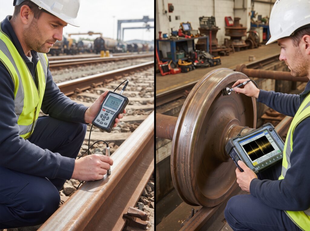
Ultrasonic thickness measurement is a nondestructive inspection method that determines the thickness of a material by measuring the travel time of an ultrasonic pulse.
A handheld gauge normally works with a transducer, couplant and display unit. The transducer sends the sound pulse into the material. When the pulse reaches a boundary, part of the sound returns to the probe. The instrument then uses the measured travel time and the material’s sound velocity to calculate thickness.
There is no single setup that handles every inspection equally well. The five approaches below address some of the most common situations encountered in industrial thickness work.
1. Contact Pulse-Echo Method
For ordinary thickness checks, contact pulse-echo is often the place to start.
The probe sits directly against the material and sends an ultrasonic pulse through it. The gauge looks for the echo from the opposite wall and uses that signal to determine thickness.
It works particularly well on accessible metal surfaces that are reasonably smooth. Plates, pipes, tanks and fabricated components can all fall into this category.
The attraction is obvious. The equipment can be portable, the reading takes little time, and there is normally no need to reach the opposite side of the component.
But a clean signal cannot always be expected. Loose scale, heavy corrosion, rough surfaces and poor probe contact can interfere with the measurement. If the signal becomes difficult to interpret, simply pressing the probe harder is not necessarily the answer. A different transducer or inspection approach may be more appropriate.
For routine ultrasonic thickness measurement, the contact pulse-echo method remains a practical choice when the material and surface conditions cooperate.
2. Dual-Element Method for Corroded Surfaces
Corrosion changes the problem.
A heavily corroded surface may contain pits and irregularities that make it difficult to identify a clean back-wall echo. A dual-element transducer approaches the problem differently. It contains separate transmitting and receiving elements, with their sound paths arranged to cross beneath the surface.
That arrangement can help focus the inspection area and locate the remaining wall beneath a corroded region. Dual-element probes are therefore useful when an inspection needs to find localised wall loss rather than simply obtain an average thickness.
Consider a storage tank with visible corrosion on the shell. A single measurement taken beside a corrosion pit might not tell the full story. Several readings around the damaged area can help establish where the wall becomes thinnest.
Probe selection still matters. A transducer designed for one thickness range should not automatically be used outside that range.
3. Through-Coating Measurement
Paint creates an awkward question during an inspection: should it be removed just to obtain a thickness reading?
Sometimes the answer is yes. Sometimes it does not need to be.
Specialised ultrasonic instruments can measure through suitable coatings, depending on the coating, substrate, probe and gauge. That can reduce unnecessary surface preparation and avoid damaging a protective finish.
This is particularly relevant in coating inspection, where the goal may be to determine dry-film thickness rather than remaining metal-wall thickness. Those are two different measurements and should not be confused.
The source material notes that ultrasonic coating gauges can measure coatings without destructive removal, while ASTM D6132 provides a standard method for nondestructive dry-film thickness measurement using an ultrasonic gauge.
For ultrasonic thickness measurement through a coated surface, the equipment needs to support that specific application. A standard thickness gauge should not automatically be assumed capable of measuring every coating system.
4. High-Temperature Thickness Measurement
Hot equipment introduces another limitation.
A conventional contact transducer may not tolerate direct contact with a high-temperature surface. Specialised probes and couplants can extend the usable temperature range, but the equipment must be rated for the conditions involved.
This matters in process plants where pipes, vessels or other equipment may remain warm during inspection. Temperature can affect sound velocity and probe characteristics, so the inspection procedure may need to account for it.
The source article notes that specialised dual-element and delay-line transducers can be used for higher-temperature applications, while ordinary contact transducers have much lower temperature limits. The exact limit depends on the equipment and manufacturer’s specifications.
So high-temperature ultrasonic thickness measurement is not simply a matter of taking an ordinary gauge into a hot area. The probe, couplant, calibration and operating limits all need to match the job.
5. Automated and Scanning-Based Measurement
A handful of spot readings may be enough for a small component. A large tank floor is a different matter.
When the inspection area is extensive, technicians can work across a grid or scan the probe along a defined path. Instead of collecting unrelated numbers, the inspection can build a picture of how thickness changes from one location to another.
Some advanced gauges can produce B-scan information as the probe moves. Data logging can also preserve readings for later review and comparison.
This makes scanning useful for corrosion mapping and larger inspection programmes. It does not remove the need for proper surface preparation or probe selection. It simply gives individual readings a wider context.
How to Choose the Right Method for the Inspection
The best ultrasonic thickness measurement method depends on the inspection rather than the number of features listed on a gauge’s specification sheet.
| Inspection situation | Suitable approach | Why it fits |
| Smooth, accessible metal | Contact pulse-echo | Quick and straightforward |
| Corroded or pitted surface | Dual-element | Helps identify local wall loss |
| Coated surface | Through-coating technique | Can avoid unnecessary coating removal |
| Elevated surface temperature | Specialised high-temperature setup | Designed for hotter conditions |
| Large inspection area | Scanning or mapping | Shows thickness variation |
Material type comes first. Expected thickness comes next. Surface condition, temperature, coating and component geometry can then narrow the choice.
Data requirements matter too. A basic gauge may be perfectly adequate for a few routine readings. A larger inspection programme may benefit from stored readings, A-scan displays or B-scan capabilities.
Buying the most advanced instrument available does not automatically produce better inspection results. The equipment has to fit the actual problem.
Where Is Ultrasonic Thickness Measurement Used?
The range of applications is broad because wall loss can occur in many types of equipment.
Ultrasonic thickness measurement is used for pipelines, storage tanks, pressure vessels, structural steel and manufacturing components. It can also support inspection work involving aircraft components and ship structures.
Pipelines provide an easy example. Internal corrosion may reduce the wall while leaving little evidence on the outside. Measurements taken at several locations can reveal whether the loss is concentrated in one area or spread along the pipe.
Storage tanks face similar issues. Corrosion can develop at particular locations, making repeat measurements useful.
Structural steel can also lose thickness through corrosion. Checking the remaining wall without cutting away sections of the structure can make inspection considerably more practical.
Manufacturing is another application. Thickness readings can help verify that components meet specified dimensions without destroying the parts being checked.
The real value appears over time. A reading taken today becomes much more useful when its location and previous readings are available for comparison.
What Affects the Accuracy of Ultrasonic Thickness Measurement?
Accuracy is not controlled by the gauge alone. The material, surface and inspection technique all have a say.
Several factors deserve attention:
- Surface roughness
- Corrosion and pitting
- Incorrect sound velocity
- Poor calibration
- Weak or inconsistent coupling
- Probe alignment
- Unsuitable probe selection
- Coatings and layered materials
- Elevated temperature
- Difficult component geometry
- Operator technique
A rough surface can scatter the ultrasonic signal. A deep corrosion pit can make the lowest remaining wall difficult to locate. A curved surface can also make consistent probe contact harder.
Then there is calibration. If the instrument is calibrated for the wrong material or an unsuitable reference, every subsequent reading can be affected.
That is why a technician should not accept an unusual result simply because the number appears stable on the display. A second reading, a nearby measurement or a different probe may tell a very different story.
How to Get More Reliable Thickness Readings
Good ultrasonic thickness measurement starts with preparation rather than the first press of the probe.
A practical inspection routine includes:
- Choose a transducer appropriate for the material and thickness range.
- Clean the measurement area and remove loose contamination.
- Select a couplant that suits the surface and temperature.
- Calibrate the gauge using a suitable known reference.
- Keep the probe stable during each measurement.
- Take additional readings around areas of concern.
- Record the exact measurement locations.
- Recheck results that appear inconsistent with nearby readings.
Multiple readings become especially important when corrosion is uneven. The lowest reliable reading may matter far more than an average calculated from several locations.
Records also have value beyond the current inspection. If the same points are checked during a later survey, the results can be compared with earlier data. That creates a much clearer picture of changing material conditions.
Advantages and Limitations of Ultrasonic Thickness Testing
The appeal of ultrasonic thickness measurement is easy to understand. It can provide thickness information without cutting the component, and many applications need access from only one side.
There are trade-offs, though.
| Advantages | Limitations |
| Nondestructive | Rough surfaces can affect readings |
| Often needs one-side access | Probe technique influences results |
| Portable equipment is available | Difficult materials may need specialised methods |
| Fast for spot checks | Coatings can complicate measurements |
| Useful for corrosion monitoring | Calibration remains important |
| Readings can be stored | Complex geometry can limit access |
What Is an Ultrasonic Thickness Gauge Used For?
An ultrasonic thickness gauge measures the thickness of a suitable material by analysing ultrasonic travel time. Inspectors use gauges for corrosion surveys, wall-thickness checks, manufacturing inspections and maintenance work.
Basic instruments can handle straightforward measurements. More advanced units may provide data logging, A-scan displays, B-scan functions, echo-to-echo measurement and specialised corrosion features.
For ultrasonic thickness measurement, the gauge is only one part of the setup. The transducer, calibration standard, couplant and inspection procedure all contribute to the final result.
How Thickness Readings Support Corrosion Monitoring
Repeated ultrasonic thickness measurement can turn separate inspection readings into a useful record of material condition.
Suppose a pipe wall measures 8.2 mm at a defined location during one inspection. A later inspection at the same point may show a different value. That comparison can help inspectors determine whether the wall is changing.
Corrosion surveys often focus on the minimum remaining wall rather than a broad average. Dual-element transducers can be useful for finding localised thinning and corrosion pits.
The measurements themselves do not decide whether equipment remains fit for service. Engineering assessment may need design information, operating conditions, material properties and applicable inspection requirements.
Final Thoughts
A thickness reading is small, but the information behind it can be important. Ultrasonic thickness measurement gives inspection teams a practical way to check remaining material without cutting into valuable equipment.
The five methods each have their place. Contact pulse-echo suits routine work, dual-element probes help with corrosion, through-coating techniques can preserve suitable protective finishes, specialised equipment handles hotter surfaces, and scanning provides a wider view across larger areas.
Used in the right conditions, ultrasonic thickness measurement can provide useful evidence for maintenance planning and asset integrity while leaving the inspected component intact.
Key Takeaways
- Ultrasonic thickness measurement checks material thickness without cutting or damaging valuable industrial components.
- Contact pulse-echo works well when the inspection surface remains reasonably smooth and accessible.
- Dual-element probes can help identify minimum wall thickness around corrosion and pitted surfaces.
- Through-coating techniques may reduce unnecessary coating removal during suitable inspection applications.
- High-temperature inspections require probes and couplants rated for the actual operating conditions.
- Scanning provides broader inspection coverage than isolated thickness readings on large components.
- Calibration errors can affect every subsequent reading, making pre-inspection checks especially important.
- Surface preparation helps the probe establish reliable contact with the material being inspected.
- Repeated readings provide useful evidence when inspectors monitor corrosion over longer periods.
- Critical thickness findings may require additional testing and engineering review before decisions.
Frequently Asked Questions
How accurate is an ultrasonic thickness tester?
Yes. An ultrasonic thickness tester can provide highly accurate readings when the gauge, probe, calibration and material conditions are appropriate. Actual accuracy varies between instruments and applications. Surface roughness, corrosion, temperature, sound velocity and probe positioning can all affect the result. Multiple readings and a suitable reference standard help establish confidence in ultrasonic thickness measurement results.
What is the ASTM standard for ultrasonic testing?
No. ASTM does not have one standard covering every type of ultrasonic inspection. ASTM E797/E797M addresses manual ultrasonic pulse-echo contact thickness measurement, while other standards cover different ultrasonic techniques and applications. The correct standard depends on the inspection objective, material and method. Inspectors should therefore identify the applicable requirement before starting ultrasonic thickness measurement work.
How do you calibrate an ultrasonic thickness gauge?
Yes. Calibration normally involves checking the gauge against a reference standard with a known thickness and suitable material properties. The operator may need to set the correct sound velocity and verify the instrument’s zero or probe characteristics, depending on the equipment. Manufacturer instructions should guide the procedure. Temperature and probe condition may also need consideration during ultrasonic thickness measurement.
What device can measure the thickness of a wall?
Yes. An ultrasonic thickness gauge can measure many walls when the material transmits sound effectively and the probe can obtain a reliable back-wall echo. This is useful for pipes, tanks and other structures where only one side is accessible. Surface condition, calibration, probe selection and repeated readings all influence the result, particularly when ultrasonic thickness measurement is used to investigate corrosion.
