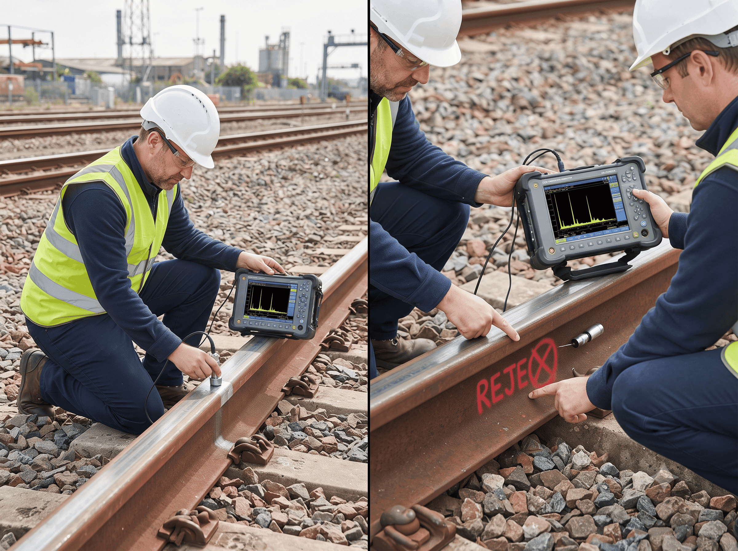
A weld can look flawed on an ultrasonic screen and still pass. That's the part most people outside the trade don't expect. Ultrasonic testing acceptance criteria exist precisely because a signal is not the same thing as a defect , the instrument reacts to geometry, grain structure, backing bars, and plenty of harmless reflectors long before it ever reacts to a crack. So the real work isn't spotting an indication. It's deciding, against a specific set of ultrasonic testing acceptance criteria, whether that indication is big enough, deep enough, or positioned badly enough to matter.
The complication shows up once the governing code enters the conversation. Take AWS D1.1's own worked example: a weld with an indication rating of +10 gets classified under Class A and rejected outright, but that rejection only holds because the connection was cyclically loaded. Run the same +10 rating through a statically loaded evaluation instead, and it clears the bar without incident. Nothing about the flaw changed. Only the code applied to it did. This article breaks down how reject levels get calculated in the first place, which standards define them, and why identical readings can send one job back for repair while waving another straight through.
What Ultrasonic Testing Acceptance Criteria Actually Determine
At the core, ultrasonic testing acceptance criteria define the dividing line between a harmless indication and a rejectable flaw. An indication is simply a response on the ultrasonic instrument; it could come from a crack, but it could just as easily come from weld geometry, backing bar reflection, or grain structure in the base metal. Acceptance criteria give the inspector a repeatable method for separating the two.
Four factors drive nearly every rejection decision built into ultrasonic testing acceptance criteria:
- Signal amplitude compared against a calibrated reference level
- Indication length, typically measured with the 6 dB drop technique
- Location of the flaw within the weld or component
- Orientation and depth relative to the surface
None of these factors work alone. A short indication with high amplitude might still pass, while a long indication with moderate amplitude might not. This is precisely why ultrasonic testing acceptance criteria in codes such as AWS D1.1 and ASME Section V combine amplitude and length into a single evaluation rather than judging either one in isolation.
How Reference Level Sets the Baseline for Rejection
Before any reject decision can be made, the equipment needs a baseline. That baseline is called the reference level, and it forms the backbone of nearly every set of ultrasonic testing acceptance criteria in use today.
What is the reference level in ultrasonic testing?
The reference level is the decibel reading required to bring the peak reflection from a known calibration reflector , commonly a side-drilled hole or an IIW reference block , up to a standard screen height, usually 50 percent of full screen height. Once that reference dB value is recorded, every subsequent indication found during scanning is measured against it. A flaw that reflects sound more strongly than the reference will read at a lower dB gain, and one that reflects weakly will require more gain to reach the same screen height.
Indication Rating and the Math Behind a Reject Call
Once the reference level is fixed, the inspector still needs a way to convert a raw dB reading into a decision. That conversion is called the indication rating, and it is where ultrasonic testing acceptance criteria stop being abstract and start becoming arithmetic.
The rating is calculated by subtracting two values from the instrument's dB reading at the flaw: the reference level itself, and an attenuation factor tied to how far sound has traveled through the material. Sound loses energy as it travels, so a flaw sitting deep in thick material naturally produces a weaker echo than an identical flaw closer to the surface. The attenuation factor compensates for that distance so flaws at different depths can be compared fairly.
Picture a 10-millimeter weld on a cyclically loaded structure. The reference level comes out to 65 dB, the beam path measures roughly three inches, and the scanning level ends up around 84 dB after adding a distance-based correction. When an indication appears and its peak is adjusted to the standard screen height, the instrument might read 79 dB. Subtracting the reference level and the attenuation factor from that reading produces the actual indication rating , and depending on which rating class the structure falls under, that single number decides whether the weld gets accepted or sent back for repair.
The formula gives an indication rating, but what actually counts as too high? The answer changes depending on which code is governing the job, so the next several sections break that down code by code.
Reject Levels Under AWS D1.1
AWS D1.1, the Structural Welding Code for steel, splits its ultrasonic testing acceptance criteria by loading condition. Cyclically loaded, non-tubular connections are judged under a stricter class rating than statically loaded structures, because fatigue cracking behaves very differently under repeated stress than under a static load.
Under this system, indications are sorted into classes based on the calculated rating value:
- Cyclically loaded, non-tubular connections fall under a stricter class, where a low-end rating is treated as automatically rejectable regardless of length or location
- Statically loaded connections tolerate a wider range of ratings before the same indication gets flagged, since the failure mechanism being guarded against is less sensitive to small imperfections
The gap between these two categories is not small. A weld that easily passes under a statically loaded rating table can fail outright once it is re-evaluated against the cyclic loading table, even though the raw ultrasonic reading never changed.
This loading-based split is one of the clearer illustrations of why ultrasonic testing acceptance criteria cannot be reduced to a single universal number. The same physical flaw, at the same dB rating, can pass under one loading condition and fail under another.
Reject Levels Under ASME Section V and Section VIII
Pressure vessel work follows a different logic entirely. ASME Section V, Article 4 governs how the ultrasonic examination itself is performed, while ASME Section VIII Division 1 supplies the acceptance standards applied to the results.
What are the NDT acceptance criteria for ASME Section 8?
Under Section VIII Division 1, any imperfection producing a response greater than 20 percent of the reference level triggers further investigation. The operator has to determine the shape, identity, and location of the imperfection before deciding whether it meets the acceptance standard. From there, two categories apply:
- Indications identified as cracks, lack of fusion, or incomplete penetration are unacceptable regardless of size
- Other indications become unacceptable once their length exceeds a threshold tied to weld thickness , roughly a quarter inch for thinner welds, one-third of the thickness for mid-range welds, and three-quarters of an inch for the thickest welds
That thickness-based sliding scale exists because a longer flaw matters more in a thin-walled vessel than in a thick one, proportionally speaking. Section VIII's version of ultrasonic testing acceptance criteria essentially scales the tolerance to the material itself rather than applying one fixed number across every wall thickness.
Reject Levels in Piping Codes: ASME B31.1, B31.3, and API 1104
Piping codes borrow heavily from the pressure vessel logic but adjust the details for the specific service. ASME B31.1, covering power piping, uses the same 20-percent investigation trigger as Section VIII, and applies nearly identical length-based thresholds tied to weld thickness. Cracks, lack of fusion, and incomplete penetration remain unacceptable outright, no matter how short they measure.
ASME B31.3, process piping, tightens the length threshold further for thinner-walled pipe and requires that pipe and tubing undergo full examination for longitudinal defects before any weld-specific evaluation begins. Any indication that reads stronger than the calibration notch used during setup is treated as a defect under this code.
API 1104, which governs pipeline welding, takes a noticeably different approach built around indication type rather than a single amplitude-and-length formula. Three broad categories cover most of the ultrasonic testing acceptance criteria applied under this code:
- Linear surface indications, evaluated against an aggregate length limit within any continuous section of weld
- Linear buried indications, which tolerate a slightly longer aggregate length since they sit away from the surface
- Volumetric indications, split further into cluster, individual, and root categories, each with its own maximum dimension
Cracks are treated as automatic rejects under API 1104 as well, consistent with nearly every other code discussed so far. What changes is how the remaining indication types get sized and grouped, reflecting the fact that pipeline welds are evaluated for service in a very different environment than a vessel nozzle or a structural connection.
Reject Levels for Valves: ASME B16.34
Valve inspection under ASME B16.34 applies ultrasonic testing acceptance criteria through a comparison method rather than a calculated rating. - Straight beam examination: any indication equal to or exceeding the response from a flat-bottomed reference hole of a set diameter is unacceptable
- Angle beam examination: the comparison shifts to a V-notch reference cut to a specific depth relative to the wall thickness
This comparison-based approach is simpler to apply in the field than the dB-subtraction method used elsewhere, though it still rests on the same underlying principle found throughout ultrasonic testing acceptance criteria: an unknown indication only means something once it is measured against a known, calibrated reflector.
Equipment, Calibration, and Why Reject Levels Only Mean What the Calibration Behind Them Means
None of the reject levels discussed so far mean anything if the equipment producing them is out of calibration. Most codes share a common baseline for equipment requirements, even though their acceptance tables differ.
- Pulse-echo type equipment, suitable for transducers operating between roughly 1 and 6 MHz
- A valid, current calibration certificate for the test instrument
- Gain control adjustable in discrete 1 or 2 dB steps across a range of at least 60 dB
- Recalibration required after an operator change, after roughly thirty minutes of continuous use, or whenever the electrical circuitry is disturbed by a transducer swap, cable change, or power interruption
A discontinuity judged acceptable under properly calibrated equipment represents a genuinely different claim than the same call made on a machine that has drifted out of calibration. This is exactly why codes spend so much text on equipment requirements rather than jumping straight to the acceptance tables , the tables behind ultrasonic testing acceptance criteria are only as trustworthy as the calibration performed before scanning begins.
Calibrated equipment only tells half the story. The other half depends entirely on who is reading the screen, which is where inspector qualification comes into the picture.
Wall Thickness and Its Effect on Reject Tolerances
Wall thickness shows up repeatedly across nearly every code discussed above, and for good reason. Thinner material tolerates far less indication length before a flaw is judged rejectable, while thicker material allows a proportionally longer flaw before the same rejection threshold applies. This scaling relationship is why a single flat number rarely appears in any acceptance table , thickness bands, fractions of thickness, and sliding scales show up instead.
Measurement tolerance matters here too. Reference blocks and calibration notches are manufactured to close dimensional tolerances specifically so that the thickness-based scaling built into ultrasonic testing acceptance criteria stays accurate. A calibration standard that is out of tolerance introduces error into every reject decision calculated against it, which loops back to why equipment and reference-block condition get so much attention throughout the codes covered in this article.
Key Takeaways
- Ultrasonic testing acceptance criteria always combine amplitude, length, location, and depth rather than judging any single factor alone.
- Reference level is the calibrated baseline every indication gets measured against, so an incorrect baseline throws off every reject decision downstream.
- Indication rating is calculated by subtracting the reference level and an attenuation factor from the raw dB reading at the flaw.
- AWS D1.1 applies stricter reject thresholds to cyclically loaded connections than to statically loaded structures, even for identical dB ratings.
- ASME Section VIII Division 1 triggers further investigation once an indication exceeds twenty percent of the established reference level reading.
- Cracks, lack of fusion, and incomplete penetration are treated as automatically unacceptable across nearly every major code discussed in this article.
- API 1104 organizes pipeline weld indications by type, such as linear surface, linear buried, and volumetric, rather than one universal formula.
- ASME B16.34 relies on direct comparison against a flat-bottomed hole or V-notch reference rather than a calculated numerical rating.
- Equipment calibration, gain accuracy, and recalibration intervals directly determine whether a reject decision will hold up under later scrutiny.
- Inspector qualification, typically at ASNT Level II or higher, ensures the person reading the screen can apply the correct acceptance table.
Final Thoughts
There's no single reject number hiding somewhere in these codes, waiting to be memorized. Ultrasonic testing acceptance criteria move with the standard, the load type, the wall thickness, sometimes even the specific component being examined , the +10 rating discussed earlier is proof enough of that. Good equipment calibration and a correctly set reference level get an inspector most of the way there. Applying the right acceptance table for the actual job closes the gap. Skip that last step, and even a technically accurate dB reading turns into a guess dressed up as a decision.
Frequently Asked Questions
What is the ASTM standard for ultrasonic testing?
There isn't just one. ASTM covers different materials and product forms under separate documents , E164 handles contact testing of weldments, E213 applies to metal pipe and tubing, and A435 is specific to steel plate. Picking the right one comes down to what's actually being inspected, not a single blanket standard that fits every case.
What are the acceptance criteria for AWS D1.1 NDT?
It depends heavily on load type. AWS D1.1 converts each indication into a numerical rating built from amplitude, reference level, and attenuation, then checks that number against class tables split by whether the connection is statically or cyclically loaded. Cyclic loading gets the stricter table , fatigue doesn't forgive small flaws the way static loading sometimes does.
What is the minimum thickness required for ultrasonic testing?
Roughly five to six millimeters, for conventional angle-beam work under most structural and pressure codes , though the exact figure shifts depending on probe type and the specific code being followed. Go thinner than that and near-surface reflections start blending into the actual flaw signal, which is usually the point where an alternative technique gets specified instead.
What are accuracy and acceptance criteria?
These get confused often, but they're not interchangeable. Accuracy is about the equipment , how closely its reading matches a flaw's real size and location, confirmed through calibration against known reference reflectors. Acceptance criteria come in after that: the predefined limits used to judge whether an accurately sized indication should pass or get rejected.