

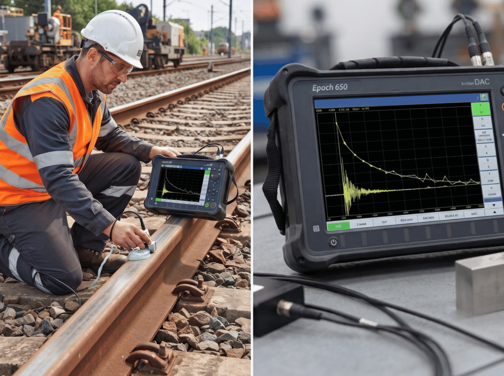
A DAC curve ultrasonic testing procedure is one of the most reliable calibration methods used to improve flaw detection accuracy during ultrasonic inspections. DAC curve ultrasonic testing allows inspectors to compensate for the natural reduction in echo amplitude as ultrasonic waves travel deeper into a material. Without DAC curve ultrasonic testing, identical discontinuities located at different depths could appear to have completely different sizes, leading to inaccurate inspection results.
Accurate flaw sizing is essential in industries where structural integrity directly affects safety, operational reliability, and regulatory compliance. Rail tracks carrying heavy freight, pressure vessels operating under extreme conditions, bridges supporting thousands of vehicles, and structural welds in industrial facilities all depend on precise ultrasonic evaluations. Even a small calibration error may cause an inspector to underestimate a critical defect or reject an otherwise acceptable component.
This guide explains how DAC works, why it remains one of the industry’s preferred calibration methods, how inspectors construct a DAC curve, common mistakes that reduce its accuracy, and where it is most frequently applied in rail and structural weld inspections.
Why DAC Curve Ultrasonic Testing Matters for Flaw Sizing
Reliable flaw sizing depends on comparing defects under equal evaluation conditions rather than relying on signal strength alone. This is precisely where DAC curve ultrasonic testing becomes essential.
Echo amplitude by itself cannot accurately represent flaw size because signal strength continuously changes with increasing sound path distance. Two discontinuities of identical dimensions may generate dramatically different amplitudes simply because one lies deeper within the material.
The concept of Equivalent Flaw Size (EFS) helps inspectors overcome this limitation. Instead of judging a reflector solely by its amplitude, the indication is compared against the DAC reference curve. If the echo exceeds the calibrated curve by a specified decibel value, the reflector may require further evaluation according to the applicable inspection code.
Incorrect sizing carries serious consequences.
An underestimated discontinuity could remain in service despite posing a structural risk. An overestimated indication may lead to unnecessary repairs, increased downtime, production delays, and significant financial losses.
The value of DAC therefore extends beyond calibration alone,it provides confidence that inspection decisions remain technically consistent regardless of reflector depth.
How DAC Curve Ultrasonic Testing Compensates for Signal Loss
One of the most important principles behind DAC curve ultrasonic testing is understanding why ultrasonic signals naturally decrease with distance. The reduction in echo height is not necessarily caused by a smaller flaw. Instead, it results from predictable physical behavior of ultrasonic waves.
Immediately after leaving the probe, the ultrasonic beam travels through the near field, where sound intensity fluctuates because of constructive and destructive wave interference. Beyond this region lies the far field, where the beam gradually spreads outward and loses energy over increasing distances.
Beam spread reduces the concentration of sound energy reaching deeper reflectors. At the same time, material attenuation absorbs part of the ultrasonic energy through internal friction, grain structure, and microscopic scattering. Together, these effects lower returned echo amplitudes even when reflector size remains unchanged.
A calibration curve compensates for these losses by establishing expected echo responses throughout the inspection range. Instead of increasing instrument gain for every reflector encountered, inspectors maintain fixed instrument settings while comparing indications against the DAC reference.
In many practical inspections, signal amplitude may decrease by approximately 6 dB whenever sound energy effectively halves because of propagation losses, although the exact reduction depends on material properties, probe frequency, beam angle, and inspection geometry.
Time Varied Gain (TVG) addresses the same physical problem using a different approach. Rather than displaying a reference curve, TVG electronically increases receiver gain over time to compensate automatically for attenuation. Both methods improve evaluation consistency, but DAC provides inspectors with a visible reference curve that many inspection procedures continue to require.
Understanding how attenuation affects ultrasonic responses naturally leads to another important question: what equipment is actually needed to build an accurate DAC curve?
How to Draw a DAC Curve in Ultrasonic Testing
Drawing a DAC curve ultrasonic testing calibration involves recording maximum echo responses from identical reference reflectors while maintaining constant instrument settings, then connecting those responses into a smooth reference curve used during flaw evaluation.
Select the Reference Block with the Greatest Metal Path Depth
The process begins by selecting an appropriate calibration block containing artificial reflectors located at different sound path distances. The block should closely match the acoustic characteristics of the component being inspected to minimize attenuation differences between calibration and production testing.
For angle beam inspections, side-drilled hole blocks are widely used because they provide consistent reflection characteristics over multiple sound paths. Normal beam inspections frequently rely on flat-bottom hole reference blocks instead.
Position the Probe for Maximum Reflection
After calibrating the instrument’s horizontal scale, the inspector scans across the first reference reflector while carefully adjusting probe position until the highest possible echo amplitude appears on the display.
Maximum echo response is critical because every plotted point on the DAC curve represents the strongest obtainable reflection from that specific artificial reflector.
Set the Gain So the First Echo Reads 80% Full Screen Height
Instrument gain is adjusted until the strongest reference reflector produces approximately 80% Full Screen Height (FSH).
This amplitude becomes the calibration reference for every remaining reflector used to construct the DAC curve. Once established, these gain settings should remain unchanged throughout the rest of the calibration procedure.
Freeze the Gain and Move to the Next Reference Reflector
After the first reflector has been calibrated to approximately 80% Full Screen Height (FSH), the instrument gain should remain unchanged. This is one of the most important principles of DAC curve ultrasonic testing because changing the gain during calibration would invalidate the relationship between the plotted points.
The probe is then moved to the second reflector located at a greater sound path distance. The inspector again searches for the maximum echo response by making small adjustments to probe position and scanning angle. Since the reflector is farther from the probe, the echo amplitude will naturally appear lower due to beam spread and material attenuation rather than a change in reflector size.
Maintaining identical instrument settings ensures that every recorded amplitude represents only the effect of increasing sound travel distance.
Mark Each Subsequent Peak Without Adjusting the Gain
The same procedure is repeated for every remaining reference reflector within the calibration block. Each maximum echo response is carefully marked on the instrument display or recorded using the flaw detector’s built-in DAC plotting function.
A common misconception is that every reflector should be adjusted to the same amplitude. In reality, only the reflector producing the highest reference response is initially adjusted to approximately 80% FSH. After that point, the gain remains locked while all subsequent reflector responses are recorded exactly as they appear.
This approach accurately captures the natural reduction in signal amplitude with increasing distance. Modern digital flaw detectors often automate point recording, but experienced inspectors still verify that each peak truly represents the maximum obtainable response before accepting the measurement.
Join the Marked Points into a Smooth Curve
Once every reflector has been measured, the recorded points are connected to form a smooth Distance Amplitude Correction curve.
Rather than drawing straight lines between individual measurements, inspectors create a continuous curve that represents the expected reduction in echo amplitude throughout the calibrated inspection range. During production inspections, every indication is compared against this reference. Signals exceeding the DAC curve by a specified decibel value may require additional evaluation according to the applicable acceptance criteria.
Many ultrasonic instruments also allow additional reference curves to be generated above or below the primary DAC line, like +6 dB, -6 dB, or -14 dB evaluation levels. These supplementary curves simplify acceptance decisions while maintaining consistent inspection procedures.
Verify the Calibration Before Inspection
Before beginning production inspections, the completed DAC curve should always be verified using the original reference reflectors.
Small variations in couplant thickness, probe pressure, temperature, or instrument drift can slightly alter echo amplitudes. Rechecking several reference points confirms that the calibration remains accurate and that the curve still represents actual inspection conditions.
For angle beam inspections, side-drilled hole (SDH) blocks are generally preferred, whereas flat-bottom hole (FBH) blocks remain common for many normal beam applications.
A completed curve provides a reliable reference,but only when it is interpreted correctly. Most inspection errors actually arise after calibration, making practical experience just as important as the procedure itself.
Common Mistakes When Building a DAC Curve Ultrasonic Testing Procedure
Even experienced inspectors occasionally introduce errors that reduce calibration accuracy. A carefully prepared DAC curve ultrasonic testing procedure minimizes these risks, but attention to detail remains essential throughout the inspection.
One common mistake is selecting a calibration block manufactured from a material with significantly different acoustic properties than the test component. Differences in grain structure or attenuation can shift the entire reference curve, reducing flaw-sizing accuracy.
Another frequent error occurs when probe pressure or couplant application changes between measurements. Even slight variations can affect echo amplitude enough to distort plotted reference points.
Some inspectors also fail to account for transfer losses caused by rough or curved inspection surfaces. Ignoring these corrections may produce overly optimistic calibration results that do not reflect actual inspection conditions.
Instrument drift presents another challenge during extended inspections. Periodically verifying the original reference reflector ensures that the calibration remains valid before additional components are evaluated.
Consistent technique, repeatable probe positioning, stable instrument settings, and disciplined verification practices help produce dependable inspection results.
DAC vs TVG: Two Ways to Compensate the Same Problem
DAC displays a visible reference curve created from known reflector responses. During inspection, indications are evaluated relative to this curve, allowing inspectors to determine whether a reflector exceeds established acceptance levels.
TVG, by contrast, applies electronic gain automatically as time progresses. Instead of displaying a reference curve, the instrument continuously amplifies deeper signals so reflectors of identical size appear at approximately the same screen height.
Many inspection codes continue to specify DAC because inspectors can visually compare indications against documented reference curves. TVG, however, offers faster evaluation in applications where electronic compensation is permitted.
The calibration method may vary between inspection procedures, but the industries depending on accurate ultrasonic evaluation remain remarkably consistent.
Where DAC Curve Ultrasonic Testing Is Used
The reliability of DAC curve ultrasonic testing makes it valuable across numerous industries where structural integrity cannot be compromised.
Railway inspections rely on DAC calibration to identify internal defects before they grow into service failures. Inspection programs operating under AREMA recommendations and Federal Railroad Administration (FRA) requirements frequently use calibrated ultrasonic methods to evaluate rail integrity over long track sections.
Structural steel fabrication also benefits significantly from DAC calibration. Weld inspections performed according to AWS D1.1, AWS D1.2, and AWS D1.6 require consistent flaw evaluation methods that support accurate acceptance decisions.
Pressure vessels, pipelines, power generation equipment, heavy forgings, castings, offshore structures, and industrial process equipment also depend on calibrated ultrasonic inspections performed in accordance with ASME requirements.
For organizations requiring dependable ultrasonic testing, partnering with experienced inspection specialists helps ensure calibration procedures align with applicable industry standards while supporting accurate flaw evaluation.
Final Thoughts
Accurate ultrasonic inspection depends on more than advanced equipment,it depends on reliable calibration. DAC curve ultrasonic testing provides a proven method for compensating for beam spread and material attenuation, allowing inspectors to compare reflectors consistently regardless of their depth within a component. By establishing a calibrated reference based on known reflector responses, DAC curve ultrasonic testing improves flaw sizing accuracy and supports informed inspection decisions.
Whether inspecting railway infrastructure, structural welds, pressure vessels, pipelines, or heavy industrial components, a properly constructed DAC curve reduces uncertainty and helps inspectors evaluate discontinuities with greater confidence. Following established procedures, maintaining stable calibration settings, selecting appropriate reference blocks, and verifying the curve throughout the inspection process all contribute to dependable results.
Key Takeaways
- A DAC curve compensates for ultrasonic signal loss, enabling consistent flaw evaluation regardless of reflector depth within the inspected material.
- Proper calibration using identical reference reflectors improves flaw sizing accuracy and reduces the likelihood of false acceptance or unnecessary rejection.
- Beam spread and material attenuation naturally reduce echo amplitude, making Distance Amplitude Correction essential for reliable ultrasonic inspections.
- Maintaining constant instrument gain after the initial calibration point ensures the DAC curve accurately represents signal reduction over increasing distances.
- Selecting calibration blocks manufactured from similar materials improves calibration accuracy and minimizes errors caused by differing acoustic properties.
- Regular verification of the DAC curve helps identify equipment drift, coupling inconsistencies, and other factors that could compromise inspection reliability.
- DAC curve ultrasonic testing remains widely accepted across industries following AWS, ASME, AREMA, ASTM, and other recognized inspection standards.
- Side-drilled hole and flat-bottom hole reference blocks provide consistent artificial reflectors for constructing accurate and repeatable DAC calibration curves.
Frequently Asked Questions
How to set up a DAC curve?
Yes. Setting up a DAC curve begins by selecting an appropriate calibration block with identical artificial reflectors positioned at different depths. The strongest reflector is adjusted to approximately 80% Full Screen Height (FSH), after which the instrument gain remains unchanged while maximum echo responses from the remaining reflectors are recorded. These points are then connected to form a smooth Distance Amplitude Correction curve.
What is calibration in ultrasonic testing?
Yes. Calibration in ultrasonic testing is the process of adjusting and verifying inspection equipment to produce accurate, repeatable, and reliable measurements before evaluating a test component. It involves setting parameters like range, sensitivity, velocity, and reference levels using certified calibration blocks, ensuring inspection results comply with applicable industry standards and project specifications.
What is FBH in ultrasonic testing?
Yes. FBH stands for Flat-Bottom Hole, an artificial reflector commonly machined into calibration blocks for normal beam ultrasonic testing. Because each hole has a known diameter and depth, FBHs provide consistent reference echoes for equipment calibration, DAC curve generation, sensitivity adjustment, and verification of flaw detection performance before production inspections begin.
What is amplitude in ultrasonication?
Yes. Amplitude in ultrasonication refers to the height or strength of the ultrasonic echo displayed on the flaw detector screen. It represents the amount of sound energy reflected back from a discontinuity or reference reflector. Since amplitude decreases with increasing sound path distance, calibration methods like DAC are used to compensate for this natural signal loss.
Meta Description:
Learn how DAC curve ultrasonic testing improves flaw sizing accuracy, how a DAC curve is created, and where it is applied in weld and rail inspections.
