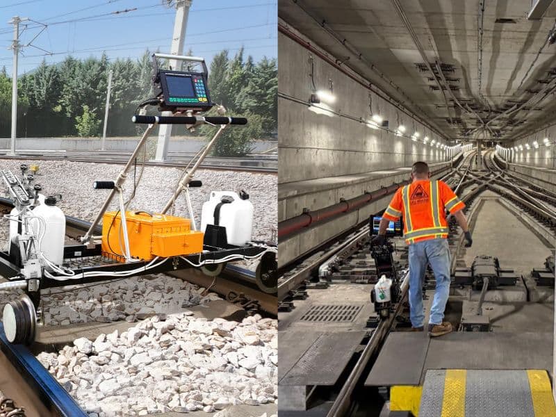
An ultrasonic flaw detector for rail inspection is a portable pulse-echo instrument that a qualified operator uses to hand-test rail: verifying test-car suspects within the four hours 49 CFR 213.113(b) allows, testing welds and joints, and covering track a test car couldn't search. It is typically run with 0°, 37–45° and 70° probes.
This guide covers the instrument itself. The test process as a whole is in how ultrasonic testing works for railways. What rail UT finds and misses is in ultrasonic rail testing capabilities, and screen interpretation is in how to read a flaw detector.
In this guide: where the instrument fits · channels, pulser and receiver · gates and displays · the probe set · calibration · DAC and TCG · worked example · welds, joints and frogs · records · choosing an instrument · test intervals · limits · FAQ.
Where does a hand-held flaw detector fit in rail testing?
A hand-held flaw detector is the verification and gap-filling tool of rail testing. Vehicles and carts find suspects; the portable instrument confirms, sizes and fills the gaps.
FRA's 2014 Improving Rail Integrity rule lists four detection processes, including a "portable test process" in which an operator is "pushing a test device over the rail at a walking pace" (79 FR 4234, p. 4237). Part 213 itself never uses the word "ultrasonic"; it requires "internal rail inspections", and UT is how the industry meets that. These rules shape how the hand instrument is used:
| Rule | What it requires | Where the hand instrument comes in |
|---|---|---|
| 49 CFR 213.113(b) | Verify an indication within 4 hours, or immediately for a suspected A, A2 or B defect | Hand test at the suspect to confirm type and size |
| 49 CFR 213.237(g) and (h) | Track without a valid search isn't inspected; re-search, 25 mph, or replace the rail | Hand testing can make the valid search over a short no-test stretch |
| 49 CFR 213.238 | Operator trained, authorized and qualified "for each type of equipment" | Qualification is tied to the specific instrument |
| 49 CFR 213.240 | Continuous testing: field verification within 84 h (36 h for suspected A, A2, B) | Field verification is still a hand test by a qualified person |
Key takeaway: the vehicle finds suspects; the hand-held ultrasonic flaw detector decides what they are.
What is inside a rail flaw detector: channels, pulser and receiver?
A rail flaw detector has the core of any pulse-echo instrument: a pulser that excites the probe, a receiver that amplifies the echoes, and a time base that turns echo time into sound path. What sets a rail unit apart is its probe set, gate setup and records.
Channels. A classic hand-held unit has one channel, and the operator changes probes as needed. Walking carts and some portable rail units are multi-channel, running a 0°, two or more angle probes and sometimes a side-looker at once, each with its own gain, range, gates and alarm. One single-rail cart's maker lists 0°, 45°, 58° and 70° probes for its standard version (UDS2-77; one vendor's figure, not a norm).
Pulser. Most digital instruments offer a spike pulser and a tunable square-wave pulser. Matching the square-wave width to the probe frequency usually improves low-frequency penetration, and damping trades resolution against signal strength.
Pulse repetition frequency (PRF). PRF must be low enough that each pulse's echoes die out before the next, or "wrap-around" ghost echoes appear. On a moving cart it must also be high enough to sample the rail closely. The same vendor's cart claims 1 mm between pulses at up to 5 km/h. At 5 km/h the cart moves 5,000,000 mm ÷ 3,600 s = 1,389 mm per second, so one pulse per millimeter needs at least 1,389 pulses per second on each channel.
Receiver. Gain is set in decibels: 6 dB doubles echo amplitude and 20 dB multiplies it by ten. Filters should bracket the probe frequency, commonly about 2–5 MHz on rail.
Key takeaway: channel count, PRF and filter range decide whether an instrument can keep up with your probe set and scanning speed.
How do gates and the display work on a rail flaw detector?
A gate is a window on the time base that watches one zone of the rail and alarms when a signal crosses its threshold. Gates are what keep a long scan consistent. A typical rail arrangement:
| Channel | Gate | Alarm logic | What it watches |
|---|---|---|---|
| 70° (forward and backward) | Head zone, below the running surface to head depth | Positive: echo rises above threshold | Transverse defects in the head |
| 0° | Flaw gate between running surface and base | Positive | Horizontal reflectors (split head, head-web separation) |
| 0° | Back-wall gate on the base echo | Negative: base echo drops below threshold | Loss of bottom from a reflector, a tilted crack or lost coupling |
| 37–45° | Web and bolt-hole zone | Positive, read against the bolt-hole echo | Bolt hole and web cracks |
Gate positions depend on the rail section and probe, so they belong in the written procedure, not a factory default.
A-scan. The A-scan plots echo amplitude against time. The time base gives sound path, from which depth and position along the rail are computed. Size comes from manual sizing; the screen never shows a defect's shape.
B-scan. A B-scan stacks A-scans along the scan line into a side view, which needs position data from an encoder, a cart odometer or a vehicle location system. A single-channel hand instrument without an encoder shows only the A-scan. Multi-channel carts and test cars often show a B-scan-style channel map, and the operator still checks the A-scan behind any suspect.
Key takeaway: in rail work, gates and the A-scan are the evidence; a B-scan tells you where to look.
Which probes does a rail flaw detector use?
The typical rail probe set is a 0° probe, angled probes of about 37–45°, and 70° probes looking forward and backward, with side-looking probes on some systems. No public source sets a standard North American channel list, so treat this as typical practice.
| Probe | Typical form | Main targets | Notes |
|---|---|---|---|
| 0° longitudinal | Hand contact, dual, sled or wheel | Horizontal split head, head-web separation, split web; loss of bottom | A vertical crack parallel to the beam shows only as loss of bottom |
| 37–45° shear | Hand, sled or wheel, forward and backward | Bolt hole cracks, web cracks | Read against the known bolt-hole echo |
| 70° shear | Hand, sled or wheel, forward and backward | Transverse fissures, detail fractures, engine burn fractures, weld defects in the head | Meets a transverse crack face about 20° off normal |
| Side-looker | Angled across the head | Vertical split heads, flaws off the centerline | Fitted on some systems |
Wheel probes put the transducers inside fluid-filled rubber wheels that roll on the head. A 1999 Mountain-Plains Consortium report describes three to six transducers per wheel, usually two wheels per rail, and "a total of as many as 12 transducers per rail" (MPC 99-106). It labels its angles as longitudinal, while rail 70° channels are normally shear wave, so don't reuse its angle math.
Sled probes slide on a film of water and are common on walking carts.
Hand probes on wedges are what the operator uses at the suspect. FRA's 2026 handheld study notes that flat probes couple poorly on heavy gauge-face wear (DOT/FRA/ORD-26/07), so contoured wedges help on worn rail.
The probe set is built around crack planes. The transverse fissure definition reads:
"Transverse fissure means a progressive crosswise fracture starting from a crystalline center or nucleus inside the head from which it spreads outward as a smooth, bright, or dark round or oval surface substantially at a right angle to the length of the rail." (49 CFR 213.113(d)(15))
A transverse fissure lies in a transverse plane, so the 70° beam finds it and the 0° beam doesn't. "Horizontal" describes a different defect, the horizontal split head of 213.113(d)(11), which is the 0° probe's target. See transverse fissure in rail and horizontal split head.
Key takeaway: specify the probe set by angle and direction, and match each angle to the crack plane it must find.
How is a rail flaw detector calibrated?
A rail flaw detector is typically set for zero, velocity, refracted angle and reference gain on a standard block, then proved on a rail reference standard or test rail with known reflectors. No FRA rule sets the method.
FRA's handheld study found that North American railroads have no standardized calibration procedure for handheld rail UT. Common practice is to set zero, velocity, angle and gain at 80% of full screen height on a known flaw, usually on an IIW Type 2 block. With a small exception, no two operators in the study produced statistically similar calibration results, and the report warns that "calibration errors can cause excessive false positives and false negatives" (ORD-26/07, July 2026).
A typical shift sequence, hedged as practice:
- Instrument check: battery, cable and probe, and that the instrument "is performing as intended" (213.238(b)(2)).
- Range and zero on the standard block, so known reflectors fall at their correct sound paths.
- Angle check of the 70° and 37–45° wedges, which wear and shift with temperature.
- Reference gain: peak the reference reflector to the procedure's height and record the gain.
- Rail check: scan a rail reference standard or test rail of the same section, with drilled holes or saw cuts, to prove each channel and gate. Test vehicles are typically checked on a test rail at the start, and often the end, of a shift; no public primary source describes a standard method.
- Recheck at the procedure's interval and after any probe or cable change.
Instrument performance is a separate periodic check. ASTM E317-21 is the active practice for evaluating pulse-echo instruments' linearity, resolution, sensitivity and gain accuracy; it sets no acceptance limits, so the procedure must. In Europe, EN ISO 22232-1:2020 covers instrument verification and replaced EN 12668-1.
Key takeaway: write the calibration steps and the reference rail into the procedure, because the regulation won't.
How do DAC and TCG work on a rail flaw detector?
DAC and TCG correct for the fact that the same reflector gives a smaller echo the deeper it lies. A distance amplitude correction (DAC) curve plots reference echo height at several depths; time-corrected gain (TCG) raises gain with time so those reflectors all reach one height, typically 80% FSH.
Evident's tutorial says a DAC curve "graphically compensates for material attenuation, nearfield effects, and beam spreading" (Evident: DAC and TVG). It gives a reporting reference, not a flaw size.
Rail depths are short and fixed. A 70° beam reaches the bottom of a 1-15/16 in. head at about 5.7 in. of sound path, and the 0° beam's main target is the base echo. So many rail procedures use a single reference reflector plus a fixed scanning gain instead of a full DAC. Where a procedure calls for DAC or TCG, build it from same-size reflectors at several depths in a rail reference standard, with the probe used in the test. Our DAC curve ultrasonic testing guide covers the method. Scan at a higher gain than the reference, evaluate at the reference, and record both.
Key takeaway: DAC, TCG or a single reference, the reference and scanning gains belong in the record.
Worked example: verifying a 70° suspect with a hand-held flaw detector
This example follows one head suspect from the cart call to the record, with every number recomputed. The rail section, readings and reported size are illustrative inputs; real verification follows the owner's procedure.
Inputs: 136RE rail, head depth 1-15/16 in. (1.9375 in.) from a supplier drawing (confirm against the section in use); 70° shear hand probe; steel shear velocity 0.1280 in./µs; a cart flags a 70° head suspect, and the track owner learns of it at 09:10; the instrument was proved on the reference rail at the start of the shift.
Step 1: the clock. Unless the owner has an indication of a defect needing action A, A2 or B, 213.113(b) allows four hours, until 13:10. If the cart signal suggested a large transverse defect (60% of head area or more, which calls for A2, or A at 100%), verification would have to be immediate.
Step 2: forward 70°. Looking toward increasing marks, the echo peaks at 2.40 in. of sound path with the probe index at 47.75 in. from a chalk reference.
| Quantity | Formula | Result |
|---|---|---|
| Depth below running surface | 2.40 × cos 70° = 2.40 × 0.3420 | 0.821 in. |
| Surface distance ahead of index | 2.40 × sin 70° = 2.40 × 0.9397 | 2.255 in. |
| Reflector position | 47.75 + 2.255 | 50.01 in. |
| Round-trip time (wedge excluded) | 2 × 2.40 ÷ 0.1280 | 37.5 µs |
Step 3: backward 70°. From the other side, the echo peaks at 2.45 in. with the index at 52.30 in.
| Quantity | Formula | Result |
|---|---|---|
| Depth | 2.45 × 0.3420 | 0.838 in. |
| Surface distance behind index | 2.45 × 0.9397 | 2.302 in. |
| Reflector position | 52.30 − 2.302 | 50.00 in. |
| Round-trip time | 2 × 2.45 ÷ 0.1280 | 38.3 µs |
Both directions put the reflector at the same point (50.01 vs 50.00 in.) and nearly the same depth (0.82 vs 0.84 in.). A reflector seen from both sides is strong evidence it isn't noise or coupling.
Step 4: depth check. Both depths sit inside the 1.9375 in. head, with no surface mark above. An internal origin fits a transverse fissure better than a detail fracture, which 213.113(d)(7) says starts "at or near the surface of the rail head". The final type is confirmed only when the rail is removed.
Step 5: vertical extent. With a 6 dB drop from the forward peak, the top edge falls at 1.95 in. of sound path and the bottom edge at 2.95 in.
| Edge | Formula | Depth |
|---|---|---|
| Top | 1.95 × 0.3420 | 0.667 in. |
| Bottom | 2.95 × 0.3420 | 1.009 in. |
| Vertical extent | 1.009 − 0.667 | 0.342 in. |
| Share of head depth | 0.342 ÷ 1.9375 | 17.7% |
Vertical extent isn't head area. The operator also scans across the head from gauge to field and converts both dimensions to percent of head area by the owner's sizing method. Suppose that gives 15% of head area.
Step 6: disposition and record. A 15% transverse fissure falls in the 5–<25% band, remedial action C in the 213.113(c) table. The operator marks the rail "on both sides of the web and base" (213.237(e)) and passes type, size and location to the owner's person designated under 213.7, who applies the action.
Check of the numbers. cos 70° = 0.34202 and sin 70° = 0.93969. 2.40 × 0.34202 = 0.8208; 2.45 × 0.34202 = 0.8379; 1.95 × 0.34202 = 0.6669; 2.95 × 0.34202 = 1.0090. 47.75 + 2.2553 = 50.0053; 52.30 − 2.3022 = 49.9978. 4.80 ÷ 0.1280 = 37.50 µs; 4.90 ÷ 0.1280 = 38.28 µs. All depths are less than the 1.9375 in. head depth.
Key takeaway: two directions, one position, a depth inside the head and a recorded size turn a cart call into a defect the owner can act on.
How is a flaw detector used on rail welds, joints and frogs?
Hand testing covers the places a test vehicle searches poorly: field welds, rail ends in joints, and rail around special trackwork.
Welds. Test cars scan "the head and web of the rail, and not the majority of the base", in the words of TTCI's thermite weld survey (TD-00-013, Kristan, 2000). Field welds therefore need hand UT of the base and web-base fillet. TTCI research found full base coverage "could not be achieved without using a 'full skip'", and suggested 45–70° for the base, 30–70° for the web and 45° for the fillets (TD-21-027, 2021). That is research guidance, so the weld procedure should state its own angles. In service, a defective weld under 213.113(d)(6) has discontinuities over 5% of head area individually or 10% in total. See aluminothermic weld inspection and flash-butt weld inspection.
Joints. Section 213.237(f) requires equipment "capable of detecting defects between joint bars". The 37–45° channels find bolt hole cracks through the head with the bars in place. Cracked bars are a 213.121 matter, not a rail flaw.
Frogs. Most mainline frogs are cast austenitic manganese steel, which FRA research calls "highly attenuative" and "coarse-grained"; in-service examination of these castings "currently use[s] only visual inspections" (FRA RR 22-25, 2022). A standard instrument can test the carbon-steel rail ends and welds at a frog, but the casting itself needs research-stage techniques. See switch and crossing inspection.
Key takeaway: welds and joints are where the hand instrument earns its keep; manganese castings remain outside routine UT.
What records does a rail flaw detector need to support?
49 CFR 213.241(c) lists six items every internal rail inspection record must contain, and most come from the instrument and the operator's notes.
| 213.241(c) item | Where it comes from |
|---|---|
| (1) Date of inspection | Instrument log or report header |
| (2) Track inspected, including beginning and end points | Test plan mileposts or vehicle location data |
| (3) Location and type of defects found under 213.113 | Verification result, measured from a fixed reference |
| (4) Size of defects, if not removed before the next train | Hand sizing, in percent of head area or inches |
| (5) Initial remedial action and its date | The owner's designated person |
| (6) Location of any track not tested under 213.237(g) | Operator's no-test log |
Records are kept "for at least two years after the inspection and for one year after initial remedial action is taken" (213.241(d)). Electronic records are allowed if, among other conditions, the inspector starts electronic storage within 72 hours of finishing (213.241(j)(5)).
Saving A-scans and gain values isn't required but lets a Level III audit a call later. Item (5) belongs to the owner, so contracts should say who completes which item.
Key takeaway: an instrument that saves screen, settings and location with every call makes the 213.241 record easy.
How do you choose an ultrasonic flaw detector for rail inspection?
Choose by the job: verification, weld testing or covering no-test stretches. Brand matters less than whether your operators are qualified on the model.
| Feature | What to check | Why it matters on rail |
|---|---|---|
| Channels | Single for verification; multi-channel for scanning length | Runs 0°, 37–45° and 70° at once |
| Pulser | Spike and square-wave, adjustable width and voltage | Low-frequency penetration for base and weld work |
| Receiver | Filters covering about 2–5 MHz; calibrated gain steps | Matches typical rail probes; supports E317 checks |
| PRF | Adjustable, high enough for scan speed | No ghost echoes, dense sampling |
| Gates | At least two, positive and negative (loss-of-signal) logic | Head flaw gate plus 0° back-wall monitoring |
| Display | A-scan readable in sunlight; B-scan where an encoder is used | Field visibility; side view for long scans |
| DAC/TCG | Built in, curves stored per probe | Where the procedure needs depth correction |
| Data | Saved screens with settings, time and location; export | 213.241 records and audit |
| Probes | Fits your 0°, 37–45°, 70°, sled or wheel probes | One instrument for track and welds |
| Field build | Shift-long battery, sealing, temperature range | Outdoor work in long windows |
Qualification is part of the purchase. Under 213.238(a), each provider must identify "the types of rail flaw detection equipment" each operator is trained and qualified on, and proficiency is shown "for each type of equipment" (213.238(c)). A new model can mean new training and authorization before it is used for a valid search.
Ignore claims you can't check. Vendor statements about automatic defect recognition or AI analysis aren't evidence of detection performance, and 213.238(b)(3) keeps interpretation the qualified operator's duty. Ask for a demonstration on your own reference rail and the instrument's E317 or ISO 22232-1 data. See also ultrasonic testing equipment and digital vs analog flaw detectors.
Key takeaway: the right instrument fits your probe set, your records and your operators' qualifications.
How often must rail be tested, and does a hand-held test count?
49 CFR 213.237(c) sets the interval: on Class 4 and 5 track, and on Class 3 track with scheduled passenger trains or a hazardous materials route, no more than 370 days or 30 million gross tons, whichever is shorter. Other Class 3 track is tested each calendar year (no more than 18 months apart) or every 30 MGT, whichever is longer, never more than 5 years apart. There is no interval for Class 1 and 2 track, and Class 6 and higher falls under 213.339.
A hand test can be a valid search where the operator meets the 213.238(b)(4) duty to:
"Determine that each valid search for an internal rail defect is continuous throughout the area inspected and has not been compromised due to environmental contamination, rail conditions, or equipment malfunction."
Hand testing covers short lengths; carts and vehicles cover lines. See how often must rail be tested.
Key takeaway: the interval comes from 213.237(c); the hand instrument fills gaps inside it.
What can't an ultrasonic flaw detector for rail inspection do?
It can't see through surface damage, can't size a defect by itself, and can't make up for a poor procedure or an unqualified operator.
- Head checks and shelling. Head checks are surface rolling contact fatigue cracks, typically 2–5 mm deep at the gauge corner (ARTC RC 2400, 2006). UT detects them poorly, and they and shells can hide deeper defects; FRA's RCF review says surface fatigue "prevents the successful transmission of ultrasonic waves to the base of the rail and back" (DOT/FRA/ORD-11/24, 2011). The only measured masking figure is for shells: in TTCI's 1998 benchmark, systems found about 62% of transverse defects under shells (7 defects) vs 77% with no surface anomaly (33) (TD-99-006, 1999). The answer is grinding or a no-test record, not more gain. See head checks in rail.
- Crack orientation. A crack parallel to the beam gives little or no echo.
- Coupling. Lost coupling is untested rail under 213.241(c)(6), not a false call.
- Manganese castings scatter sound; routine in-service examination is visual.
- Sizing. The screen shows amplitude and time; size comes from the operator's method and carries real error.
Key takeaway: when the surface blocks the beam, record the no-test and fix the surface.
How EMA Industries applies this
EMA Industries performs ultrasonic rail flaw testing and rail weld inspection for transit agencies, short lines and industrial track owners. We're based in Southern California and mobilize nationwide. Our operators hand-verify suspects, test field welds and rail at joints, and record each no-test location so the owner's 213.241 record is complete. To scope verification support, weld testing or a test procedure, see our ultrasonic rail testing services or contact us.
Related reading: How ultrasonic testing works for railways · Ultrasonic rail testing capabilities · How to read a flaw detector · Ultrasonic rail detection cart · False calls in rail UT · FRA defect codes explained
Frequently asked questions
What probe angles does a rail flaw detector use?
Typically 0° for horizontal defects and loss of bottom, about 37–45° for bolt holes and the web, and 70° forward and backward for transverse defects in the head. Some systems add side-lookers for vertical split heads. Exact angles vary by system.
How long does a track owner have to verify a flaw detector indication?
Four hours from when the owner learns of it under 49 CFR 213.113(b), or immediately for a suspected A, A2 or B defect. Owners using continuous testing under 213.240 have 84 hours, or 36 hours for suspected A, A2 and B defects.
How is a rail flaw detector calibrated?
Common practice sets zero, velocity, refracted angle and reference gain on a standard block such as an IIW Type 2, then proves each channel on a rail reference standard or test rail. No FRA rule or North American standard sets the method, so write it into the procedure.
Can ultrasonic testing detect head checks?
Poorly. Head checks are shallow surface fatigue cracks, and UT is aimed at internal defects. Heavy checking and shelling scatter or block the beam and can hide a deeper defect, so the response is grinding or a recorded no-test, then a valid search.
Does a hand-held flaw detector test count as a valid search?
It can, over the length the qualified operator covers continuously with equipment performing as intended (213.237(j)(4), 213.238(b)(4)). It is normally used for short lengths such as no-test stretches and new welds.
Sources
- 49 CFR 213.113, Defective rails, eCFR (text read on Cornell LII, October 2026)
- 49 CFR 213.237, Inspection of rail, eCFR
- 49 CFR 213.238, Qualified operator, eCFR
- 49 CFR 213.240, Continuous rail testing, eCFR
- 49 CFR 213.241, Inspection records, eCFR
- Track Safety Standards; Improving Rail Integrity, 79 FR 4234 (January 24, 2014), Federal Register
- DOT/FRA/ORD-26/07, MAPOD for handheld rail UT (ENSCO, July 2026), FRA via ROSA P
- DOT/FRA/ORD-11/24, Rolling Contact Fatigue: A Comprehensive Review (2011), FRA via ROSA P
- FRA RR 22-25, UT of special trackwork (2022), FRA via ROSA P
- TTCI TD-99-006, Benchmarking Results of North American Rail-Flaw Detection Technologies (Garcia and Reiff, 1999), MxV Rail
- TTCI TD-00-013, Thermite Weld Failure Survey (Kristan, 2000), MxV Rail
- TTCI TD-21-027, Thermite weld inspection after installation (Poudel, 2021), MxV Rail
- MPC 99-106 (Colorado State University, 1999), Mountain-Plains Consortium
- ASTM E317-21, Evaluating performance characteristics of pulse-echo UT instruments, ASTM store page
- EN ISO 22232-1:2020, Characterization and verification of UT equipment: instruments, SIS listing
- Evident: DAC and TVG tutorial, vendor tutorial
- ARTC RC 2400, Rail Defects Handbook (2006), Australian Rail Track Corporation