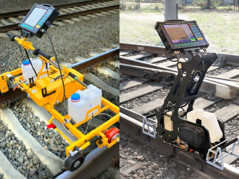
Long-range ultrasonic rail inspection sends low-frequency guided waves, roughly 20 to 80 kHz in published rail work, along the rail from one fixed transducer point. Reported defect-detection ranges run from about 40 ft (12 m) to about 1,200 ft (370 m) per direction, not miles, and the method does not give a 49 CFR 213.237 valid search.
Long-range ultrasonic testing (LRUT) and guided wave ultrasonic testing are two names for the same method. In rail it is mostly a research and monitoring tool. Its best-proven use is detecting complete rail breaks on a permanently instrumented line, not finding small cracks in the rail head.
This guide gives the ranges the literature actually reports, explains dispersion and mode selection, works through a time-of-flight calculation, and sets out where LRUT fits and where it doesn't.
What is long-range ultrasonic rail inspection?
Long-range ultrasonic rail inspection is guided wave ultrasonic testing applied to rail. A transducer array clamped or bonded to the rail excites elastic waves that fill the whole cross-section and travel along the rail as a waveguide, instead of a narrow beam that only probes the steel directly under the probe.
The names cause confusion. ASTM's pipe standard for the method, E2775, describes guided wave testing (GWT) as "previously known as long range ultrasonic testing (LRUT) or guided wave ultrasonic testing (GWUT)". So "guided wave" and "long-range UT" are the same technique, not competitors. EMA's article on guided wave vs long-range ultrasonic testing covers the naming in more detail.
The ASTM guided wave standards (E2775 for piezoelectric GWT and E2929 for magnetostrictive GWT) are written for pipe, and both call GWT a screening tool. We found no published standard for guided wave testing of rail in track. Rail work is governed by owner procedures and the research literature, not a code.
Guided waves are one of several ultrasonic wave types. EMA's overview of types of ultrasonic testing in NDT places them beside bulk longitudinal, shear and surface waves.
Key takeaway: LRUT is a long-reach screening and monitoring method, not a new kind of rail flaw detector car.
How does guided-wave rail testing work?
A guided-wave system sends a short tone burst into the rail and listens for echoes or for the signal's arrival at a distant receiver. The burst is usually a few cycles at a single center frequency in the tens of kilohertz, shaped by a window function to keep its bandwidth narrow.
There are two ways to use the wave, and they give very different ranges:
| Mode of operation | How it works | What it tells you | Typical published use |
|---|---|---|---|
| Pulse-echo | One transducer station sends and receives. Echoes come back from welds, rail ends and defects | Location and rough size of reflectors, from arrival time and amplitude | Defect monitoring trials; short-range inspection of a rail section |
| Pitch-catch (transmit-receive) | A transmitter sends; a receiver some distance away listens | Whether the rail between them is still continuous; loss of signal means a break | Permanently installed broken-rail detection |
The steps are the same in both cases:
- Attach the transducers. Field systems mount piezoelectric transducers under the head or on the web. One operational trial in South Africa used two transducers mounted under the head of the rail.
- Pick a mode and frequency. The excitation point and frequency are chosen so that one wave mode dominates, ideally one with low dispersion and low loss, concentrated in the part of the rail of interest.
- Send the burst both ways. The wave travels in both directions from the transducer unless an array is used to favor one direction.
- Record and process. Signals are averaged, filtered, and often dispersion-compensated before the analyst looks for reflectors.
- Convert time to distance. Each echo's arrival time is converted to a distance using the mode's group velocity, which is covered in the worked example below.
For how conventional ultrasonic rail testing works at megahertz frequencies, see EMA's guide to how ultrasonic testing works for railways.
Key takeaway: pulse-echo LRUT locates reflectors; pitch-catch LRUT only confirms the rail is unbroken.
How far can long-range ultrasonic rail inspection reach?
Published defect-detection ranges for guided waves in rail run from tens of meters to a few hundred meters per direction from one test point. Transmission-only signals, used to detect breaks, have been received over 1 to 3 km. No source we found supports "miles" of defect inspection from one point.
The range depends on the wave mode, the frequency, the rail section, how the rail is supported and fastened, curvature and temperature. These are the figures we could trace:
| Source | Setup | Range reported | What the range means |
|---|---|---|---|
| Gharaibeh et al., TWI / NDT 2009 | Test rail, 70 kHz, modeling and experiment | "up to 12m" from one access point | Pulse-echo inspection of a rail length |
| Loveday, Long and Ramatlo, Structural Health Monitoring, 2020 | Operational heavy-haul track, pulse-echo, two transducers under the head | Artificial defect at 370 m (about 1,214 ft) detected and located | Pulse-echo defect monitoring over a two-week trial |
| Xu et al., Scientific Reports, 2024 | 35 kHz, 75 kg/m heavy-haul rail | Effective signal at 1 km on a curved test line; detectable at 3 km on straight track | Through-transmission attenuation tests, not defect echoes |
| Sun and Mahomed, 2017 (review of the South African system) | Pitch-catch break detection, 30–35 kHz | Transmit and receive stations "spaced at 2.5 km intervals" | Detection of complete breaks between stations |
Three things stand out. First, the longest numbers are for signals that only have to arrive, not for echoes from defects. Second, defect echoes must make a round trip, so a pulse-echo system loses twice the attenuation of a one-way path. Third, curves raise attenuation: Xu et al. saw higher loss on curved segments than on straight track.
So, for planning, think of pulse-echo LRUT as reaching tens to a few hundred meters per direction on clean, straight, open track, and less on curves, around fittings, or where the rail is embedded. The original version of this article said "miles"; that claim is not supported.
Key takeaway: quote LRUT range as "tens to hundreds of meters per direction," and always say which mode of operation the figure comes from.
Why are dispersion and mode selection the main challenge?
Rail is a multi-mode waveguide, so at any frequency many guided wave modes can travel at once, each at its own speed. Gharaibeh and colleagues describe guided wave inspection of rail as challenging because of the rail's irregular cross-section, "the existence of a large number of wave modes in the kilohertz range and the presence of a substantial dispersion effect."
The numbers make the point. Xu et al. calculated 23 propagating modes at 35 kHz in a 75 kg/m rail using the semi-analytical finite element (SAFE) method. Each mode has a different vibration shape: some concentrate in the head, some in the web, some in the foot.
What is dispersion?
Dispersion means a wave's velocity changes with frequency. A tone burst always contains a band of frequencies, so in a dispersive mode the burst spreads out as it travels. A sharp 5-cycle pulse leaving the transducer can arrive hundreds of meters later as a long, smeared wave packet with a lower peak. That loses both sensitivity and the ability to separate two nearby reflectors.
Dispersion also creates two velocities you must not mix up:
| Velocity | What it describes | Use it for |
|---|---|---|
| Phase velocity | Speed of individual wave crests | Wavelength (λ = phase velocity ÷ frequency) and transducer design |
| Group velocity | Speed of the wave packet's energy | Converting echo arrival time to distance |
For mode 9 at 35 kHz in the Xu et al. rail, the SAFE phase velocity is 3,571 m/s and the group velocity is 2,669 m/s. The worked example below shows what happens if you use the wrong one.
How is a mode selected?
Mode selection means choosing a frequency, excitation point and transducer layout that put most of the energy into one useful mode. The aims are low dispersion near the chosen frequency, low attenuation, and sensitivity in the part of the rail you care about. Gharaibeh's group reported modes that were "relatively non-dispersive in the 20-80 kHz range". Xu et al. chose 35 kHz and an excitation point on the web to drive their selected mode.
Other effects complicate the signal further:
- Mode conversion. A weld, a defect or a change in support can convert part of the energy into other modes, which arrive at different times and look like extra echoes. Setshedi et al. (2019) saw three modes in pulse-echo reflections from thermite welds.
- Temperature. Temperature changes alter guided wave velocities and signals. The South African research group models temperature effects explicitly because they change the baseline the system compares against (Ramatlo et al., 2021).
- Changing track conditions. Loveday, Long and Ramatlo found that changes in environmental and operational conditions limit the smallest defect that can be detected.
Key takeaway: every LRUT result depends on knowing which mode you excited and what its group velocity is in that rail section.
Worked example: turning time of flight into distance
In pulse-echo LRUT, distance to a reflector = group velocity × echo arrival time ÷ 2, because the wave travels out and back.
This example uses the published values for mode 9 at 35 kHz in a 75 kg/m rail (Xu et al., 2024). Your rail section, mode and temperature will give different velocities, so measure yours on a known reflector before using these.
Step 1: locate an unknown echo. A reflection arrives 112.4 ms after the burst is sent.
d = 2,669 m/s × 0.1124 s ÷ 2 = 299.996 m ÷ 2 = 150.0 m (492 ft) from the transducer
Step 2: see the error from the wrong velocity.
| Velocity used | Value | Calculated distance for a 112.4 ms echo | Error |
|---|---|---|---|
| Group velocity, mode 9 (correct) | 2,669 m/s | 150.0 m (492 ft) | none |
| Phase velocity, mode 9 | 3,571 m/s | 200.7 m (658 ft) | +50.7 m (about +34%) |
| Bulk longitudinal velocity in steel | 5,900 m/s | 331.6 m (1,088 ft) | +181.6 m |
Using the phase velocity sends a dig crew about 166 ft (50.7 m) past the reflector. Using the megahertz-UT bulk velocity more than doubles the distance.
Step 3: check the velocity on a known reflector. Field signals contain echoes from thermite and flash-butt welds whose positions are on track charts. Suppose a weld recorded at 120.0 m gives an echo at 89.9 ms:
v_g = 2 × 120.0 m ÷ 0.0899 s = 240.0 ÷ 0.0899 = 2,669.6 m/s
That agrees with the published 2,669 m/s to within 0.03%, so the mode identification is consistent. A large mismatch would suggest the echo belongs to a different mode.
Step 4: estimate the resolution. A 5-cycle burst at 35 kHz lasts 5 ÷ 35,000 = 142.9 µs. At the group velocity its length in the rail is 2,669 × 0.0001429 = 0.38 m (15 in.). In pulse-echo, two reflectors closer than about half that, 0.19 m (7.5 in.), will merge, and dispersion makes the packet longer still with distance.
Step 5: compare the wavelength. The wavelength uses the phase velocity: λ = 3,571 ÷ 35,000 = 0.102 m (4.0 in.). A 2.25 MHz shear wave in steel has a wavelength of about 1.44 mm (0.057 in.), roughly 70 times shorter. That difference is why guided waves see cross-section changes well and small cracks poorly, which the next section covers.
What defects can guided waves find, and how small?
Guided waves respond mainly to changes in the rail's cross-section, such as a break, a large transverse crack or heavy web or base corrosion. They are poor at small, localized head defects, because a 4 in. (100 mm) wavelength interacts weakly with a crack a few millimeters across.
The reported minimum sizes vary widely and come mostly from modeling, laboratory tests or short rail sections:
| Source | Conditions | What was detected | How to read it |
|---|---|---|---|
| Gharaibeh et al., Proc. IMechE Part F, 2011 | Finite element modeling validated by experiment, modes chosen for head, web and foot | Transverse defects "as small as 2 mm and 5 mm in the head and foot" | Lab-scale result; the abstract does not state the range or which dimension the figure refers to |
| Loveday, Long and Ramatlo, 2020 | Operational track, 370 m away, artificial defect (a glued-on mass) | A growing reflector was detected and located | The authors expect a defect "significantly smaller than the critical size" would be detected; this is a projection, not a measured crack size |
| Xu et al., 2024 | Simulation and field tests at 35 kHz | Cracks in head, web and foot changed reflected and transmitted signals | Reported as "significant cracks"; no minimum size given |
| South African broken-rail system (Sun and Mahomed, 2017) | Pitch-catch over km-scale spacings | Complete breaks | Detecting cracks before a break was a stated goal that "would have additional value" if achieved |
Read those figures with care. A 2 mm result under laboratory conditions is not a field detection threshold over hundreds of meters of rail with welds, fasteners and temperature swings. No source we found gives a probability of detection for guided waves on in-service rail.
ASTM E2775, written for pipe, says severity estimates from GWT are qualitative only. The same caution applies to rail: LRUT can tell you something is there and roughly how large a reflector it is, but it does not size a transverse defect as a percentage of head area the way 49 CFR 213.113 requires for remedial action.
For the defects conventional rail testing targets, see EMA's guide to flaw detection in railways.
Key takeaway: treat LRUT as a cross-section-loss detector, and size anything it finds with conventional UT.
Does LRUT count as a 49 CFR 213.237 valid search?
No guided wave system is recognized as giving a 213.237 valid search, and LRUT should not be used in place of the required internal rail inspection. Section 213.237 requires internal rail inspections at set intervals and defines a valid search in paragraph (j)(4) as:
"a continuous inspection for internal rail defects where the equipment performs as intended and equipment responses are interpreted by a qualified operator."
Part 213 names no test method; the word "ultrasonic" does not appear in it. But the valid-search standard asks for a continuous inspection that finds internal defects of the kind 213.113 classifies by size, interpreted by a qualified operator under 49 CFR 213.238. Fixed-point LRUT doesn't reliably find or size small head defects, so it doesn't meet that standard in practice.
We know of no FRA approval of guided wave testing as a 213.237 search. An owner who wanted credit for it would need FRA's agreement, for example through a waiver under 213.17, the route FRA used to trial continuous testing from 2009. That is a statement about process, not a prediction that FRA would agree.
FRA has funded guided wave research for a narrower purpose. Its 2014 rail integrity rule describes research aimed at "minimizing the masking effect of transverse cracks by surface shelling". That is a supplement to the search, not a replacement for it. The rule text is on eCFR at 49 CFR 213.237, and EMA's 49 CFR 213.237 guide explains the intervals.
Key takeaway: LRUT can add information, but the 213.237 test still has to be run.
How does LRUT compare with conventional rail flaw testing?
Conventional ultrasonic rail testing is a moving scan, not a set of fixed test points. A test vehicle or walking cart rolls along the rail with wheel or sled probes, typically a 0° beam plus angled beams around 37–45° and 70°, so the "range per test point" framing used for LRUT doesn't apply. FRA's 2014 rule describes conventional rail UT frequencies as "normally" 2.25 to 5.0 MHz.
| Feature | Conventional rail flaw testing | Long-range ultrasonic rail inspection |
|---|---|---|
| How coverage is achieved | Continuous scan as the probes move along the rail | Waves travel from a fixed station |
| Frequency | About 2.25–5 MHz | About 20–80 kHz in published rail work |
| Wavelength in steel | About 1–3 mm | About 100 mm at 35 kHz |
| Best at | Transverse defects in the head (70°), horizontal and vertical splits, bolt-hole cracks, web defects | Complete breaks, large cross-section loss |
| Sizing | Relative sizing of defects (for example percent of head area) for 213.113 | Qualitative |
| Access needed | Running surface along the whole length | One clamp point per section |
| 213.237 valid search | Yes, when run as a valid search by a qualified operator | No |
| Maturity in North America | Standard practice | Research and niche monitoring |
The original article described pulse-echo testing as reaching "a few meters per test point". That was wrong. Pulse-echo is the principle behind conventional rail UT, and conventional rail UT covers whole subdivisions because the probes move.
Key takeaway: the two methods answer different questions, and only one of them meets 213.237.
Where does LRUT fit in a rail program?
LRUT fits where conventional probes can't reach the rail, or where you want continuous alarm coverage between scheduled tests. These are the uses with the strongest case:
| Application | Why LRUT helps | Caveat |
|---|---|---|
| Broken-rail monitoring on long, remote lines | A pitch-catch system checks rail continuity every few minutes without a train or crew; South Africa's iron ore export line of about 800 km (about 500 mi) uses one | Detects complete breaks; cracks before a break are not reliably found |
| Embedded and street-running rail | The head is reachable but the web and base are hidden by paving or embedment | Embedment can absorb guided wave energy; range may be short |
| Highway-rail grade crossings | Web and base corrosion under the crossing surface is invisible to visual and conventional rail inspection | No published rail-crossing field validation found |
| Screening of inaccessible rail | One clamp point can screen a length that is hard to reach, for example under a structure | Results guide where to excavate or test further; they don't clear the rail |
| Research on masked defects | FRA-funded work aimed at transverse cracks hidden by shelling | Research, not a field service |
The crossing case is real. In TSB report R19M0018 (New Brunswick, 2019), the rail web under a crossing had corroded from 14.28 mm to about 4 mm (0.562 to 0.16 in.). The TSB found the corrosion had not been identified by visual or ultrasonic inspections "because the web of the rail was hidden by the crossing surface". That is the kind of cross-section loss guided waves are suited to. EMA's guide to grade crossing rail inspection covers the conventional options.
Embedment cuts both ways, though. Research on pipes embedded in concrete (Leinov, Lowe and Cawley, 2016) found a transmission loss of 32–36 dB through just 0.4 m of fully embedded 8 in. pipe, and concluded that inspection "beyond a short distance will not be possible" in a fully embedded pipe. Partial debonding helped. That is a pipe result, but it warns against assuming long range in fully embedded rail.
Key takeaway: LRUT is a specialist add-on for hidden rail and break monitoring, sitting beside a conventional test program.
When should you not use LRUT?
Don't use LRUT where the job is to find, size and disposition internal rail defects under Part 213. Use conventional ultrasonic rail testing instead in these cases:
- Your annual or tonnage-based 213.237 test. LRUT doesn't give a valid search.
- Finding transverse defects in the rail head early. The 70° beam of a conventional test is built for this; guided waves need much larger defects.
- Sizing a defect for 213.113 remedial action. The remedial table works on defect type and size, which LRUT can't provide reliably.
- Short rail lengths with many welds, joints or switches. Each feature reflects and mode-converts energy, so echoes from defects get lost among echoes from the track.
- Bolted joint track. Every joint is a reflector or a break in the waveguide, which defeats the long range.
- Special trackwork and frogs. The geometry changes constantly, and cast manganese frogs are hard to test ultrasonically by any method.
- Fully embedded rail without a trial. Run a range trial on a known length first, because embedment can absorb most of the signal.
- Where no one on the team can identify modes. Without dispersion analysis and a known-reflector velocity check, distance readings can be badly wrong, as the worked example shows.
Key takeaway: if the decision is a 213.113 action, LRUT isn't the tool.
What are the limits of long-range ultrasonic rail inspection?
The main limits are poor sensitivity to small defects, signal complexity, and changing conditions along the track. In detail:
- Sensitivity. A wavelength of roughly 4 in. (100 mm) at 35 kHz makes small cracks weak reflectors. Laboratory figures of a few millimeters don't transfer to field ranges.
- Dispersion and mode conversion. Many modes, each at its own velocity, make signals hard to interpret without modeling.
- Coherent noise. Welds, rail ends, fasteners and supports all return echoes. A defect echo has to be told apart from that "baseline", usually by comparing against earlier signals.
- Environmental and operational changes. Temperature and traffic change the signals, which limits the smallest detectable defect in monitoring (Loveday, Long and Ramatlo, 2020).
- Range loss. Curves, fittings and embedment raise attenuation. Pulse-echo also loses twice the one-way attenuation.
- No sizing to the rule. Results are qualitative. There is no published rail POD and no rail-specific standard.
- Not a valid search. LRUT doesn't satisfy 49 CFR 213.237.
The method's strength is reach; its weakness is resolution. Surface waves sit at the other end of the scale: EMA's article on surface wave UT for rail covers the shallow-crack research and its own limits.
How EMA Industries applies this
EMA Industries provides ultrasonic rail flaw testing for transit agencies, short lines and industrial track owners, working from Southern California and mobilizing nationwide. Before any long-range or guided wave testing is specified, the first step is to name the question it must answer: break monitoring, hidden rail at crossings or embedded track, or the 213.237 test itself, which needs a conventional valid search. EMA's NDT Level III services can review a guided wave proposal and plan the conventional follow-up on anything it flags. See our ultrasonic examination services or contact EMA Industries to discuss your track.
Related reading
- How ultrasonic testing works for railways
- Flaw detection in railways
- Types of ultrasonic testing in NDT
- Surface wave UT for rail
- Broken rail: causes, defects and prevention
Frequently asked questions
How far can long-range ultrasonic testing inspect rail from one point?
Published pulse-echo results range from about 12 m (39 ft) on a test rail to 370 m (about 1,200 ft) on operational heavy-haul track, per direction. Transmission-only signals used for break detection have been received at 1 to 3 km. Curves, fittings and embedment shorten the range, so a trial on your own track is the only reliable figure.
Can guided waves find a transverse fissure in the rail head?
Only once it is large. Guided waves respond to cross-section loss, and at around 35 kHz their wavelength is about 4 in. (100 mm). Laboratory work has reported transverse defects as small as 2 mm in the head, but no field detection threshold or probability of detection has been published. Early transverse defects are found with the 70° beam of a conventional rail flaw test.
Can long-range UT replace annual rail flaw testing?
Not under current FRA rules. Section 213.237 requires a valid search, which is a continuous inspection interpreted by a qualified operator, and LRUT can't find or size the defects that search is meant to find. We know of no FRA approval of guided waves as a 213.237 method.
What frequencies does guided-wave rail testing use?
Published rail work uses roughly 20 to 80 kHz. South Africa's broken-rail system works at about 30–35 kHz, and one Chinese heavy-haul study chose 35 kHz. Conventional rail UT uses about 2.25 to 5 MHz, around 100 times higher, which is why the two methods find such different defects.
Is guided wave testing the same as long-range ultrasonic testing?
They are the same method under two names. ASTM E2775 calls it guided wave testing and notes it was previously known as long range ultrasonic testing (LRUT) or guided wave ultrasonic testing (GWUT).
Sources
- 49 CFR 213.237, Inspection of rail: eCFR (text read on Cornell LII)
- 49 CFR 213.238, Qualified operator: eCFR
- FRA, Track Safety Standards; Improving Rail Integrity, final rule, 79 FR 4234 (Jan 24, 2014): govinfo PDF
- Xu X, Wen Z, Ni Y, Shao B, Ma X, Pan Z. "Study on monitoring broken rails of heavy haul railway based on ultrasonic guided wave." Scientific Reports 14, 8667 (2024): doi.org/10.1038/s41598-024-59328-5
- Loveday PW, Long CS, Ramatlo DA. "Ultrasonic guided wave monitoring of an operational rail track." Structural Health Monitoring 19(6):1666–1684 (2020): doi.org/10.1177/1475921719893887
- Gharaibeh Y, Sanderson R, Mudge P, Ennaceur C, Balachandran W. "Investigation of the behaviour of selected ultrasonic guided wave modes to inspect rails for long-range testing and monitoring." Proc. IMechE Part F 225(3):311–324 (2011): doi.org/10.1243/09544097JRRT413
- Gharaibeh Y, Ennaceur C, Mudge P, Balachandran W. "Modelling guided waves in complex structures, Part 1: Rail." NDT 2009: TWI published paper
- Ramatlo DA, Loveday PW, Long CS, Wilke DN. "Modelling and simulation of ultrasonic inspections in welded rails subjected to practical environmental conditions." MATEC Web of Conferences 347:00034 (2021): doi.org/10.1051/matecconf/202134700034
- Sun B, Mahomed N. "Real-time ultrasonic rail health monitoring system for both heavy haul loads and high speed train: South Africa overview." Journal of Mechanics and MEMS 9(1):1–5 (2017): PDF
- Leinov E, Lowe MJS, Cawley P. "Investigation of guided wave propagation in pipes fully and partially embedded in concrete." JASA 140:4528–4539 (2016): doi.org/10.1121/1.4972118
- Setshedi IS, Loveday PW, Long CS, Wilke DN. "Estimation of rail properties using semi-analytical finite element models and guided wave ultrasound measurements." Ultrasonics 96:240–252 (2019): doi.org/10.1016/j.ultras.2018.12.015
- ASTM E2775-16(2023), Standard Practice for Guided Wave Testing of Above Ground Steel Pipework Using Piezoelectric Effect Transduction: ASTM store
- Transportation Safety Board of Canada, Rail Transportation Safety Investigation Report R19M0018 (2020): TSB report