
A rail can look flawless on the outside and still be failing on the inside. That’s the uncomfortable truth behind internal rail defects, and it’s especially true of the compound fissure in rail , a fracture that doesn’t just grow, it changes direction as it grows. Most internal defects fail along one predictable plane. This one starts as a horizontal split buried inside the rail head, then turns, curving toward the surface until it’s running nearly transverse to the rail. That shift is what makes it hard to catch early and dangerous once it’s advanced. This article walks through what the defect is, why it forms, how inspectors and testing equipment catch it, where it fits among other rail defects, and what federal rules require once one turns up.
What Is a Compound Fissure in Rail?
Strip away the terminology and it comes down to this: a compound fissure is an internal fracture that begins horizontal and ends up transverse. It starts as a separation running lengthwise inside the rail head, then bends , up, down, or sometimes both , until it’s cutting substantially across the rail rather than along it. Early on, before that bend happens, it can look almost identical to a horizontal split head on a test readout, which is exactly why misclassification is a real risk in the first stages of development.
Compare that to a transverse fissure, and the difference in origin is clear. A transverse fissure starts at a single point , a crystalline nucleus somewhere inside the head , and spreads outward from there, staying roughly perpendicular to the rail the whole way. A compound fissure has no such starting point. There’s no nucleus to find. It begins as a seam, a pocket of segregation, or some other manufacturing flaw running horizontally, and only turns transverse later, sometimes so gradually that both faces of the eventual break have to be examined just to trace where the horizontal portion left off and the transverse portion began. That two-stage geometry is exactly why railroads treat it as an oblique, higher-risk defect rather than lumping it in with simpler transverse breaks.
How Does a Compound Fissure Develop?
The origin of a compound fissure in rail traces back almost entirely to the manufacturing process. An internal longitudinal seam, a zone of chemical segregation, or a small inclusion trapped in the steel during casting or rolling creates a weak point inside the rail head. Under repeated loading, that weak point begins to separate horizontally, developing lengthwise inside the head before any visible sign appears on the surface. As the horizontal separation continues, stress concentrations at its edges eventually cause the crack to turn, progressing upward, downward, or in both directions until it becomes substantially transverse.
Growth in the early stages tends to be slow, and a rail carrying a compound fissure can often remain in service for a period of time before the defect becomes large enough to threaten structural integrity. Development is typically described as advancing to a size encompassing roughly 30 to 35 percent of the rail head’s cross-sectional area before the failure risk becomes acute, though the exact pace varies depending on traffic, axle loads, and rail condition.
Several operational and environmental stresses influence how quickly that growth occurs:
- Vertical wheel loading, including static, dynamic, and impact components, which increases bending stress in the rail head and accelerates crack propagation once the horizontal separation has formed.
- Lateral loading from wheel flanges, particularly on curves, which adds transverse stress components that can hasten the horizontal-to-transverse transition.
- Thermal stress in continuous welded rail, where temperature swings above or below the rail’s neutral temperature generate compressive or tensile longitudinal stresses that interact with the existing internal flaw.
- Residual stress from manufacturing or welding, left over from roller straightening, head hardening, or the thermal cycling associated with field or plant welds.
Together, these forces explain why this type of internal flaw rarely develops in isolation from broader track conditions. A rail section under heavy axle loads, subjected to significant thermal cycling, or carrying a poor rail profile is statistically more likely to see an existing internal seam accelerate into a full compound fissure than one operating under lighter, more stable conditions.
Why compound fissures are considered especially hazardous comes down to the unpredictability of an oblique failure plane. A straightforward transverse fracture, once its size is known, behaves in a relatively predictable way as it grows toward complete failure. A compound fissure, because it combines horizontal and transverse geometry, can fail along an oblique path that is harder to anticipate and, in some cases, harder to detect fully with a single testing angle. This defect is also strongly associated with rail manufactured before the widespread adoption of control cooling in the late 1930s, since the internal segregation and seams that seed compound fissures were far more common in pre-control-cooled steel. That said, modern high-alloy and high-chrome rail is not entirely immune, and inspectors are trained not to dismiss the possibility simply because a rail section is relatively new.
What Are the Types of Defects in Rails?
Understanding where a compound fissure in rail fits requires some context on the broader family of rail defects, since railroads and regulators generally organize these conditions by the plane in which they ultimately fail. Transverse-plane defects, including transverse fissures, compound fissures, detail fractures, engine burn fractures, and defective welds, are grouped together because they all tend to culminate in a fracture running roughly across the rail. Longitudinal defects, like horizontal split head and vertical split head, develop and grow lengthwise inside the rail, sometimes for several feet, before cracking out to the surface. Web defects, including split web and piped rail, involve separations through the vertical web section connecting the head and base. Base defects cover broken base and base fracture conditions, usually tied to a nick, impact, or poor bearing support. Finally, weld-related defects span flash butt, gas pressure, and thermite welds, generally originating from incomplete fusion, trapped slag, or shrinkage cracking during the weld process.
The table below summarizes how this defect compares to several other common rail defects in terms of origin, failure plane, and typical growth behavior.
| Defect Type | Typical Origin | Failure Plane | Growth Pattern |
| Compound Fissure | Internal seam, segregation, or inclusion | Horizontal, turning transverse | Slow initially, then oblique/accelerated |
| Transverse Fissure | Crystalline nucleus inside rail head | Transverse | Slow to 20–25%, then accelerated |
| Detail Fracture | Shelling, head checks, or flaking near surface | Transverse | Slow to 10–15%, then rapid or sudden |
| Horizontal Split Head | Internal seam or inclusion | Horizontal, lengthwise | Rapid once separation begins |
| Vertical Split Head | Internal segregation or seam | Vertical, lengthwise | Very rapid once opened |
This comparison makes clear why the defect occupies something of a middle ground among transverse-plane defects. It shares the internal manufacturing origin common to horizontal and vertical split heads, yet it ultimately produces a transverse-style failure similar to a transverse fissure or detail fracture. That dual character is precisely why it is classified separately and treated with particular caution in remedial action tables.
How to Detect Cracks in Railway Track?
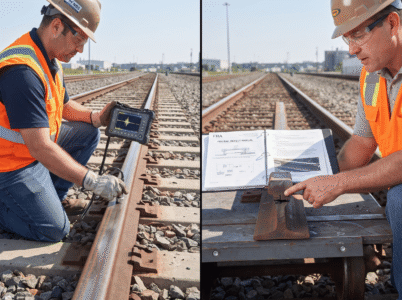
Because a compound fissure in rail develops entirely inside the rail head during its early and middle stages, it is essentially invisible to the naked eye until the defect either reaches the surface or the rail actually fractures. This reality is what makes nondestructive testing central to catching the condition before it results in service failure. Ultrasonic testing remains the dominant method used across the rail industry. Angled transducers, typically mounted in a wheel or sled assembly that rides along the top of the rail, send high-frequency sound waves into the steel. When those sound waves encounter an internal reflector, such as the horizontal or transverse components of a developing compound fissure, a portion of the signal reflects back to the transducer and is recorded as a potential defect for further interpretation. Induction testing serves as a complementary technology in some operations, passing direct current through the rail head to establish a magnetic field and then detecting distortions in that field caused by internal flaws.
Even with strong reliance on nondestructive testing, trained inspectors still watch for a handful of visible warning signs that can indicate an internal defect nearing the surface:
- A slight widening or dropping of the rail head along a specific length of track
- A dark or discolored streak appearing on the otherwise bright running surface
- A rust-colored or bleeding crack visible at the fillet area beneath the rail head
- A flat spot or dip developing on the running surface without an obvious external cause
These visual indicators typically appear only in the later stages of defect development, which is precisely why they function as a backup to testing technology rather than a substitute for it. By the time such a defect produces a clearly visible surface sign, the defect has often already progressed well beyond its earliest, safest stage of growth.
FRA Remedial Action Guidance for Compound Fissures
Once a compound fissure in rail is identified, either through nondestructive testing or visual inspection, federal regulation under 49 CFR 213.337 governs how a railroad must respond. The rule requires a qualified person, designated under the applicable track safety standards, to determine whether the rail can remain in service, and if so, which remedial action must be initiated based on the defect’s size relative to the rail head’s cross-sectional area.
The response scales directly with severity. Defects affecting the smallest measurable range of the cross-section may only require a speed restriction authorized by a qualified supervisor, generally capped around 30 miles per hour. As the affected percentage increases into a moderate range, the railroad must apply joint bars bolted through the outermost holes at the defect location within a defined window of time, often accompanied by an interim speed limit until the bars are installed. At the higher end of the severity range, where the compound fissure approaches or reaches full separation across the rail head’s cross-section, the remedial action becomes far more restrictive, requiring a qualified person to visually supervise every single train movement over the defective rail until it is replaced or repaired. Because compound fissures are known to develop along an oblique plane and to grow unpredictably once they pass a certain size, this graduated framework reflects a deliberate effort to match regulatory caution to the genuine unpredictability of the defect.
How to maintain the Compound Fissure in Rail?
Grinding and routine maintenance practices play a meaningful role in reducing the likelihood that a rail ever develops a compound fissure severe enough to trigger these remedial actions in the first place. Preventive rail grinding helps control rolling contact fatigue and maintain a favorable wheel-rail contact profile, reducing the localized stress concentrations that can accelerate an existing internal seam toward failure. Proper rail lubrication and friction management similarly reduce lateral loading in curves, one of the contributing stresses associated with faster fissure growth. For continuous welded rail specifically, maintaining rail neutral temperature within its intended range through proper anchoring and ballast maintenance helps limit the thermal stress component that can otherwise interact with an internal defect already present in the steel.
Final Thoughts
This defect represents one of the more complex internal conditions that railroads must manage, precisely because it combines two failure geometries into a single progressive fracture. Its manufacturing origin, its tendency to remain hidden until late in its development, and its capacity to fail along an unpredictable oblique plane all combine to make early detection genuinely difficult. Addressing that difficulty requires the coordinated use of manufacturing standards that reduce the internal seams and segregation responsible for the defect in the first place, nondestructive testing technology capable of catching the fissure before it reaches a dangerous size, trained inspectors who recognize the subtle visual cues that accompany advanced development, and a federal remedial framework that scales its response to the defect’s actual severity. As ultrasonic and induction testing technology continues to improve, and as railroads refine their grinding and maintenance practices, the industry’s ability to catch a compound fissure in rail well before it threatens service failure will only continue to strengthen.
Key Takeaways
- A compound fissure in rail begins as a horizontal separation inside the rail head before turning toward the transverse plane.
- Unlike a transverse fissure, this defect has no crystalline nucleus and instead originates from an internal seam or segregation.
- Growth typically stays slow until the defect reaches roughly 30 to 35 percent of the rail head’s cross-section.
- Wheel loading, lateral curve forces, thermal stress, and residual manufacturing stress all influence how fast a compound fissure in rail develops.
- The oblique failure plane makes this defect harder to predict than a straightforward transverse break once it advances.
- Rail manufactured before control cooling became standard in the 1930s is more prone to developing this type of internal flaw.
- Ultrasonic and induction testing remain the primary nondestructive methods used to catch a compound fissure in rail before it fails.
- Surface conditions such as shelling, head checking, and heavy rail wear can mask or distort test signals during inspection.
- Under 49 CFR 213.337, the required remedial action scales directly with how much of the rail head cross-section is affected.
- Preventive grinding, rail lubrication, and proper thermal stress management all reduce the long-term risk of a compound fissure in rail.
Frequently Asked Questions
Which defect is found during rail testing?
Yes, several internal defects turn up regularly during nondestructive rail testing, and the compound fissure in rail is one of the more serious ones inspectors watch for. Ultrasonic and induction equipment routinely flag transverse fissures, detail fractures, split heads, and defective welds as well, but a compound fissure stands out because of its oblique, two-stage growth pattern, which makes accurate early classification especially important.
What NDT is used for crack detection?
Yes, ultrasonic testing is the nondestructive testing method most widely used to detect cracks and internal flaws such as a compound fissure in rail. Angled transducers send sound waves into the rail and read the reflections bouncing back from internal defects. Induction testing serves as a secondary method in some operations, detecting distortions in a magnetic field passed through the rail head.
What is the rail break detection system?
Yes, rail break detection typically relies on a combination of nondestructive testing vehicles and, on many systems, electrical track circuits that sense a physical break in continuity. Ultrasonic detector cars, portable handheld units, and continuous monitoring systems all work together to catch conditions like a compound fissure in rail before they progress to a full service failure.
What is FRA and AAR inspection?
Yes, FRA and AAR inspections both involve evaluating track and rail condition against established safety standards, though they serve different roles. FRA inspectors enforce federal Track Safety Standards under 49 CFR Part 213, while AAR-related guidance reflects industry best practices among member railroads. Both frameworks address how a compound fissure in rail should be identified, reported, and remediated.