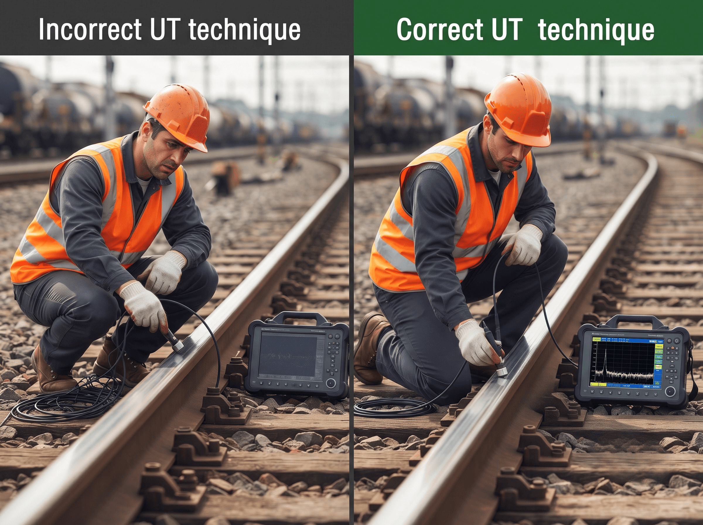
Ultrasonic rail inspection plays an important role in identifying internal defects that may not be visible during a routine visual examination. Ultrasonic testing mistakes can reduce inspection reliability even when modern flaw detection equipment is in use. In rail applications, ultrasonic testing mistakes can result from surface conditions, calibration, probe selection, coupling, signal interpretation, and other factors that influence how ultrasonic energy travels through the rail.
Rail flaw detection is not simply a matter of placing a probe on the rail and looking for an echo. The process depends on suitable equipment, correct settings, consistent scanning conditions, and accurate interpretation of returned signals. An error at one stage can affect the quality of results at several stages that follow.
What Can Affect Rail Flaw Detection?
| Inspection factor | Potential effect |
| Rail surface condition | Can affect coupling and signal quality |
| Probe configuration | Influences beam path and inspection coverage |
| Calibration | Affects measurement and sensitivity accuracy |
| Acoustic coupling | Can weaken or destabilize the received signal |
| Rail geometry | Can alter the intended ultrasonic beam path |
| Signal interpretation | Can result in false or missed indications |
| Data verification | Determines whether questionable indications receive follow-up |
These factors show why ultrasonic testing mistakes often begin with routine steps that appear relatively minor. Once these factors are understood, the first question becomes clear: which ordinary inspection practices create the greatest risk?
Incorrect Gate or Detection Threshold Settings
Gates define the portion of an ultrasonic response that the instrument evaluates for a particular purpose. Incorrect gate placement can exclude relevant signals, while inappropriate threshold levels can make the system either less sensitive or more susceptible to unwanted indications.
Gate settings should match the intended inspection zone and expected signal path. The settings also require verification against the applicable reference standard and inspection procedure.
Incorrect gate settings can create ultrasonic testing mistakes that remain hidden because the instrument may appear to operate normally. A signal outside the selected gate may never trigger the expected indication even though ultrasonic energy reached the relevant region.
Careful verification of gates and thresholds helps ensure that the instrument evaluates the signals that matter rather than simply displaying a technically valid waveform.
Failing to Recognize Near-Surface Limitations
Defects located close to the transducer can present particular challenges because ultrasonic beam behavior changes in the region immediately beyond the probe. Understanding this behavior helps explain why some near-surface indications require careful interpretation.
What Is Near Zone and Far Zone in Ultrasound?
The near zone, also known as the Fresnel zone, is the region close to the transducer where the ultrasonic field can show complex variations in sound pressure. The far zone, or Fraunhofer zone, begins beyond this region, where the beam generally follows a more predictable diverging pattern.
The distinction matters because defect responses can vary depending on their position within the ultrasonic field. Near-surface defects can become difficult to evaluate when the equipment, probe, rail geometry, and inspection frequency create conditions that make separation between the initial pulse and a flaw response less clear.
This is another area where ultrasonic testing mistakes can result from assuming that every part of the rail produces the same ultrasonic response. Inspection personnel need to understand the limitations of the selected equipment and procedure when evaluating indications close to the inspection surface.
The near zone and far zone are technical foundations rather than isolated inspection problems. Their practical importance becomes clearer when the entire inspection method is considered as one system, from equipment setup and calibration to signal interpretation and verification.
Why Multiple Inspection Technologies Can Help
A combined approach can provide:
- Ultrasonic information about internal discontinuities
- Visual information about surface conditions
- Additional coverage in difficult inspection areas
- More context for evaluating questionable indications
- Better opportunities for verification before a final assessment
The key is selecting technology according to the inspection objective rather than adding equipment simply because it is available.
Poor Data Recording, Verification and Follow-Up
Inspection does not end when the scanning equipment completes its route. Recorded data needs proper review, and questionable indications require appropriate verification.
Poor documentation represents one of the less visible ultrasonic testing mistakes. Without reliable records, it becomes difficult to establish where an indication occurred, which equipment and settings were used, whether the response was verified, and what action followed.
Modern rail inspection systems can capture substantial amounts of inspection information. Continuous testing workflows can identify indications during a scan, transfer data for analysis, and allow qualified personnel to review and verify significant responses.
That process creates a useful distinction between indication detection and defect confirmation. An automated system can identify a response, but the response still requires evaluation within the applicable inspection procedure.
A strong data-management process should maintain:
- Inspection location
- Equipment and probe information
- Relevant calibration details
- Recorded ultrasonic responses where applicable
- Indication assessment
- Verification results
- Final inspection documentation
Good records also support historical comparisons. A recurring indication or changing response can provide useful information when inspectors evaluate the condition of a rail over time.
The scan may be complete, but the inspection process still has another important stage: preventing the same errors from recurring.
How to Avoid Ultrasonic Testing Mistakes in Rail Inspection
Preventing ultrasonic testing mistakes requires a consistent process rather than reliance on operator memory. A practical inspection workflow can divide the controls into three stages.
Before Inspection
The inspection team should:
- Review the applicable inspection procedure and requirements.
- Examine the rail condition and identify significant surface irregularities.
- Check the condition of the ultrasonic equipment and probes.
- Confirm the appropriate probe configuration.
- Complete calibration using the required reference standard.
- Verify instrument settings, gates, sensitivity, and relevant parameters.
- Confirm that the coupling system and data-recording equipment operate correctly.
These checks establish a controlled starting point. They also reduce the likelihood that ultrasonic testing mistakes will originate from an incorrect setup.
During Inspection
During scanning, attention should remain on both the equipment response and the physical rail condition.
Coupling should remain consistent, signal quality should be monitored, and unexpected changes should receive appropriate attention. Changes in rail profile, surface condition, or inspection response can indicate a need for additional evaluation.
The inspection procedure should determine how suspicious indications are handled. An operator should not dismiss an unusual response simply because it appears inconvenient or resembles a previous false indication.
After Inspection
The final stage should include:
- Review of recorded indications
- Verification of questionable responses
- Appropriate comparison with historical inspection data
- Completion of inspection records
- Reporting and escalation according to the applicable procedure
This three-stage approach turns ultrasonic testing mistakes into identifiable process controls rather than isolated operator errors.
What Are the Different Types of UT Inspection?
Ultrasonic inspection covers several techniques, and each technique serves different purposes. Conventional pulse-echo testing uses a transducer to introduce ultrasonic energy and analyze reflected signals. Phased array ultrasonic testing uses multiple elements to control and steer ultrasonic beams, while guided-wave testing uses waves that propagate along a structure over a longer distance.
For rail inspection, the appropriate method depends on factors such as defect type, inspection range, rail geometry, access, required coverage, and the purpose of the examination.
Understanding these differences helps reduce ultrasonic testing mistakes because equipment selection becomes connected to the actual inspection requirement. A long-range screening technique, for example, should not automatically be treated as a substitute for a localized inspection designed to characterize a specific indication.
Guided-Wave and PAUT Applications in Rail Testing
Guided-wave testing offers a different approach by allowing ultrasonic energy to travel along the rail. This can make the technique useful for selected long-range inspection applications and areas where conventional access presents difficulties.
PAUT takes a different approach. Multiple elements can generate different beam angles and focal laws, allowing the inspection system to examine a broader range of paths. This capability can help address some challenges associated with changing rail profiles and complex defect orientations.
Neither technique removes all ultrasonic testing mistakes. Both require appropriate system configuration, calibration, data interpretation, and qualified personnel. Their value comes from applying their particular capabilities to inspection problems that conventional approaches may not address efficiently.
Why Operator Training and Data Review Matter
Equipment capability cannot replace inspection knowledge. Operators need to understand calibration, probe selection, coupling, rail geometry, signal behavior, and defect characteristics.
Training also helps inspectors recognize when a signal deserves further attention. Many ultrasonic testing mistakes involve interpretation rather than equipment failure. A technically strong operator considers the signal together with its location, beam path, rail condition, scanning behavior, and inspection setup.
Regular review of inspection data can reinforce this process. Historical records, verified indications, and inspection trends can help identify recurring problems and improve future inspection decisions.
Final Thoughts
Reliable ultrasonic rail inspection depends on more than advanced equipment. Proper surface preparation, probe selection, calibration, coupling, signal interpretation, rail geometry, data verification, and operator expertise all contribute to dependable flaw detection. Ultrasonic testing mistakes can arise at any stage when inspection procedures receive insufficient attention or when indications are not properly evaluated.
A structured approach before, during, and after inspection helps control these risks while improving consistency and traceability. Advanced methods such as PAUT and guided-wave testing can provide valuable complementary capabilities when applied appropriately. Ultimately, reducing ultrasonic testing mistakes requires disciplined procedures, suitable technology, trained personnel, and thorough verification of inspection results.
Key Takeaways
- Defining ultrasonic testing mistakes helps improve the consistency and reliability of rail flaw detection.
- Poor rail surface conditions can affect ultrasonic signal quality and inspection reliability.
- Correct probe selection helps provide suitable coverage of critical rail inspection areas.
- Proper calibration reduces ultrasonic testing mistakes related to sensitivity, measurements, and instrument settings.
- Consistent acoustic coupling helps maintain stable ultrasonic transmission throughout rail inspection.
- Rail-head wear and geometry can influence ultrasonic beam paths and inspection coverage.
- Careful signal interpretation helps reduce ultrasonic testing mistakes involving false or missed indications.
- Correct gate and threshold settings support more reliable automated flaw detection.
- PAUT and guided-wave methods can complement conventional ultrasonic inspection for suitable applications.
- Training, data verification, and disciplined procedures remain essential for reliable rail flaw detection.
Frequently Asked Questions
What are common defects found by ultrasonics?
Yes. Ultrasonic testing can detect internal discontinuities such as cracks, fissures, splits, inclusions, and other material flaws. In rail inspection, understanding common ultrasonic testing mistakes is equally important because surface conditions, probe selection, coupling, defect orientation, and calibration can influence whether an internal defect produces a detectable ultrasonic response.
What is the most common technique used in ultrasonic testing for flaw detection?
Yes. Pulse-echo testing is one of the most commonly used ultrasonic techniques for flaw detection. It sends an ultrasonic pulse into the material and analyzes echoes returned from internal boundaries or discontinuities. Avoiding ultrasonic testing mistakes during calibration, probe setup, coupling, and signal interpretation helps inspectors obtain more reliable results from pulse-echo inspections.
Which defect is found during rail testing?
Yes. Ultrasonic rail testing can identify internal defects such as transverse defects, transverse fissures, compound fissures, split heads, web defects, and other discontinuities. The ability to detect these defects depends on their size, orientation, and location, as well as rail geometry and inspection conditions. Minimizing ultrasonic testing mistakes helps improve the reliability of rail flaw detection.
What are two disadvantages of ultrasonic testing?
Yes. Two important disadvantages include the need for skilled interpretation and sensitivity to inspection conditions. Surface irregularities, poor coupling, complex rail geometry, unfavorable defect orientation, and near-surface conditions can affect ultrasonic responses. These limitations make controlling ultrasonic testing mistakes important. Proper calibration, suitable equipment, controlled scanning, and qualified personnel can help reduce these inspection challenges.
What are the types of defects?
Yes. Rail defects can occur in different parts of the rail and take different forms. Examples include transverse defects, transverse fissures, compound fissures, detail fractures, horizontal split heads, vertical split heads, split webs, and head-web separations. Ultrasonic testing can identify several internal defects, although ultrasonic testing mistakes can affect detection when defect size, orientation, location, or inspection conditions are unfavorable.